9. Embedded programming
making the board
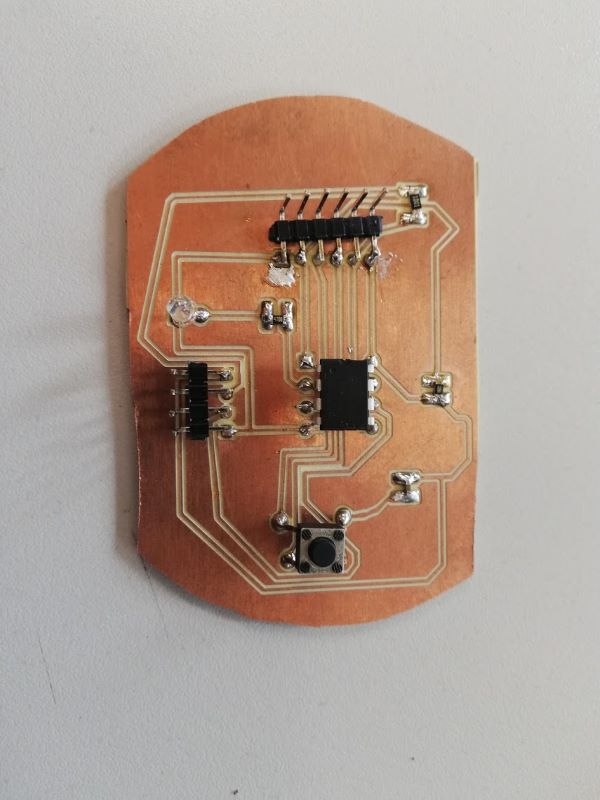
For this weeks assigment i also made a board. I used kicad for this. Solderder all the components on it.
datasheet ATtiny 45
i have used this datasheet for extra information about the attniny A data sheet is a very, very, very long manual of the microprocessor, it is very hard for on to read it entirely, and so I just searched whatever I needed in it. here you can check the data sheet I used with the ATtiny45 I used previously.
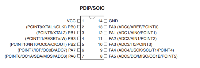
The first thing I found in the datasheet was the pinout for the microchip. This proved to be very usefull infomation. I needed this information for the work later on
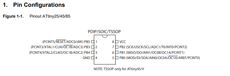
Underneed the visual pinout was a expanation af every pin.
- VCC : supply voltage
- GND : Ground
- Port B : Port B is a 6-bit bi-directional I/O port with internal pull-up resistors (selected for each bit). The Port B output buffers have symmetrical drive characteristics with both high sink and source capability. As inputs, Port B pins that are externally pulled low will source current if the pull-up resistors are activated. The Port B pins are tri-stated when a reset condition becomes active, even if the clock is not running.
- RESET : Reset input. A low level on this pin for longer than the minimum pulse length will generate a reset, even if the clock is not running and provided the reset pin has not been disabled.
testing the button and the LED
The first thing i did was testing the LED and the push button. I wrote a little code in arduino to test this.
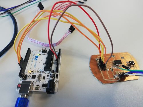
- GND —> GND
- PB2 —> SCK —> D13
- PB1 —> MISO —> D12
- PB0 —> MOSI —> D11
- Reset —> D10
- VCC —> 5V
int pshbutton = 4;
int LED1 = 3;

void setup() {
  // put your setup code here, to run once:
  pinMode(pshbutton, INPUT_PULLUP);
  pinMode(LED1, OUTPUT);
}

void loop() {
  // put your main code here, to run repeatedly:
if (!digitalRead(pshbutton))
{
  digitalWrite(LED1,HIGH);
}
else
  digitalWrite(LED1,LOW);

}
In human words this code does the following, if the button is pressed the light goes on. If the button is not pressed the light will be off. This did work so the button was soldered correct.
blokkencode
After the test i tried to make a little program, i used blokkencode to make the code. This is a tool we use at ingegno makerscpace with children to learn programming arduino. Scince it is my first experience with programming i thought this was a good start. It works with blocks who click together and generates the code from it.
I first defined the push button and the LED on the right pins.
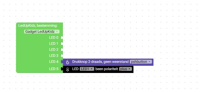
Then I made 3 effects
-Led ON -LED OFF -LED Fickers
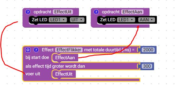
Then I made the code for the start
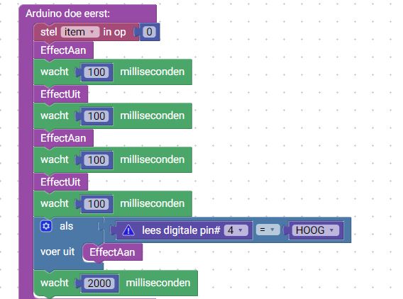
And after that the effect when i push the button.
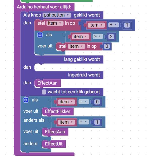
This is the code that this blokkencode generated. i copy paste this in arduino and send it through the arduino to the hello world board.
// Prototype wiring of the LED0 to 5
/*int LED0 = 2;// RESET
boolean LED0_ON = LOW;
int LED1 = 3;// SCK
boolean LED1_ON = LOW;
int LED2 = 4;// MISO
boolean LED2_ON = LOW;
int LED3 = 5;// MOSI
boolean LED3_ON = LOW;
int LED4 = 6;// PB4
boolean LED4_ON = LOW;
int LED5 = 7;// PB3
boolean LED5_ON = LOW;
*/


int item;
int pshbutton = 4;
int LED1 = 3;
boolean LED1_ON = HIGH;

boolean pshbutton_PRESSED = LOW;

long pshbuttonbuttonTimer = 0;
#define pshbuttonminShortPressTime 80
#define pshbuttonlongPressTime 750
boolean pshbuttonbuttonActive = false;
boolean pshbuttonlongPressActive = false;
#define pshbuttonNOPRESS    0
#define pshbuttonSHORTPRESS 1
#define pshbuttonLONGPRESS  2
int pshbuttonPressType = pshbuttonNOPRESS;

// Alle LED uit
// All LED off
void EffectUit() {
  digitalWrite(LED1, ! (LED1_ON));
}

// Alle LED aan
void EffectAan() {
  digitalWrite(LED1, LED1_ON);
}

int ard_effect0_status = -1;
unsigned long ard_effect0_start, ard_effect0_time;
#define EFFECT0_PERIOD 2000
#define EFFECT0_1_DURATION 300

// Deze functie beschrijven...
void EffectFlikker() {
  //Variables of this effect are reffered to with ard_effect0
  boolean restart = false;
  ard_effect0_time = millis() - ard_effect0_start;
  if (ard_effect0_time > EFFECT0_PERIOD) {
    //end effect, make sure it restarts
    if (ard_effect0_status > -1) {
    }
    restart = true;
    ard_effect0_status = -1;
    ard_effect0_start = ard_effect0_start + ard_effect0_time;
    ard_effect0_time = 0;
  }
  if (not restart && ard_effect0_status == -1) {
    ard_effect0_status = 0;
    ard_effect0_start = ard_effect0_start + ard_effect0_time;
    ard_effect0_time = 0;
  EffectAan();
  }
  if (ard_effect0_time > EFFECT0_1_DURATION && ard_effect0_status < 1) {
   ard_effect0_status = 1;
  EffectUit();
  }
}


void handlepshbuttonPress() {
  pshbuttonPressType = pshbuttonNOPRESS;
      if (digitalRead(pshbutton) == pshbutton_PRESSED) {
        if (pshbuttonbuttonActive == false) {
          pshbuttonbuttonActive = true;
          pshbuttonbuttonTimer = millis();
        }
        if ((millis() - pshbuttonbuttonTimer > pshbuttonlongPressTime) && (pshbuttonlongPressActive == false)) {
          pshbuttonlongPressActive = true;
          pshbuttonPressType = pshbuttonLONGPRESS;
        }
      } else {
        if (pshbuttonbuttonActive == true) {
          if (pshbuttonlongPressActive == true) {
            pshbuttonlongPressActive = false;
          } else {
            //avoid fast fluctuations to be identified as a click
            if (millis() - pshbuttonbuttonTimer > pshbuttonminShortPressTime)
              pshbuttonPressType = pshbuttonSHORTPRESS;
          }
          pshbuttonbuttonActive = false;
        }
      }
}


void setup() {
  pinMode(pshbutton, INPUT_PULLUP);
  pinMode(LED1, OUTPUT);
  ard_effect0_status = -1;
  ard_effect0_start = millis();


  item = 0;
  EffectAan();
  delay(100);
  EffectUit();
  delay(100);
  EffectAan();
  delay(100);
  EffectUit();
  delay(100);
  if (digitalRead(4) == HIGH) {
    EffectAan();
  }
  delay(2000);

}

void loop() {
  handlepshbuttonPress();

  if (pshbuttonPressType == pshbuttonSHORTPRESS) {
    //START STATEMENTS SHORT PRESS
    item = item + 1;
    if (item > 2) {
      item = 0;
    }
    //END  STATEMENTS SHORT PRESS
  } else if (pshbuttonPressType == pshbuttonLONGPRESS) {
    //START STATEMENTS LONG PRESS
    //END  STATEMENTS LONG PRESS
  } else if (!pshbuttonlongPressActive && digitalRead(pshbutton) == pshbutton_PRESSED) {
    //START STATEMENTS PRESS
    EffectAan();
    //END  STATEMENTS PRESS
  }

  if (item == 0) {
    EffectFlikker();
  } else if (item == 1) {
    EffectAan();
  } else {
    EffectUit();
  }

}
The result of this code:
final project
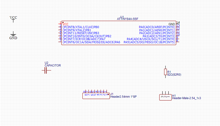
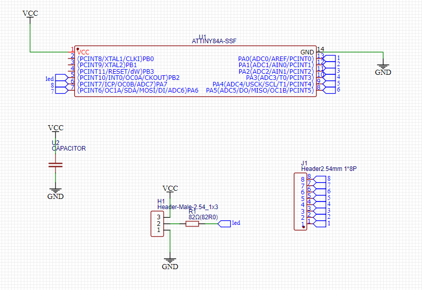
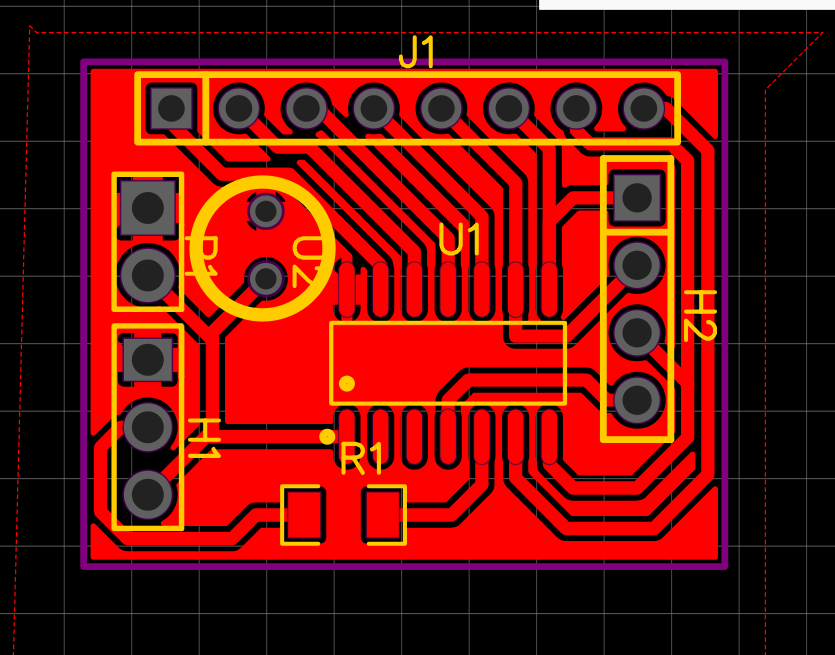
After testing with the arduino it was time to replace the arduino with its own pcb. After some consultation with some colleagues in the lab, I used easy EDA to draw this. As a microcontroller I used an ATtiny84 because it has enough programmable pins. This replaces the ardiuno. It needs 8 pins that gets a high or low signal and changes the pixel on the neopix accordingly.
Here i found the datasheet for the ATtiny84.
-
Port B is a 4-bit bi-directional I/O port with internal pull-up resistors (selected for each bit). The Port B output buffers have symmetrical drive characteristics with both high sink and source capability except PB3 which has the RESET capability. To use pin PB3 as an I/O pin, instead of RESET pin, program (‘0’) RSTDISBL fuse. As inputs, Port B pins that are externally pulled low will source current if the pull-up resistors are activated. The Port B pins are tri-stated when a reset condition becomes active, even if the clock is not running.
-
Reset input. A low level on this pin for longer than the minimum pulse length will generate a reset, even if the clock is not running.
-
Port A is a 8-bit bi-directional I/O port with internal pull-up resistors (selected for each bit). The Port A output buffers have symmetrical drive characteristics with both high sink and source capability. As inputs, Port A pins that are externally pulled low will source current if the pull-up resistors are activated. The Port A pins are tri-stated when a reset condition becomes active, even if the clock is not running.
After some feedback fom my colleages i worked wit easyEDA. With this programe i had less problems finding the right footprints than in KICAD. I made a new board:
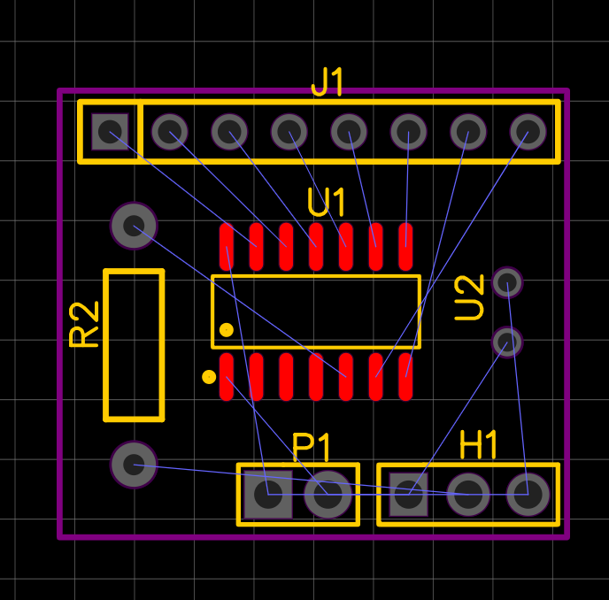
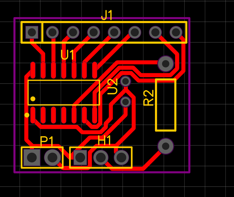
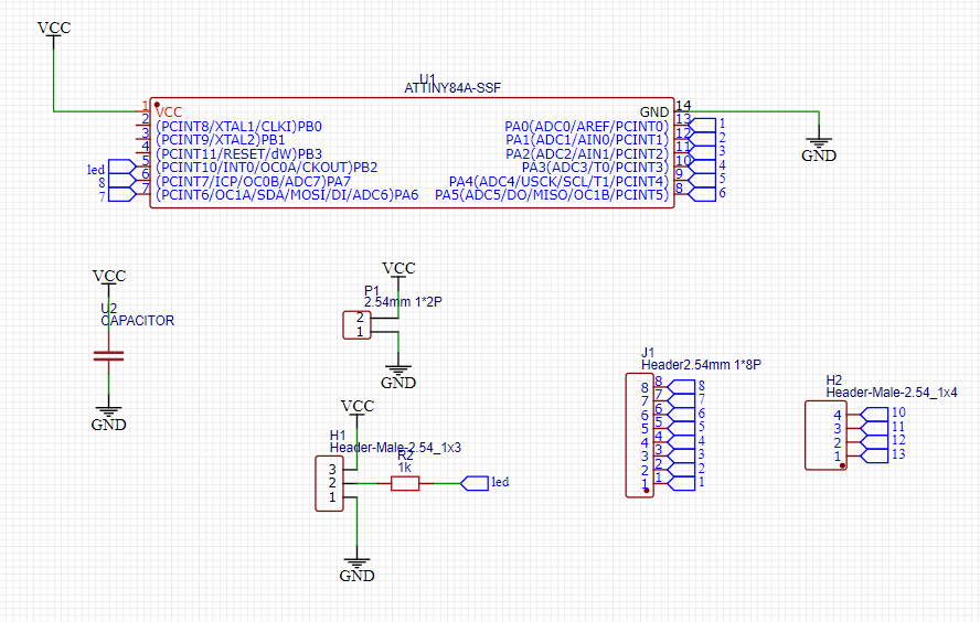
I started milling the same way i did in week 5
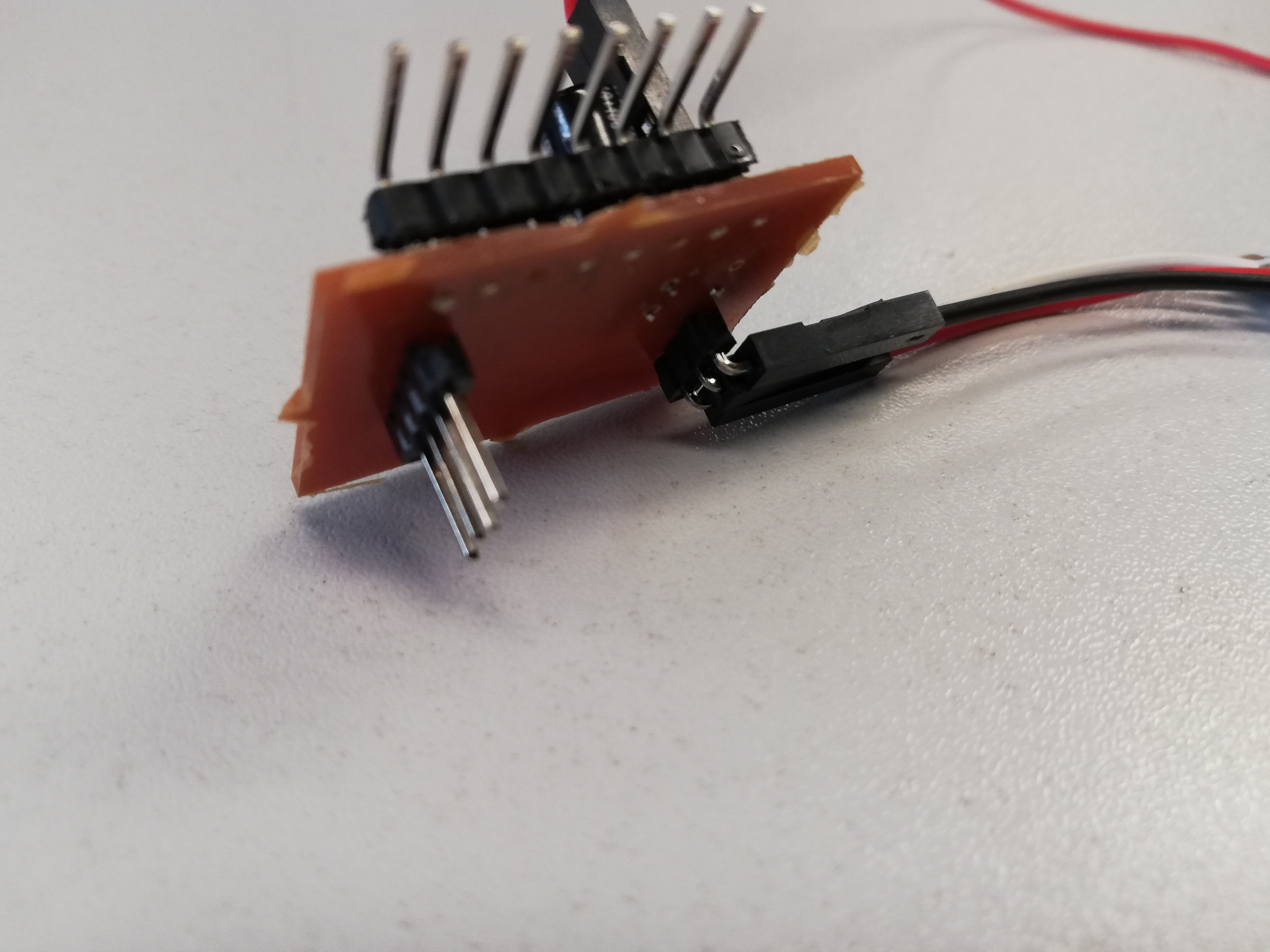
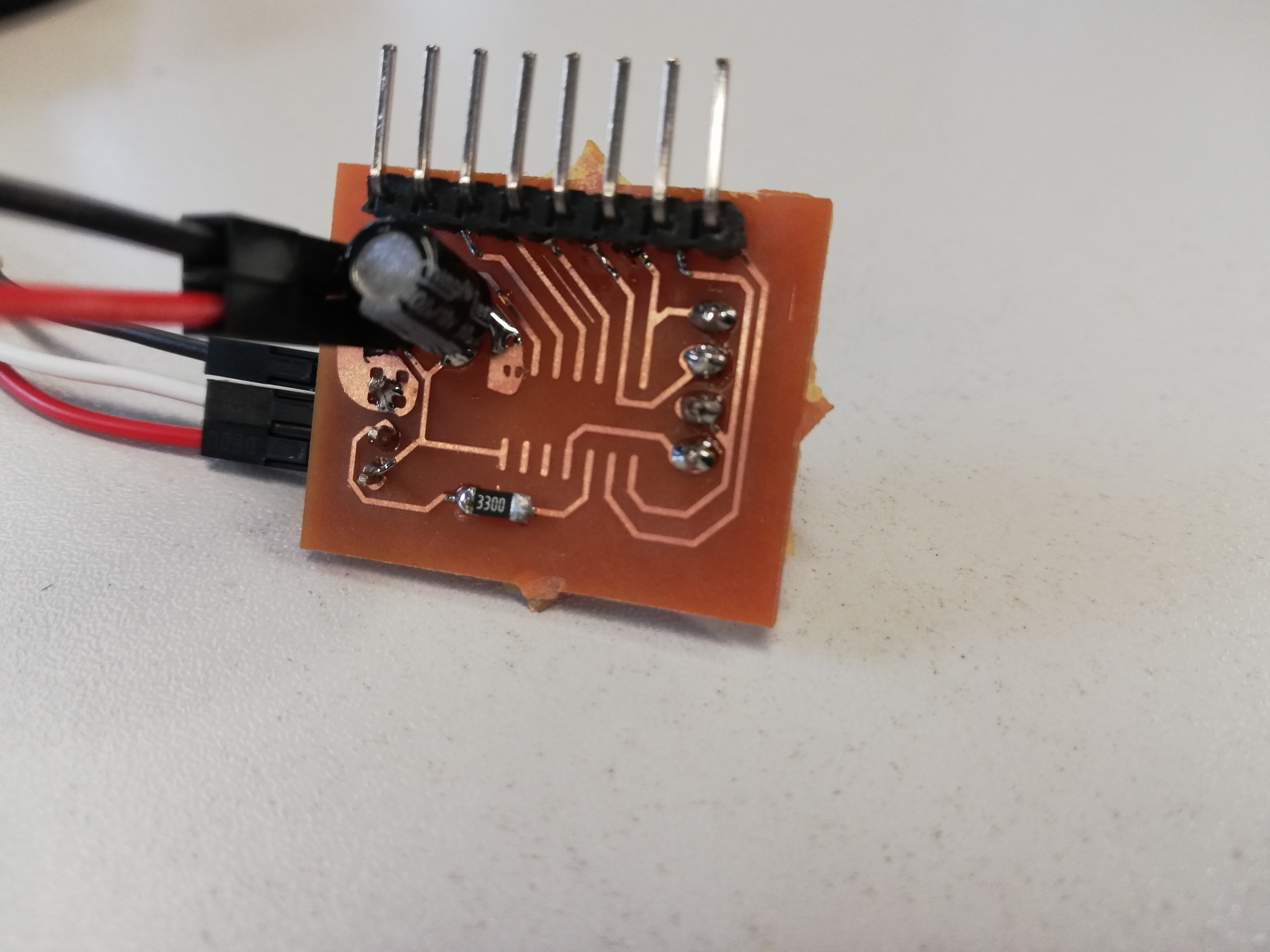
I soldered the components on it. I am just waiting for the microcontroller.
### link the the group assigment