9. Mechanical design/machine design
This week we worked on designing a machine that includes mechanism+actuation+automation. We started with building the mechanical parts and operating it manually, and then proceeded to actuating and automating the machine, and finally, documenting the group project.
The Fab Lab Dilijan Team teamed up with Iason Pantazis from Fab Lab Ioannina for this week’s project. Our team - Maro, Vachik, Narek.
And here’s a shot from the day leaving Dilijan at the end of the first week of break. As usual, snow likes to accompany us at the lab:

INTRO
The project that we chose to focus on this week was the wire bender. Wire bender is a machine that takes a wire (in our case with a diameter of 0.8 to 1 mm), and then bends it using a g-code that is fed to it. It can manufacture springs, wire frames inside to be used inside other object, paper clips… you name it.
There was a very good instruction set to make the machine authored by Jiri Praus, which made making the machine a very pleasant affair. The hardest part was sourcing the parts that could not be made in our fab lab in Dilijan, and having to scour the stores in Yerevan as well, and having to 3D print the V-grove welding machine feeding gear, which Iason designed.
Printing the parts
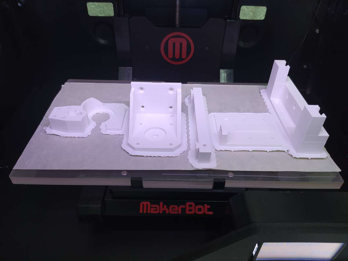
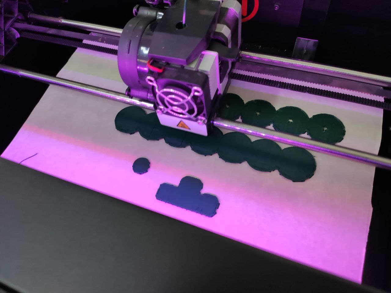
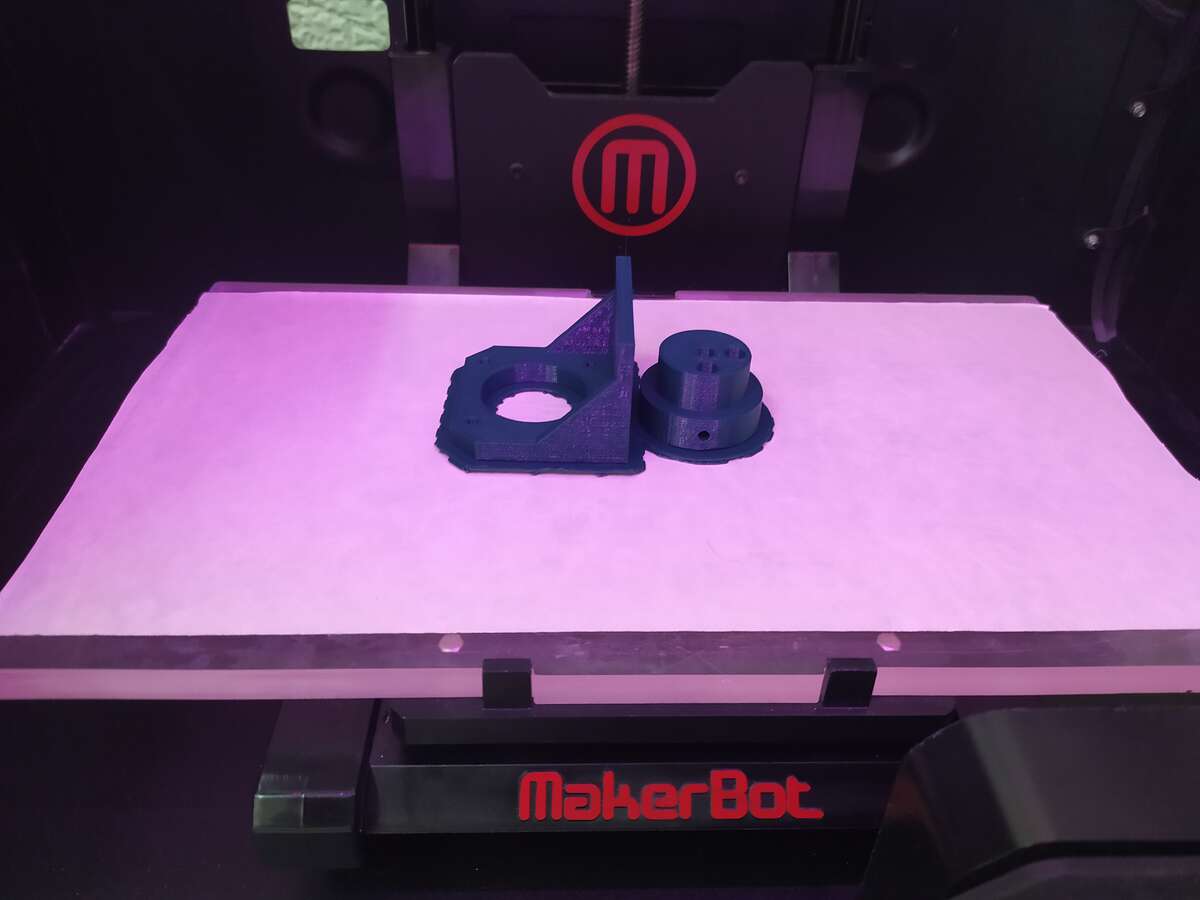
The parts were printed using the MakerBot 3D printers at Fab Lab Dilijan. Two colors were chosen for the design: White for most of the frames, and green for the rollers.
The masking tape used on the stages of the printers were changed and the printers leveled before printing. The first roller was printed standing up, so as to avoid PLA ‘dripping’ due to the sharp angles in the grove where the wire would have to sit. Unfortunately, the machine could not finish the first two rollers printed and would fail towards the top:
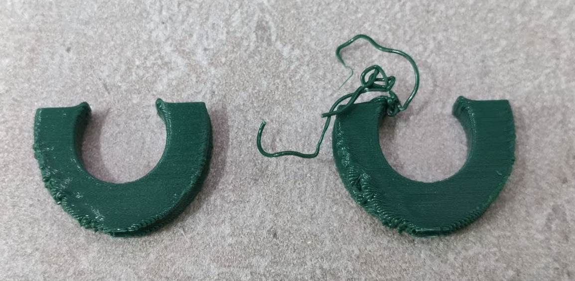
The temperature on the printer was then adjusted and lowered by 5 degrees, making it 215 degrees, and then the roller could be printed all the way to the top:
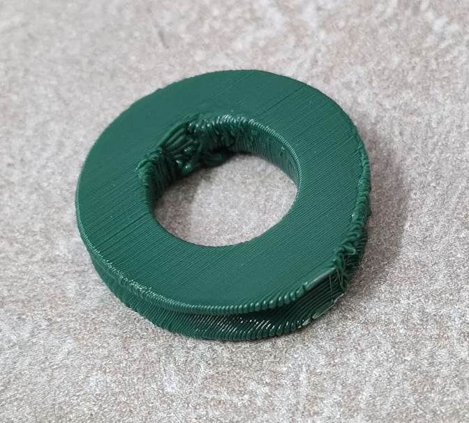
However, this proved to deform the shape of the circle inside, where bearings would have to be located. It was therefore decided to turn the rollers 90 degrees, and have them printed lying down. Surprisingly, this didn’t cause the wedges or groves to be distorted due to their sharp angles:
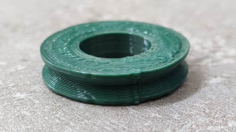
All the parts were scaled to 102% since the initial size of the rollers wouldn’t allow for the 3 mm bearing to fit in.
Here are the frames being printed:
Here are the rollers being printed:
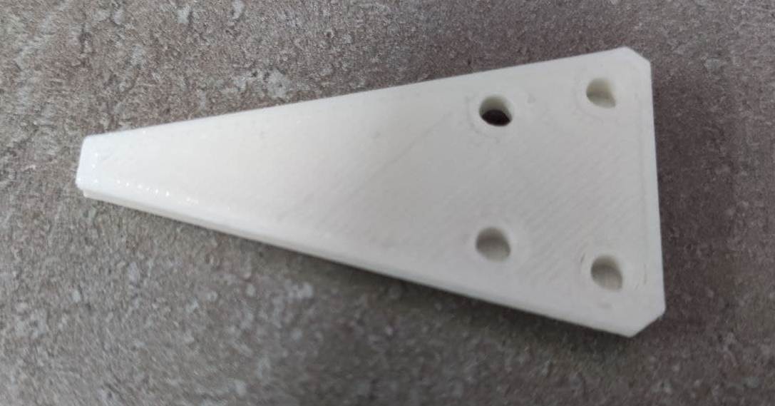
And here is the printed feeder piece:
Obtaining the other parts
As mentioned, most other parts had to be obtained from sellers in Yerevan, including the Arduino CNC shiels, bearing, and M3 bolts and nuts.
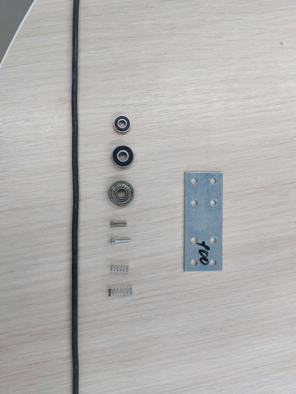
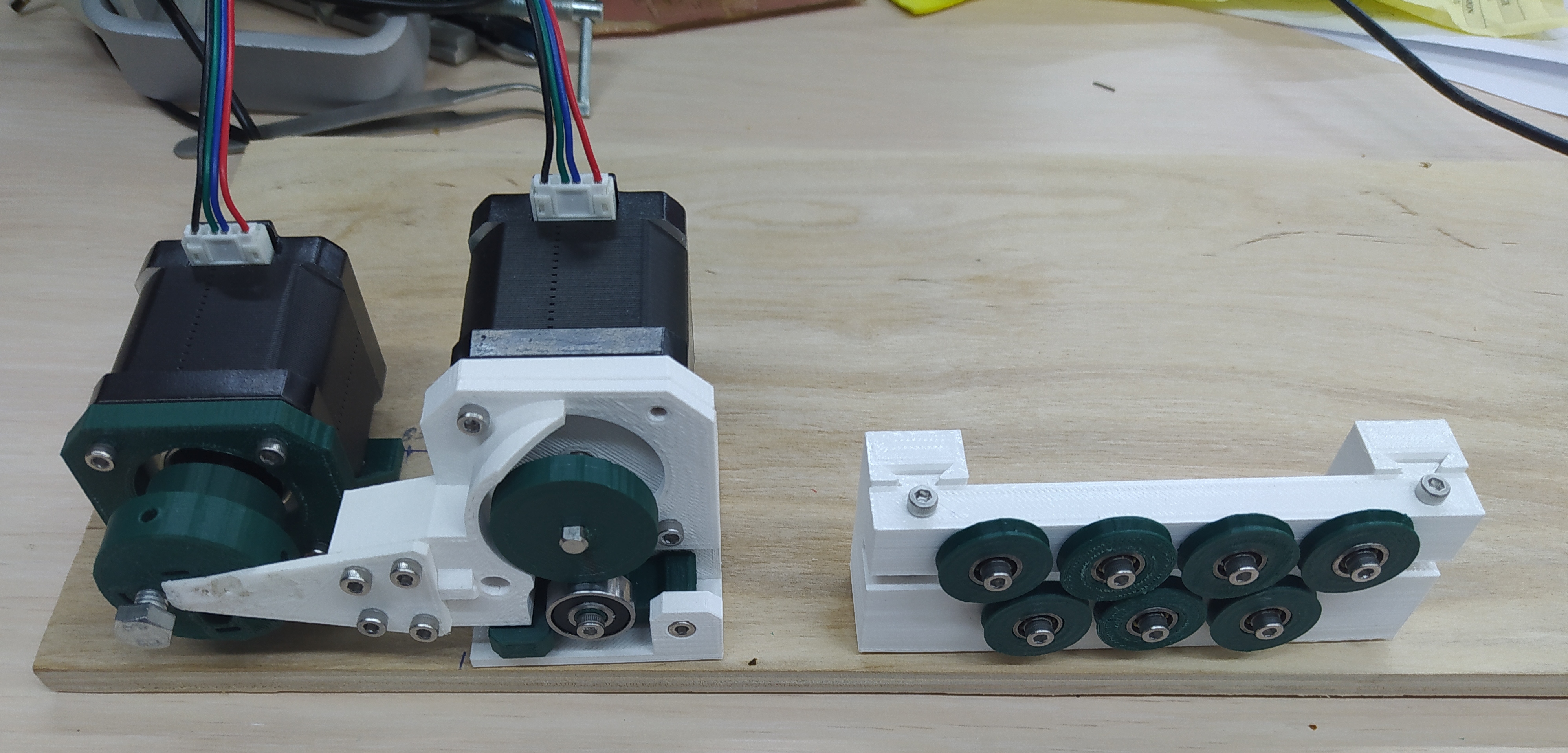
Here are some of the parts that could be obtained in Dilijan:
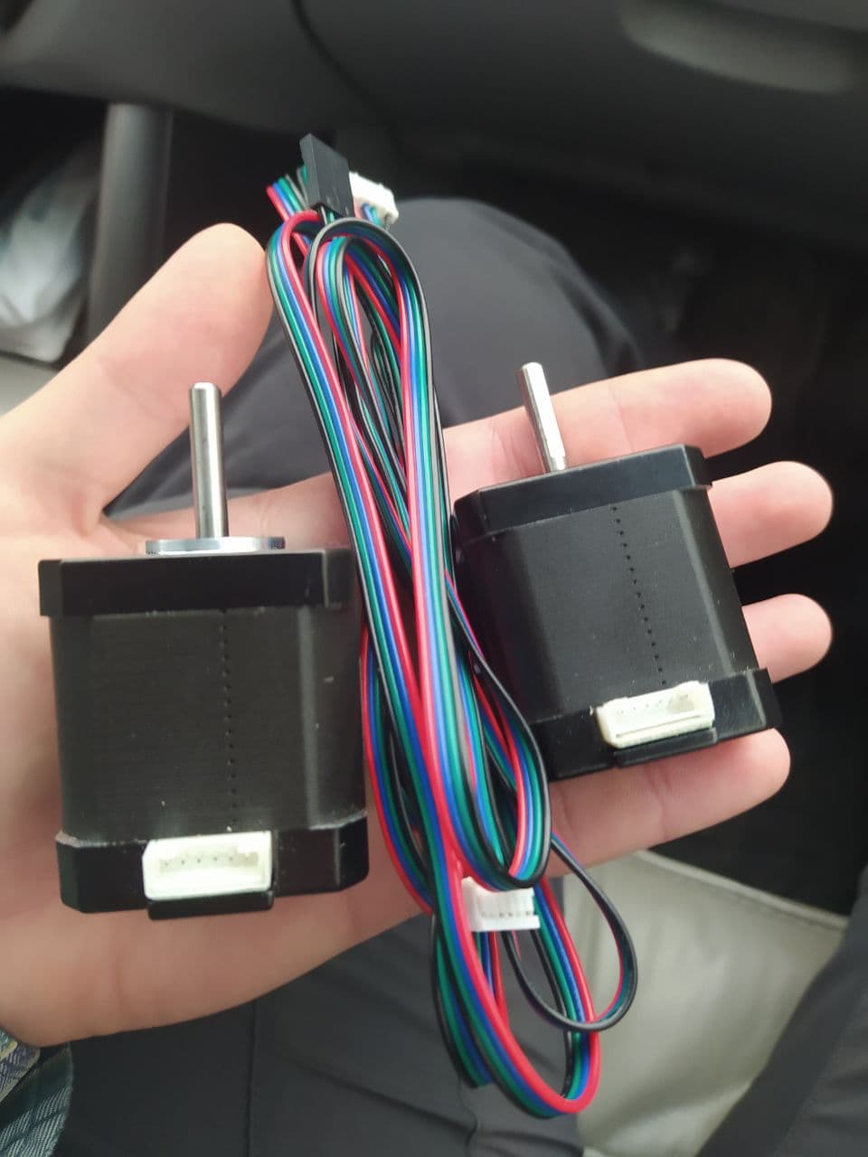
The two 17HS8401 stepper motors were also obtained from Yerevan:
Controlling the bender with Arduino
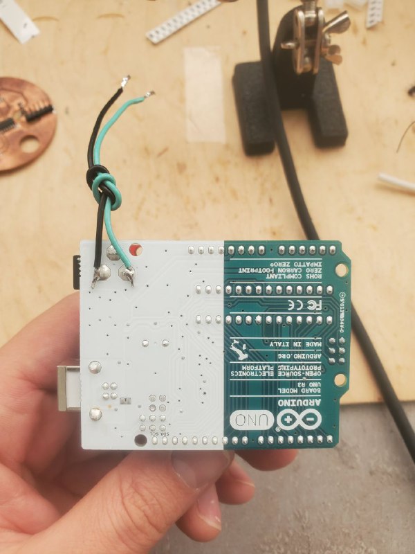
To control the stepper motors we used Arduino Uno. Arduino Uno board need CNC shield and stepper motor drivers to communicate with stepper motors. As we have 2 motors, we needed 2 drivers. At first we solder 2 wires to the Arduino Uno board, and connect them to the CNC shield (+ and - accordingly), which sits on top of the Arduino.
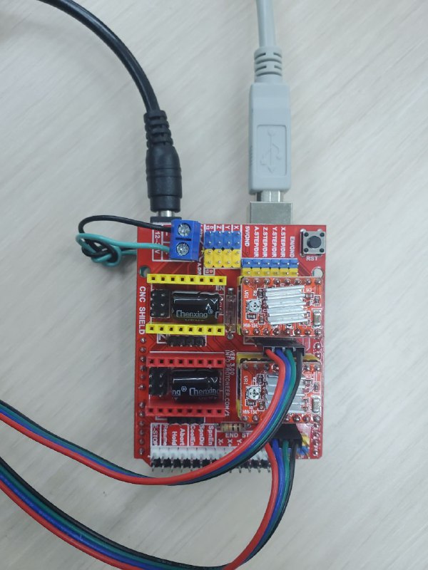
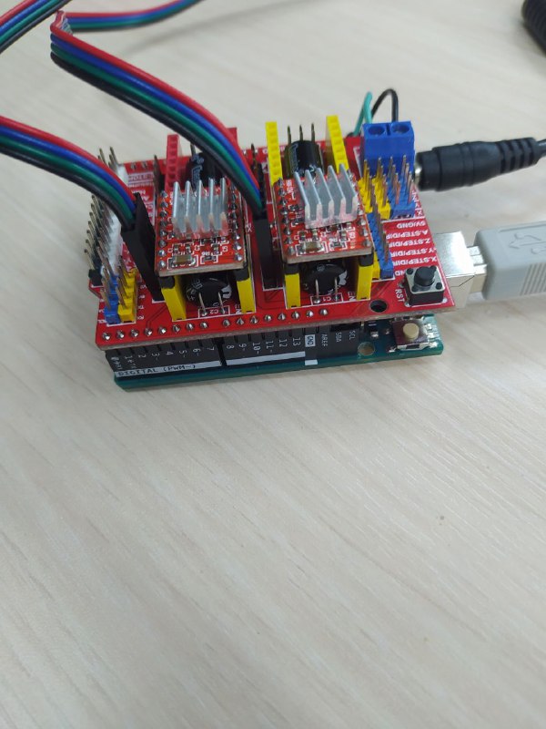
While putting the driver on the CNC shield, we had to make sure that EN (enable pin) on the diver and on the shield were connected to each other. So we placed one of the drivers on the X axis on the shield, and other to the Y axis.
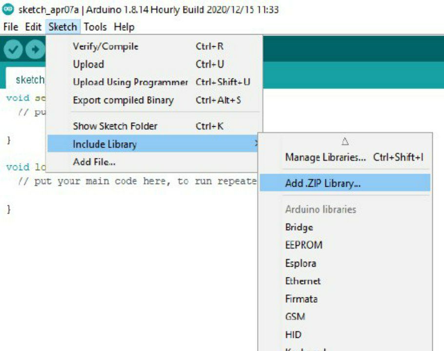
All the following steps are done with help of this tutorial. GRBL is a special library for arduino that “translates” G-code into electric signals, which then are sent to motors. To upload the GRBL library to the Arduino, at first we downloaded GRBL, then added it to the arduino software as shown below.
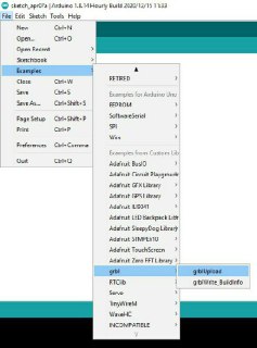
Then we just chose the upload grbl from examples and uploaded it on the arduino.
The software
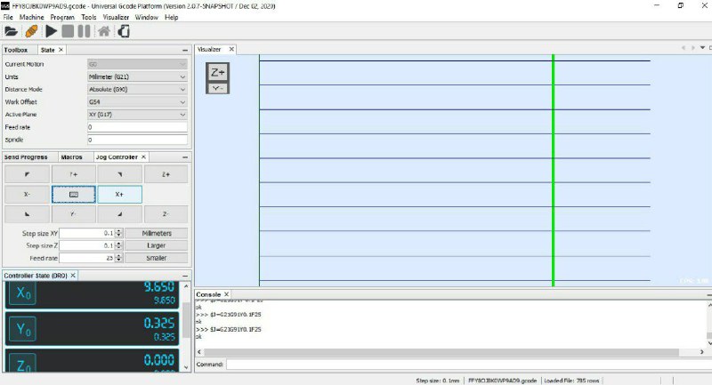
Then we downloaded software for communicating to arduino via G-code from here. This software allows us to send signals manually, or with G-code.
By clicking on X+ and X- buttons we can control one of the motors (depending which one is connected to X port on the CNC shield), and Y+ and Y- controls the other motor.
Wire bender in action
The finished machine:
Here’s how the wire bender is making a square spring:
Here’s a link to the video:
Future development
Various g-codes can be written to develop the project further in the future. An inside frame for an otherwise soft 2D model, various springs, hooks, nose wheel legs, wire undercarriage, and other interesting tidbits can be made with it.
The project can be developed to be able to bend wires in the third dimension as well, greatly enhancing its applications and the number of useful things that can be made with it.
Files
The 3D printer files for the parts are mainly included here. Make sure to increase the size by 2% to make sure the gears fit properly.
The 1 mm wire feeder part (which couldn’t be found in the stores and had to be 3D printed) designed by Iason Pantazis can be found here.
The g-code that was used can be downloaded from here.