4. Electronics production
This week we worked on characterizing the design rules for our PCB production process. That includes the feeds, speeds, plunge rate, depth of cut (traces and outline) and tooling.
For our PCB production, we used a Roland SRM-20 CNC milling device. The operation manual for it can be viewed here.
Design rules for printed cicuit-board production using Roland SRM-20
The feeds and speeds
The feed rate for the Roland SRM-20 as stated on p. 113 of its manual can be set through the Numerical Control (NC) or G-Code that is used for milling as follows:
Feed Rate (F) The range of the F parameter is as follows . Parameter : Feed rate
Function : Feed rate Acceptable range : Range 1 Valid range:
X and Y axes : 6 - 1800 mm/min (0.24 - 70.87 inch/min)
Z axis : 6 - 1800 mm/min (0.24 - 70.87 inch/min)
If the F code is omitted, the feed rate is set to 120 mm/min (4.72 inches/min). (p. 114)
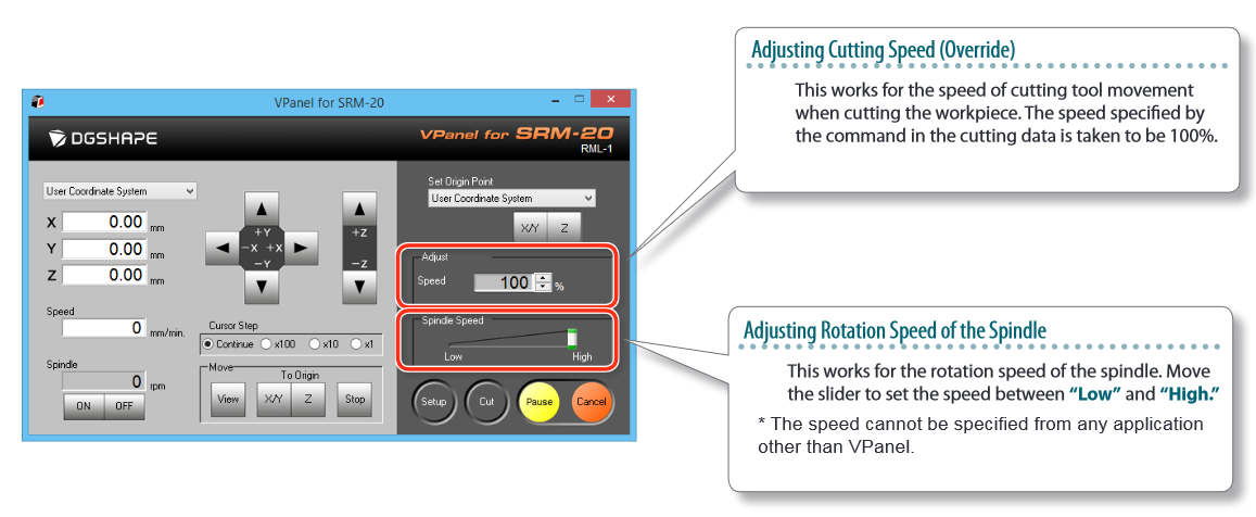
The machine used a software called VPanel for setup and operation. During the mill, the feed rate and spindle speed for the machine can be manually adjusted from the VPanel software using the following sliders, which configure it in terms of percentage of maximum feed/speed (from p. 106 of the manual):
Tooling
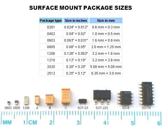
For PCB production during Fab Academy, the surface mount electronics package size that is used is 1206, for the parts to be large enough to allow for hand soldering of them to the board.
Therefore, the milling bits used should make it possible to have large enough conductive surfaces milled in the circuit boards that these parts can be hand soldered to. Therefore, the milling bits that are used are a 1/32” (0.79 mm) milling bit for milling around/cutting the PCB, and a 1/64” (0.40 mm) bit to mill the traces of the board.
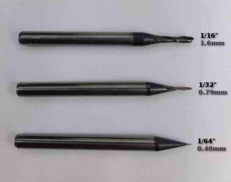
The bits are fit into the collet of the SRM-20 using a hex key. Special care must be taken when lowering the bits not to break or dent the head.
Depth of cut (traces and outline)
In order to assess the closeness of the traces that the machine can mill using the 1/64” milling bit, the following image was milled on a board to
perform a line test:
As can be seen from the test, when milling lines that are thinner than 0.001” from two sides, the mill can erase the line. See the jageddness around the thin
lines to the left of the image.
And also the 1/64” mill cannot cut lines smaller than 0.016”, which is to be expected as 1/64”=0.016”. This can be seen in the fact that only the rightmost five lines are visible at the top half of the image, and the same line has failed to be milled in the rest using the 1/64” mill bit.