12. Output Devices
individual assignment: add an output device to a microcontroller board you’ve designed, and program it to do something.
group assignment: measure the power consumption of an output device.
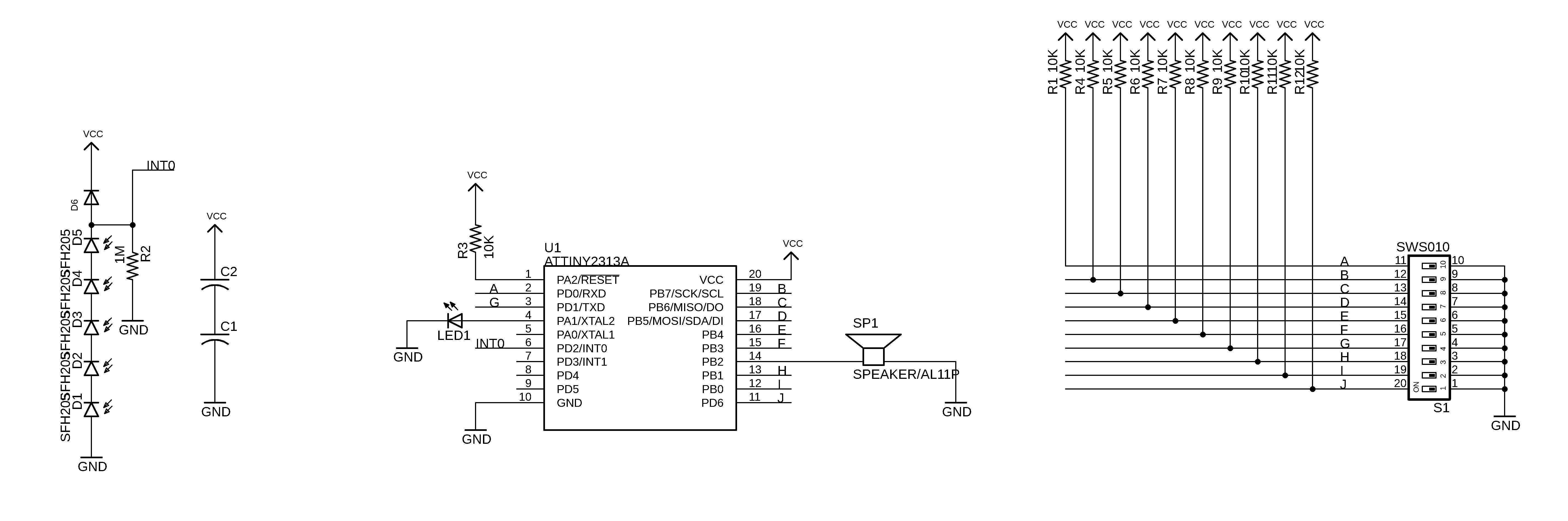
Here is the night piano schematic in eagle (there is no board version in Eagle of course because it is soldered a la freeform ;)
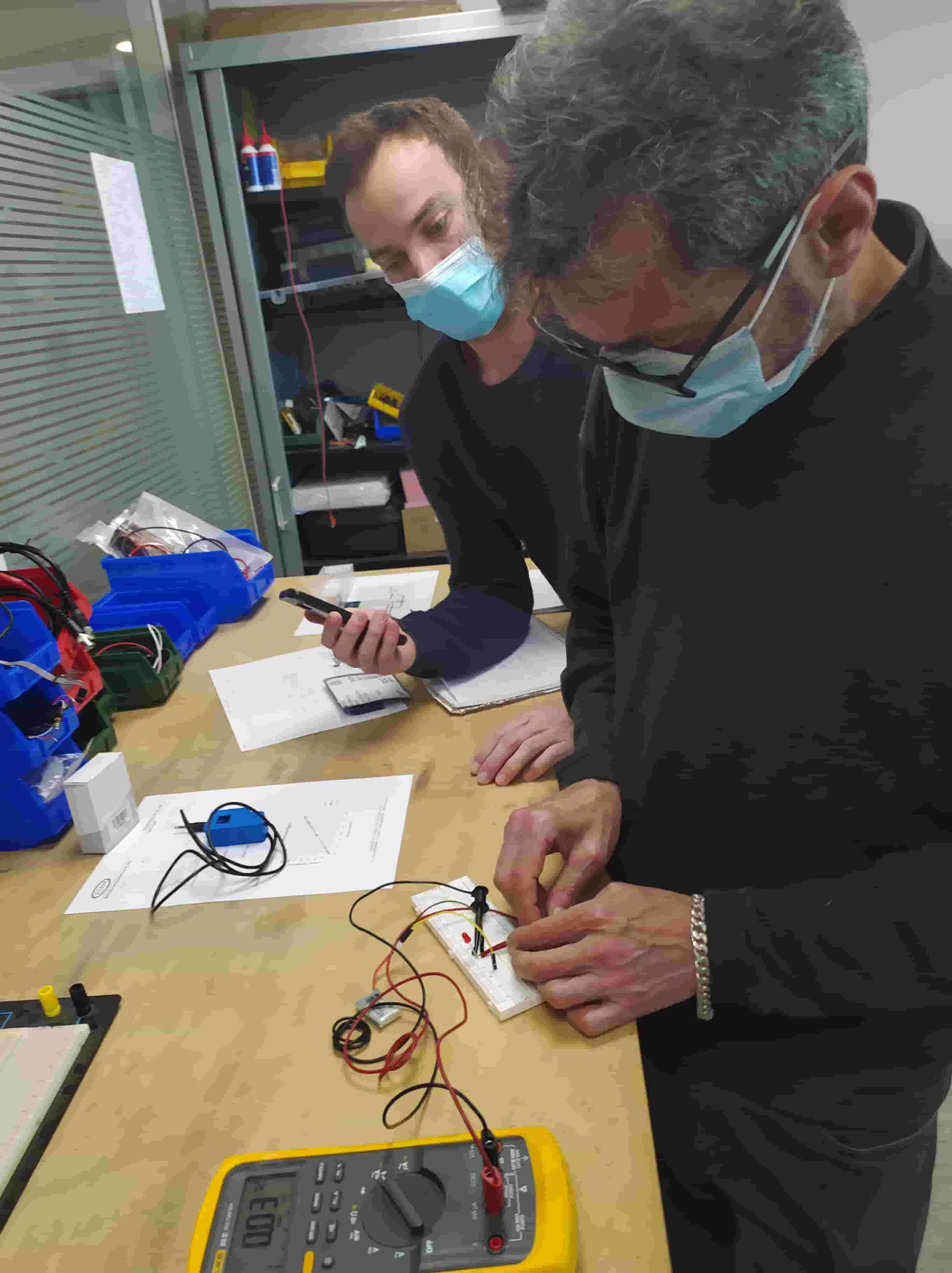
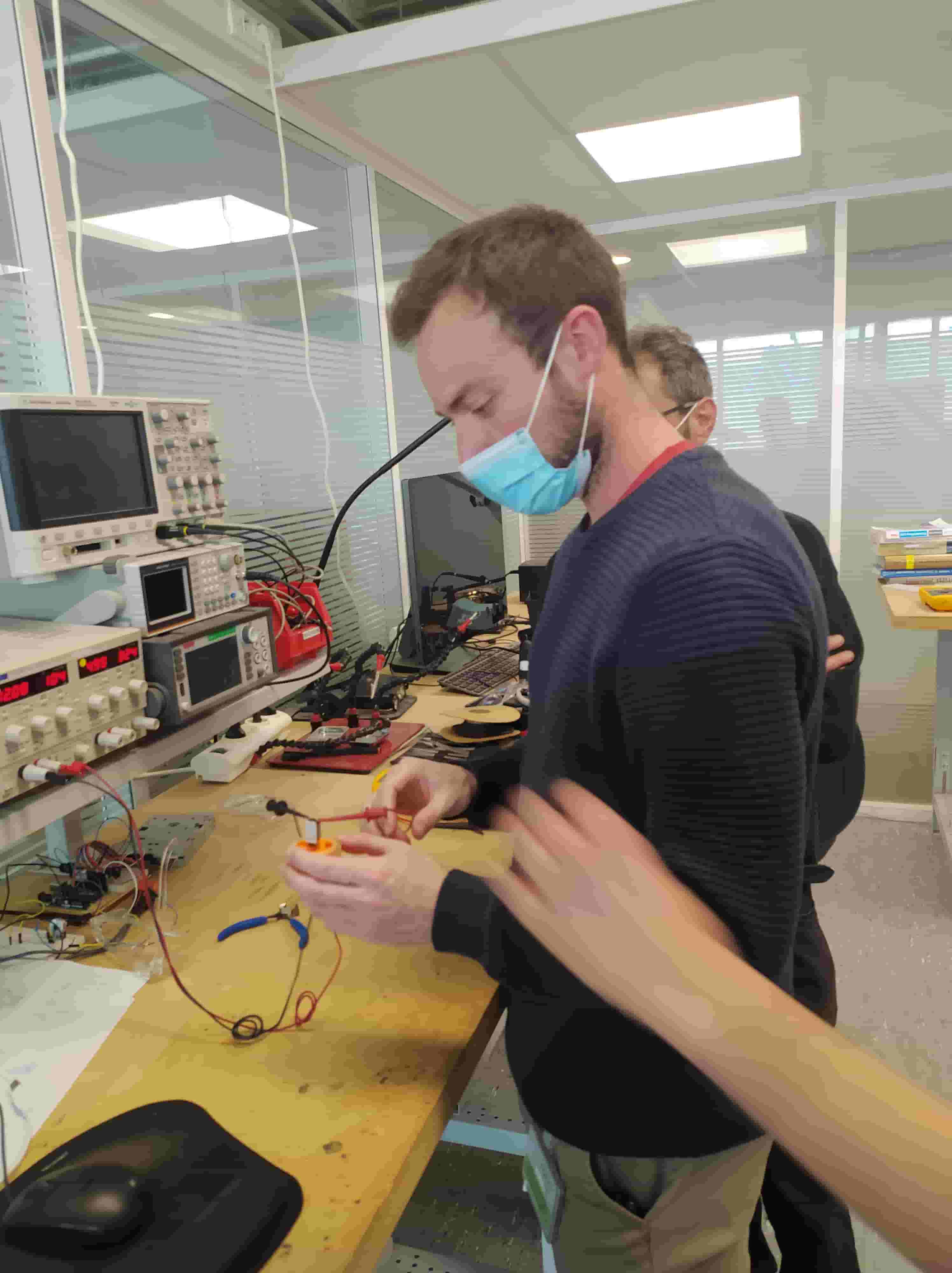
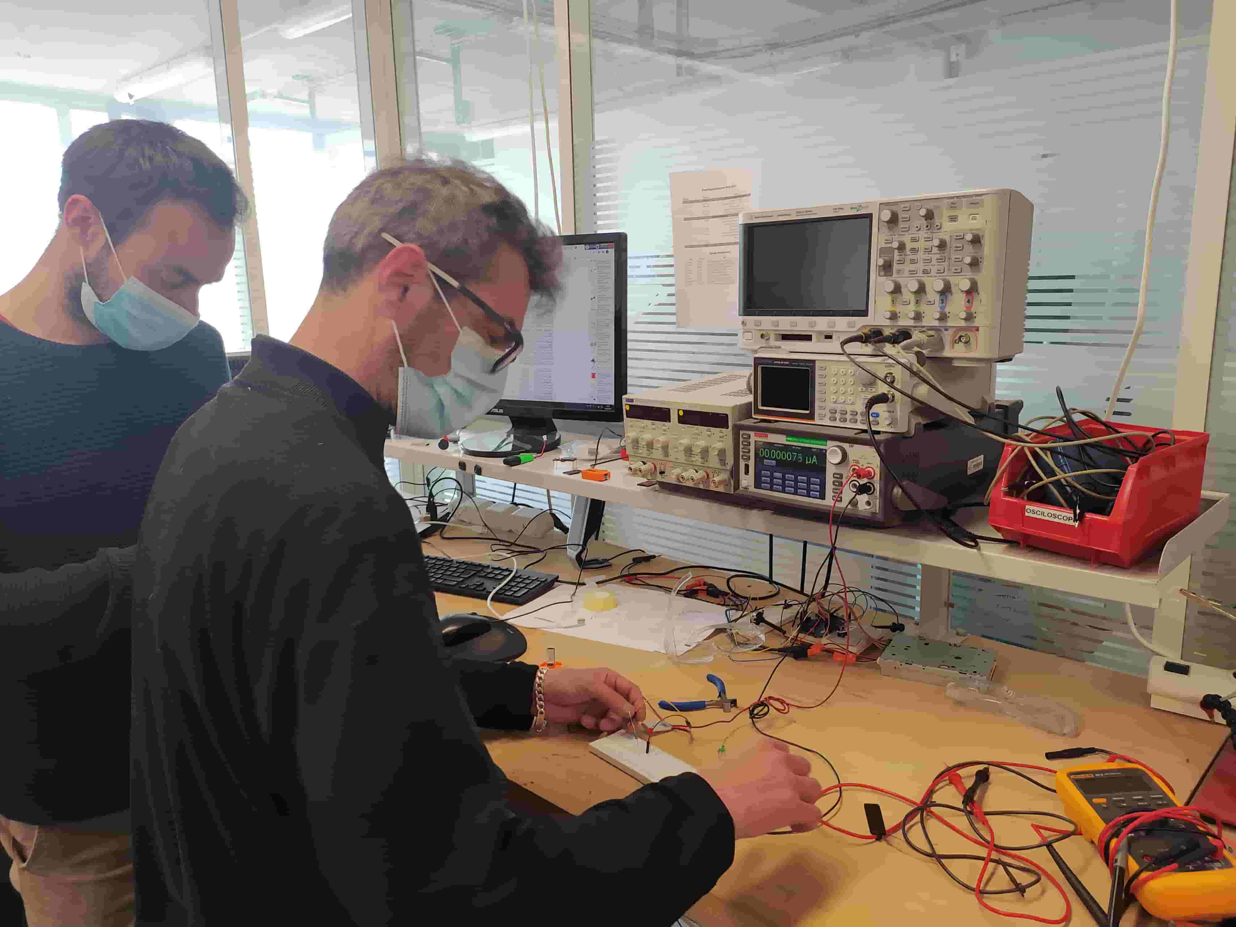
Group Project
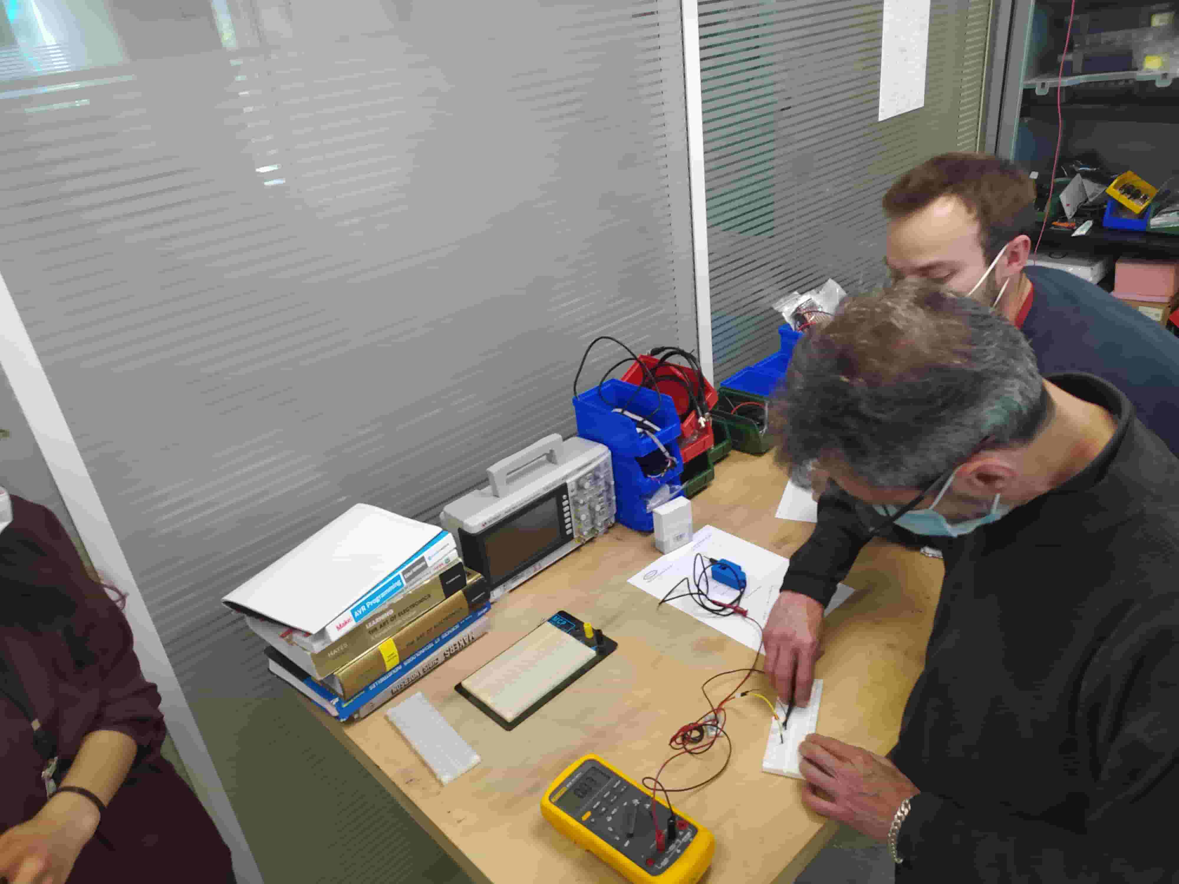
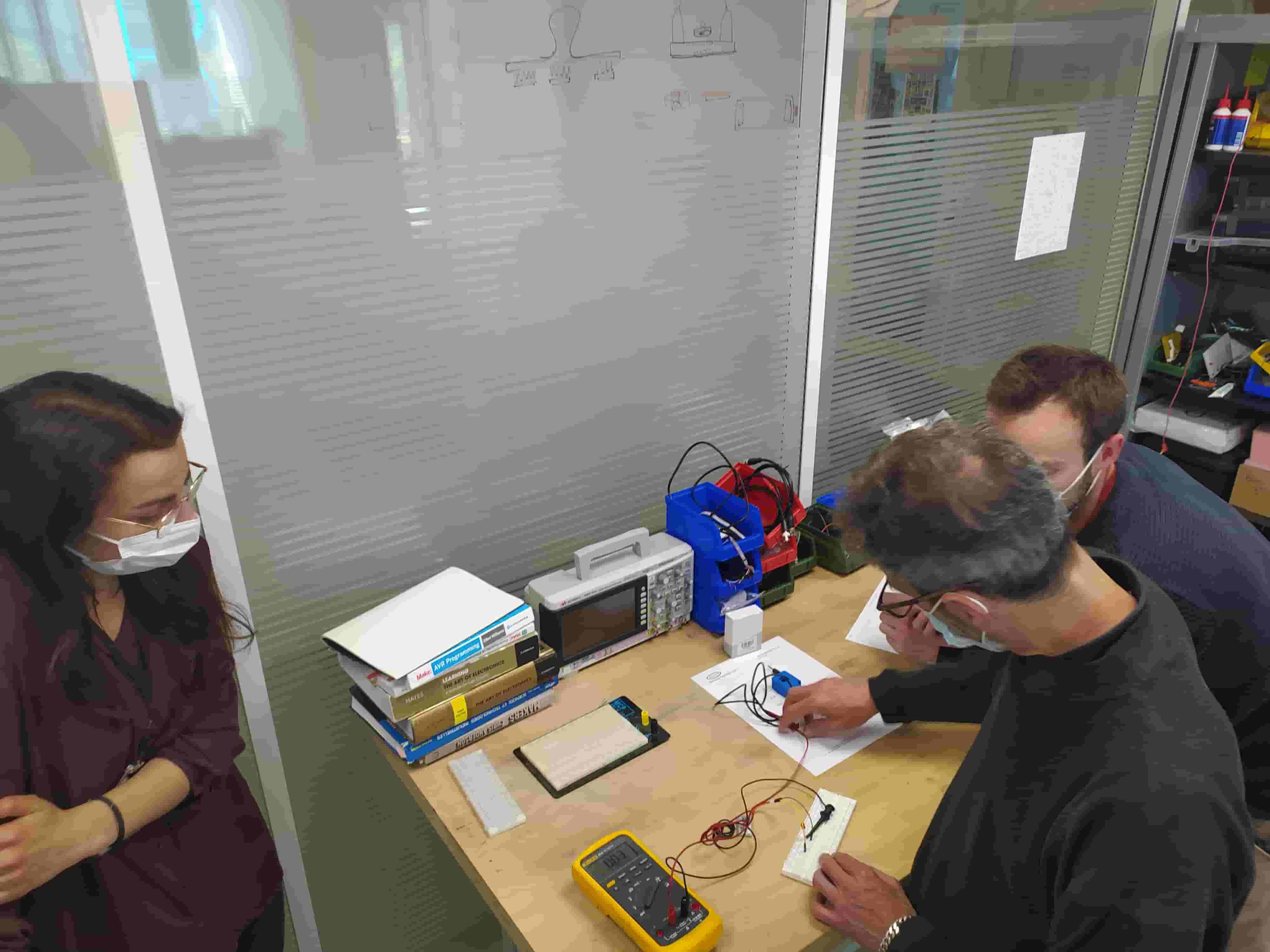
We looked at different ways of measuring current.
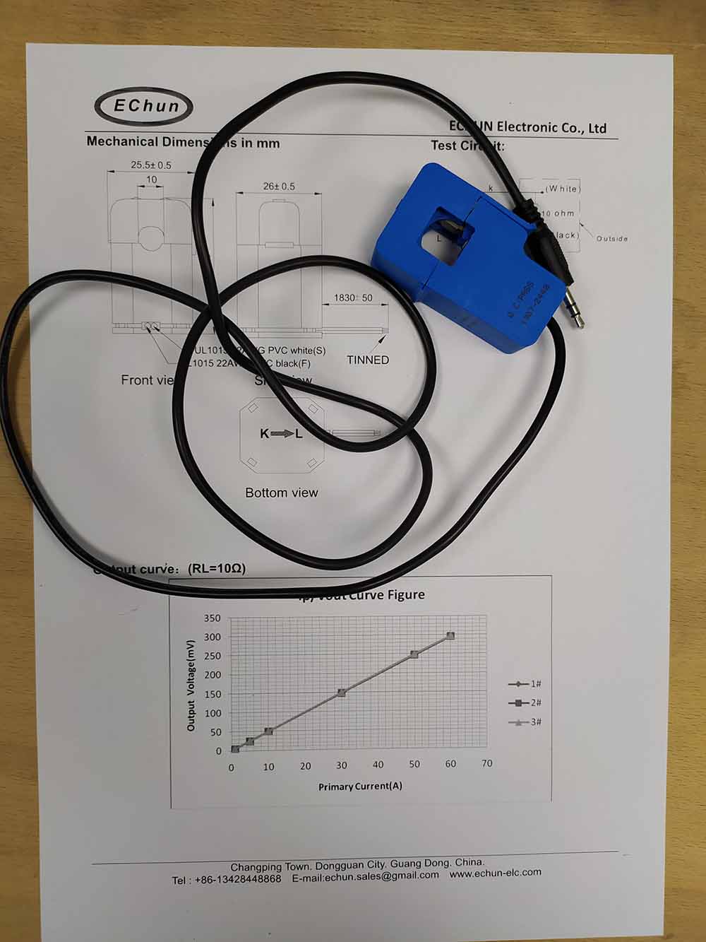
Using a non-invasive AC current sensor, we talked about how the two wires must be split to only sense one:
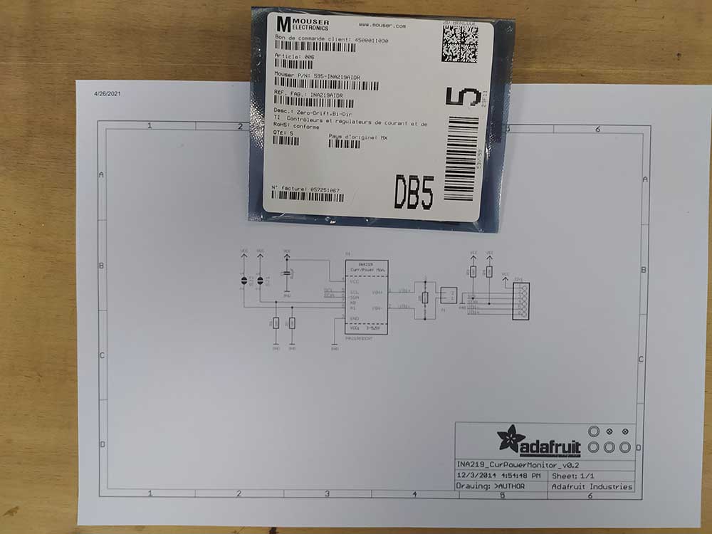
Using the INA219 current power monitor to do HIGH side current measurement:
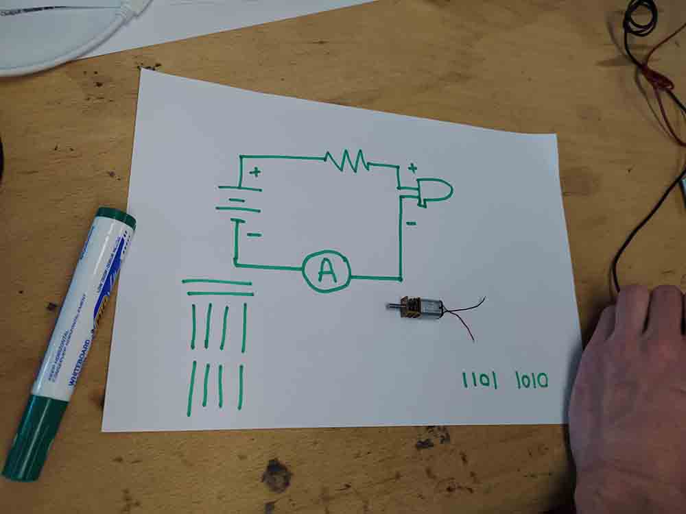
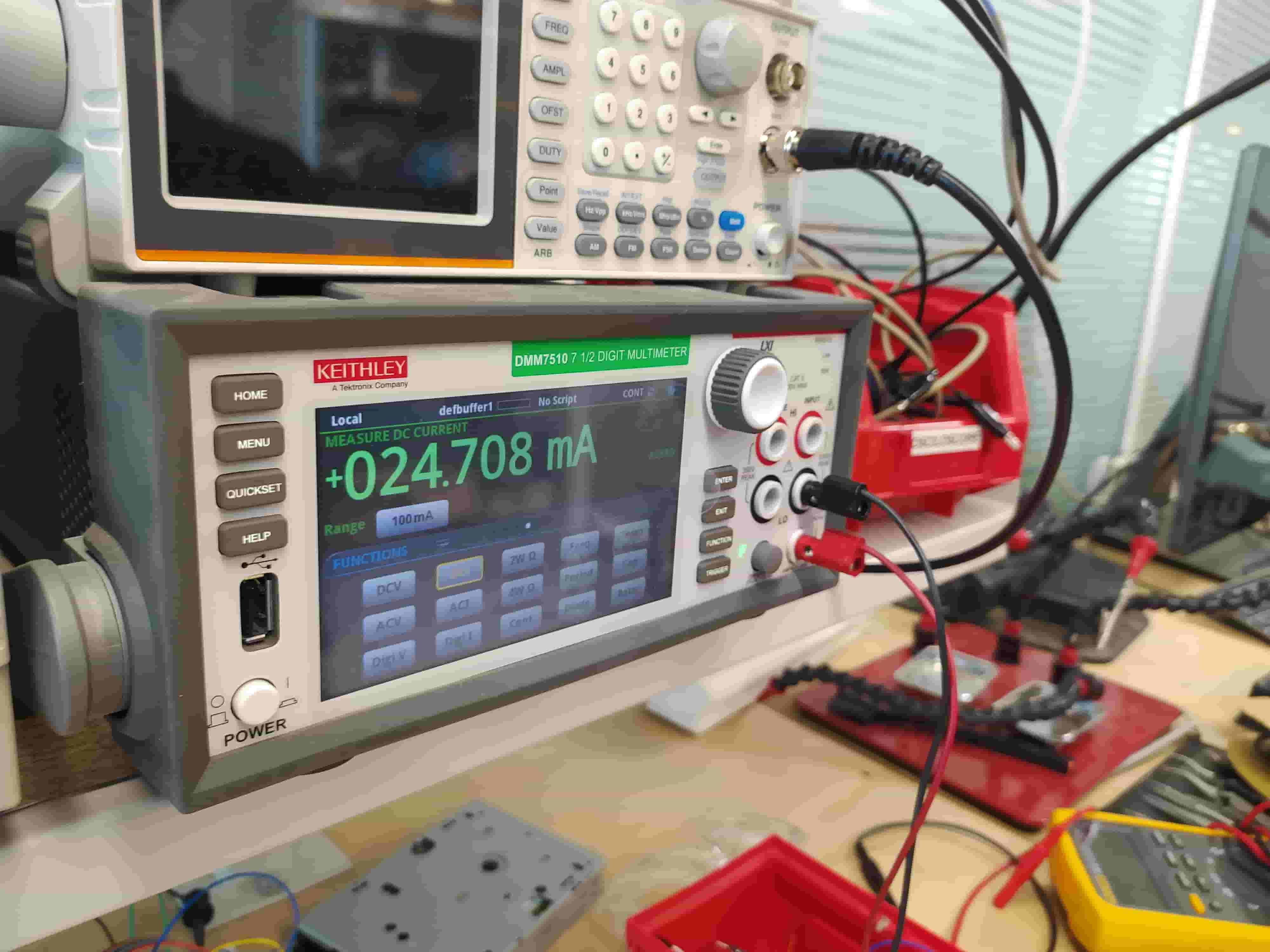
Using a multimeter in current detection mode. We saw that a red LED without a current limiting resistor draws 100mA and with a 55ohm resistor draws around 20mA.
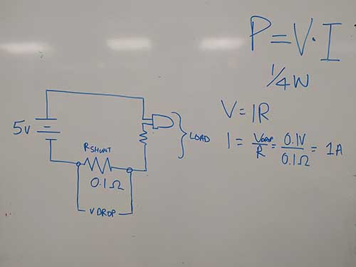
Use a shunt resistor and a microchip to detect the voltage drop across and thereby deduce the current with a known resistance.
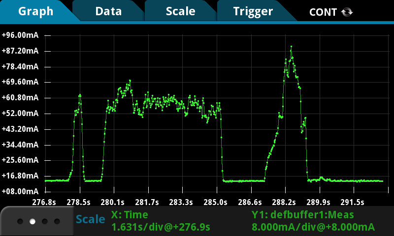
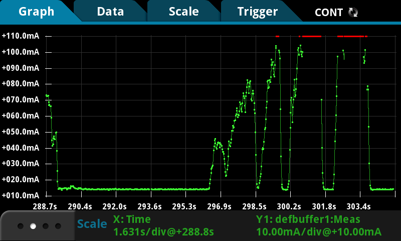
We then played around with the Keithley DMM7510 7 1/2 Digit Multimeter in current reading mode.
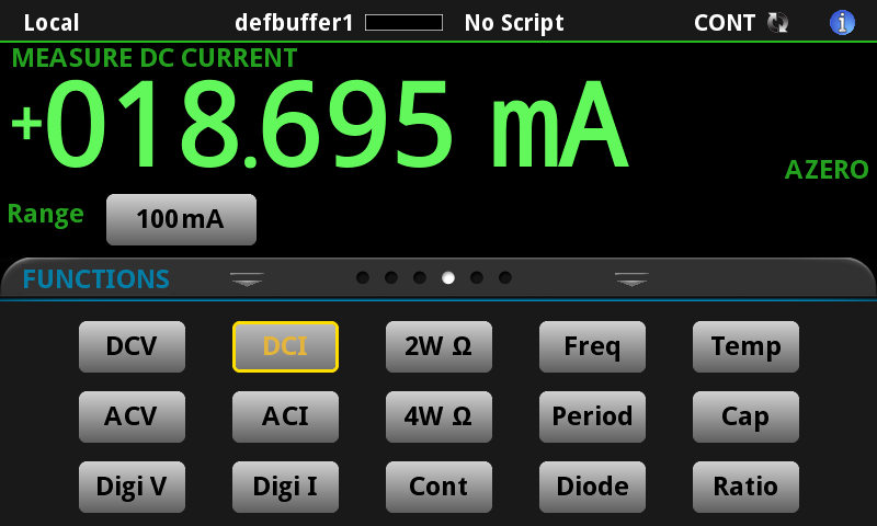

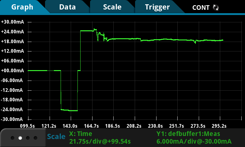
We saw the effect of increasing the resistance on a motor while its turning and created some graphs of this.
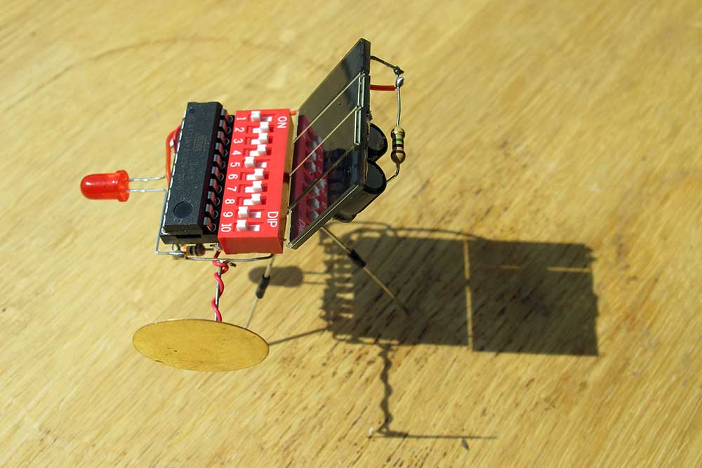
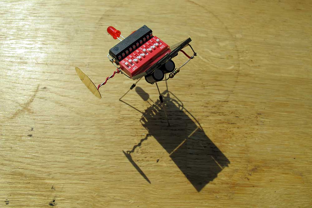
Night Piano
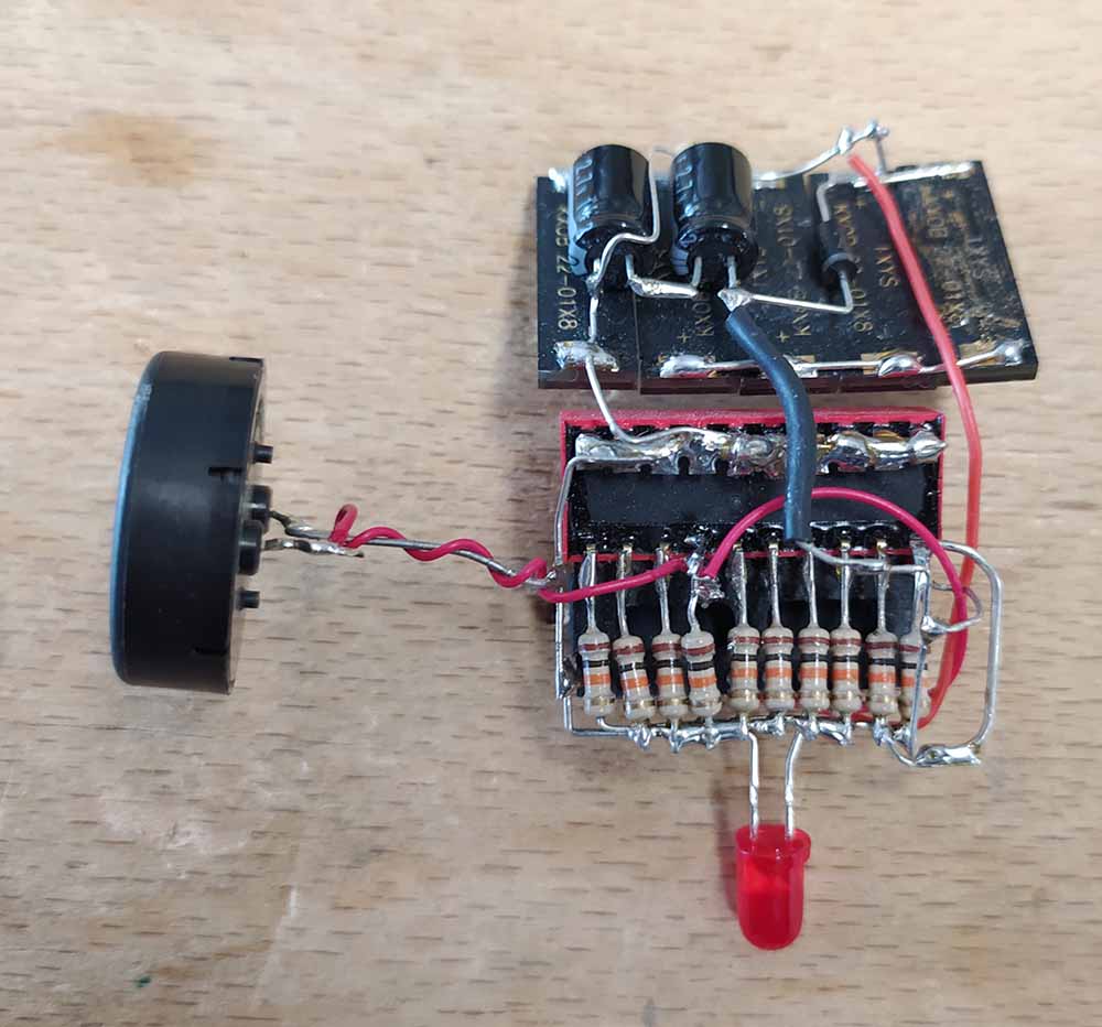
The night piano is a free-form soldered Attiny2313 circuit that charges up two supercapacitors during the day and plays a tune once night falls based on the combination of switches the user has selected.
Some more hero shots:
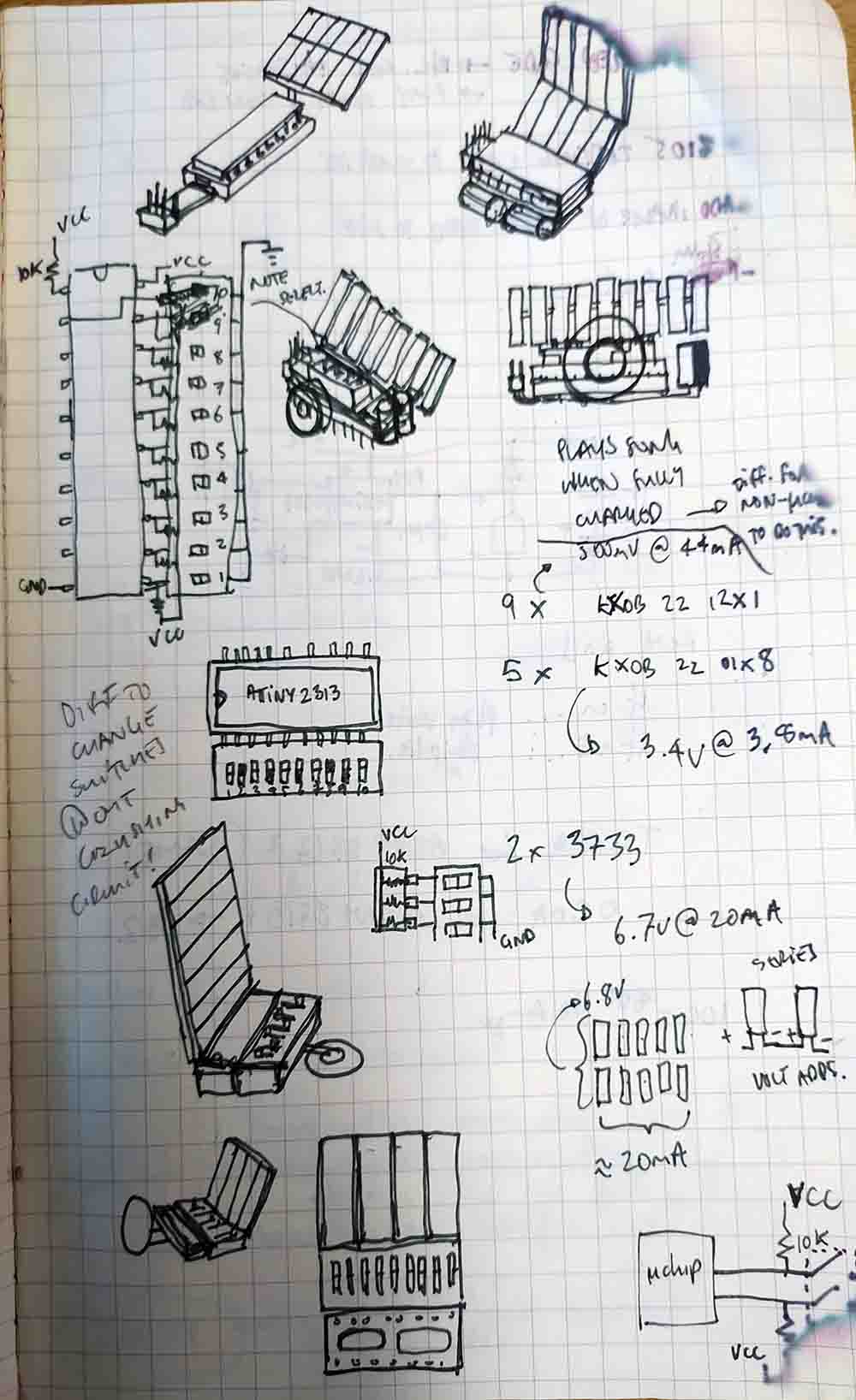
Here is my ideation:
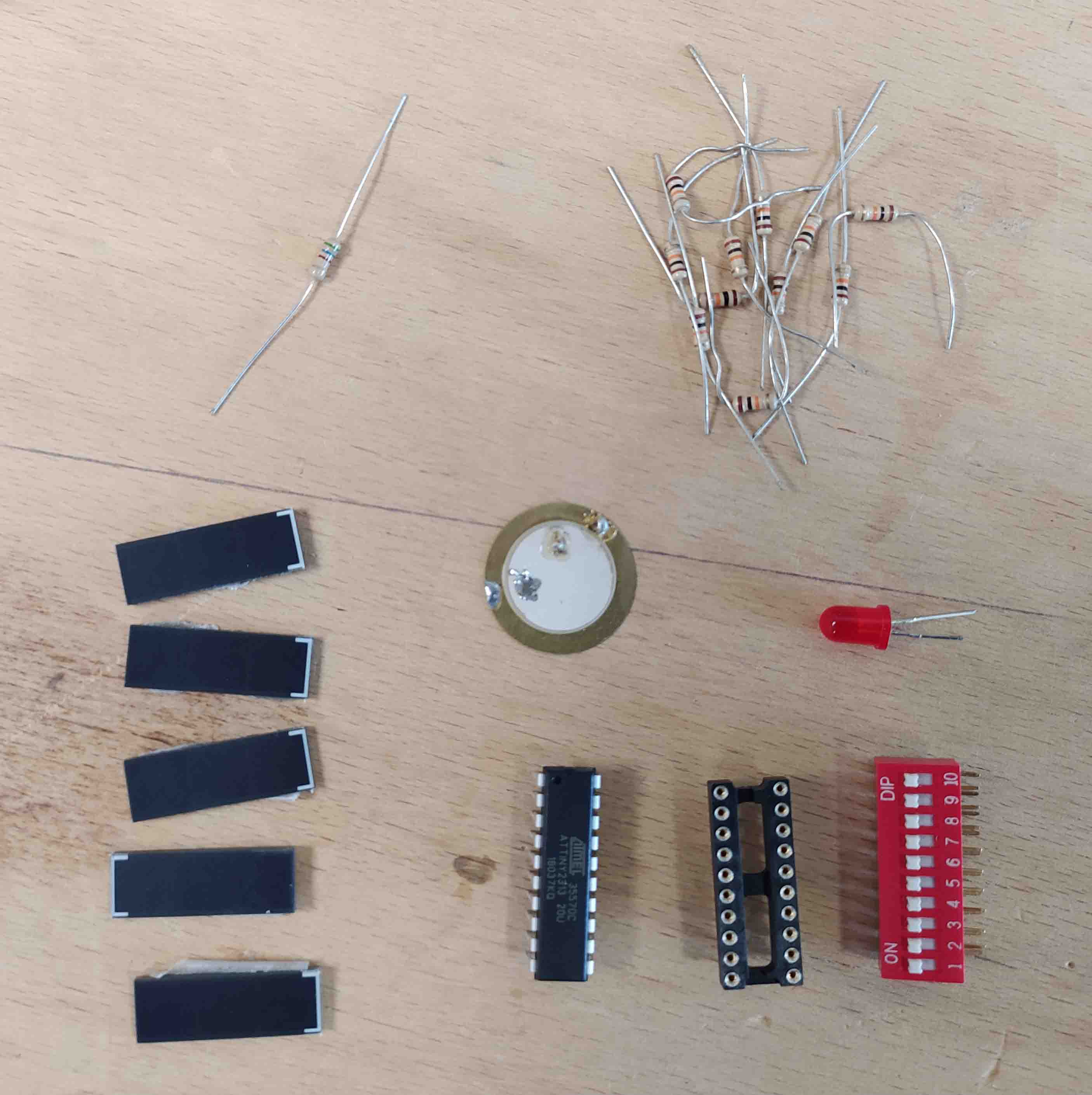
Here is the kit of parts:
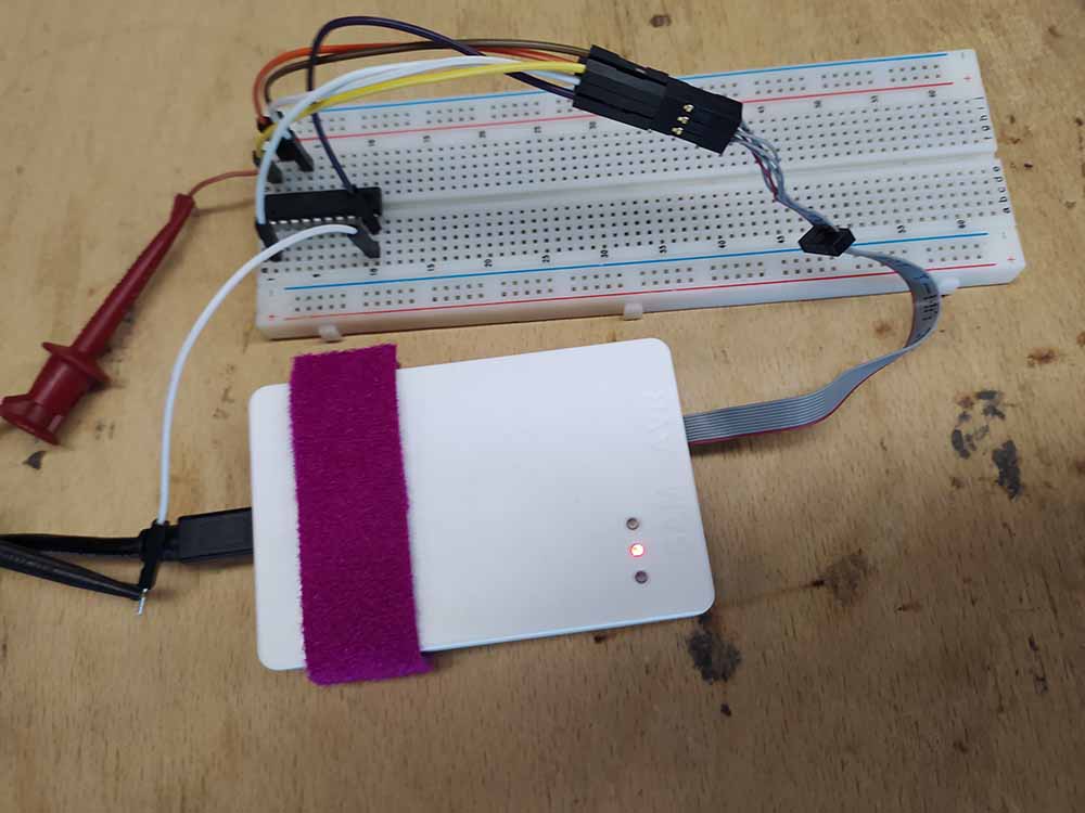
Here I am programming the Attiny2313 on a breadboard so I don’t have to solder an ISP.
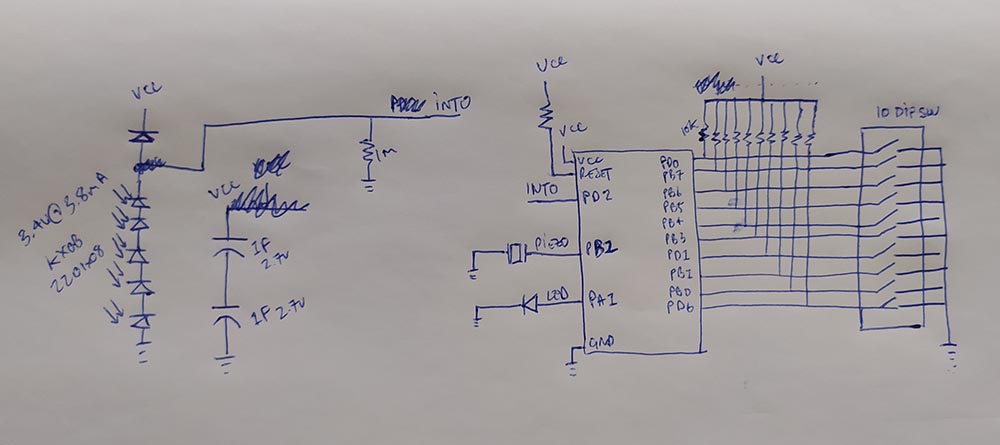
After I burned several solar panels by heating them beyond their peak temperature I eventually got five to work and soldered them together. It took a minimum of 5 panels to power 3.4V at 3.8mA.
I’m using the KXOB 22- 10x08s
The resistors are compressed but don’t make contact with the wires above.
I had to resort to wires in order to make some connections.
Here are the two sides combined together:
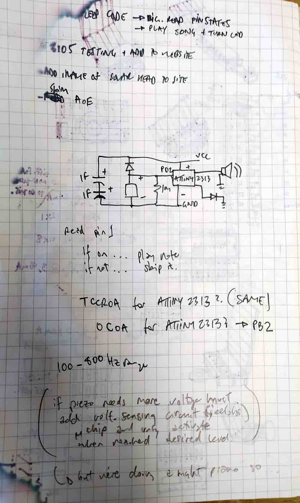
Here is the schematic hand drawn first:
And in eagle:
The charging circuit was from Evil Mad Scientist (https://www.evilmadscientist.com/2008/simple-solar-circuits/)
A charging diagram I made to explain how it works:
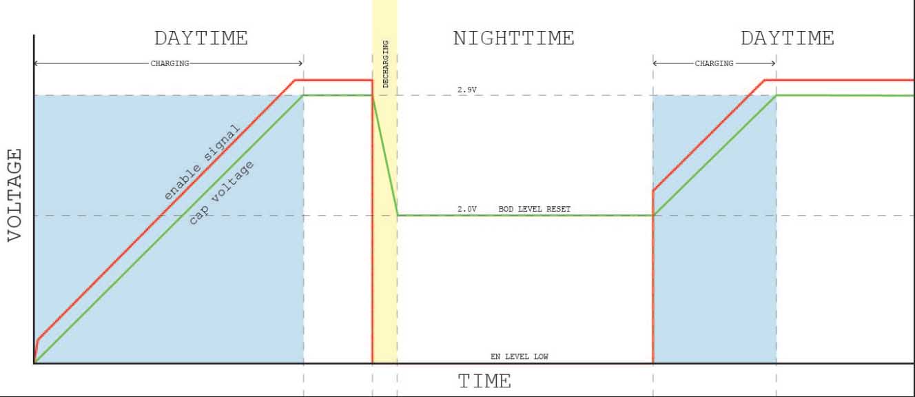
I have the Attiny2313 with BOD enabled and set to 1.7 and:
-Running the clock at 1MHz -Running at a lower voltage (AttinyVs can run on 1.8V, non-Vs can go to 2.7V) -Turn off Brown Out Detection (BOD) -Turn off ADC (in the Power Reduction Register) -Turn off Timers 0 and 1 (in the Power Reduction Register)
With these settings I have an Attiny84 drawing sub uA in sleep mode at 2.7V. This corresponds to the datasheet which states that the typical power consumption:
– Active Mode 1 MHz, 1.8V: 230 μA 32 kHz, 1.8V: 20 μA (including oscillator)
– Power-down Mode < 0.1 μA at 1.8V
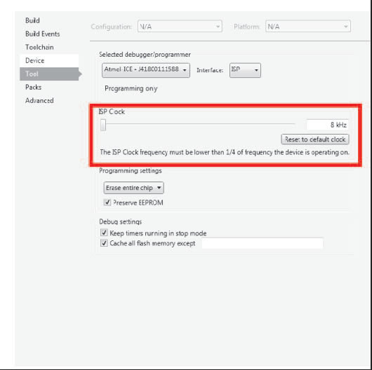
In order to get super low power consumption I reduced the Attiny2313 clock by a lot and therefore needed to change the communication speed for programming to 8KHz.
I have lowered the clock speed to 128KHz which necessitates changing the SPI clock speed in AVR Studio down to less than 1⁄4 of that speed. At 8KHz SPI seems to work. I am not dividing this 128KHz clock with the CLOCKDIV8 fuse.
Attiny2313’s absolute maximum Vcc rating is 6V. To avoid nearing this threshold I tried using smaller panels but this led to false triggering of the interrupt enable! I am now experimenting with putting two super caps in series to add the maximum voltage they can hold from 2.7V to 6.4V (closer to the maximum voltage that the panel is producing of 6.7V). I am assuming that the panel will probably never be able to power the capacitors up to 6.7V while the chip is suckling and considering that it gets harder to charge capacitors the more full they are (and these are supercaps!).
Another improvement could be having the 2313 wake up and then check the voltage of the capacitor using zero voltage power circuit developed by Jeelabs to decide whether it was a good thing it woke up or whether it might not just go back to sleep. I have not yet improved the efficiency of the Attiny2313 when it has been activated but at this point I don’t know what the application is (activate a mini robot sweeper for a few seconds, send out a series of nocturnal temperature transmissions, or something more connected to the fact that it has just gotten dark…).
Other options to lower power consumption include:
-using a series of rechargable NiCad batteries (1.2V each usually) in the place of capacitors,
-connecting the microcontroller to the enable low signal and then inverting it,
-using a more sophisticated IC like the LTC3105 solar harvester,
-having the microcontroller seperately powered with a smaller battery and a joule theif circuit,
Here is a nice analysis of power saving: https://sites.google.com/site/dannychouinard/Home/atmel-avr-stuff/low-power
Here is the code I developed using power saving techniques:
/*
 * sleep piano.c
 * ATTINY 2313
 * Author : FablabDigiscope
 */


#define F_CPU 1000000 // 1MHz: internal

#include <avr/interrupt.h>
#include <avr/sleep.h>
#include <util/delay.h>


void sleep()
{
    set_sleep_mode(SLEEP_MODE_PWR_DOWN); //select PWR DOWN, the most power savings
    sleep_enable(); //set  SE bit
    sei(); // enable global interrupts
    sleep_cpu(); //actually sleep
    sleep_disable(); //code reaches this point after interrupt
}


int main(void)
{
    //initialize Timer0 for playing piezo frequencies
    TCCR0A  |= (1<<COM0A0);  // toggle pin on match
    TCCR0A  |= (1<<WGM01);  // CTC mode (once hits OCRA)
    TCCR0B  |= (1<<CS00) | (1<<CS01); // Prescale: CPU 1MHz clock div. by 64 gets us in 100-800Hz audible range

    DDRA = 0b00000010; // LED output
    DDRB = 0b00000100; // piezo output and OC0A Timer0 output
    GIMSK |= (1 << INT0); // enable the INT0 external interrupt on pin PD2
    PORTA= 0b00000000; // LED off
    sleep();

    while(1) //this executes once awoken
{
    PORTA= 0b00000010; //LED on

    //read DIP switches in order from 1 to 10 = PD0, PB7, PB6, PB5, PB4, PB3, PD1, PB1, PB0, PD6,

    if ((PIND & (1 << PD0)) == 0)   //if switched on (grounded) play note
    {
        OCR0A = 0b00011001; // going up in intervals of 25 to get to 250 over ten notes
        _delay_ms(10);
    }

    if ((PINB & (1 << PB7)) == 0)   //if switched on (grounded) play note
    {
        OCR0A = 0b00110010; //50
        _delay_ms(10);
    }

    if ((PINB & (1 << PB6)) == 0)   //if switched on (grounded) play note
    {
        OCR0A = 0b01001011; //75
        _delay_ms(10);
    }

    if ((PINB & (1 << PB5)) == 0)   //if switched on (grounded) play note
    {
        OCR0A = 0b01100100; //100
        _delay_ms(10);
    }

    if ((PINB & (1 << PB4)) == 0)   //if switched on (grounded) play note
    {
        OCR0A = 0b01111101; //125
        _delay_ms(10);
    }

    if ((PINB & (1 << PB3)) == 0)   //if switched on (grounded) play note
    {
        OCR0A = 0b10010110; //150
        _delay_ms(10);
    }

    if ((PIND & (1 << PD1)) == 0)   //if switched on (grounded) play note
    {
        OCR0A = 0b10101111; //175
        _delay_ms(10);
    }

    if ((PINB & (1 << PB1)) == 0)   //if switched on (grounded) play note
    {
        OCR0A = 0b11001000; //200
        _delay_ms(10);
    }

    if ((PINB & (1 << PB0)) == 0)   //if switched on (grounded) play note
    {
        OCR0A = 0b11100001; //225
        _delay_ms(10);
    }

    if ((PIND & (1 << PD6)) == 0)   //if switched on (grounded) play note
    {
        OCR0A = 0b11111010; //250
        _delay_ms(10);
    }
}

}

ISR(INT0_vect) //PB2 level change
{
    //nothing
}
Here is the formula to calculate the lifespan of a supercapacitor once it is charged:
        C(Vs - Vf)
 T =    ----------
            I
T = Time in seconds C = Capacitance in Farads Vs= is initial voltage of cap in Volts Vf= is final voltage of cap in Volts I = Current draw in Amps
In our case, it would look something like this during sleep taking these from the Attiny2313 datasheet:
“Typical Power Consumption – Active Mode 1 MHz, 1.8V: 230 μA 32 kHz, 1.8V: 20 μA (including oscillator)
– Power-down Mode < 0.1 μA at 1.8V”
So, just the Attiny in active mode:
        1F (2.9V-1.8V)
 T =     ----------
         0.000230 A
T = 4782 seconds = 80 minutes = 1hr 20 minutes
What about just an LED:
        1F (2.9V-1.8V)
 T =      ----------
            0.02 A
T = 55 seconds! Not even a minute…
Adding a second supercapacitor gets us to 110 seconds only! Putting a second capacitor in parallel rather than series (to increase to max voltage), we could get up to 6.4V which gives us 230 seconds of LED blinking for an ideal capacitor.