9. Mechanical Design + Machine Design
group assignment:
- design a machine that includes mechanism+actuation+automation
- build the mechanical parts and operate it manually
- document the group project and your individual contribution
Files from this week’s content :
Here is the 3D parts to print :
I didn’t get a chance to work with the group on the machine as I am a co-instructor this year and I have little time to coordinate with students outside of courses that I am giving. This week I worked on an automatic syringe device which could be used to control a suction head on the machine. Here is a link to the Machine Design group project page:
http://academany.fabcloud.io/fabacademy/2021/labs/digiscope/site/Group-Assignments/week-09-GA-mechanical-and-machine-design/
CNC machines of the past:
I’m inspired by the work of Pe Lang:
I’ve also attempted to make a few CNC machines in the past. This platform is stationary and allows a solar panel to move to better face the sun. It uses stepper motors instead of DC gearmotors.
I’ve also made machines from e-waste:
A small plotter made from recycled E-Waste and controlled with GRBL.
Here is my instructable : https://www.instructables.com/DIY-Mini-Plotter/

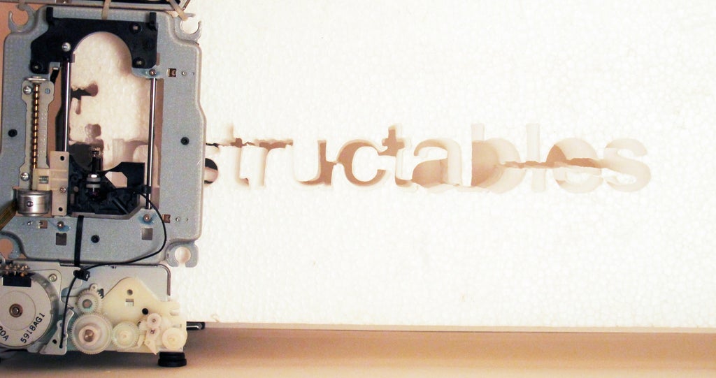
A mini CNC foam cutter made from a compact photo printer, a computer DVD drive and a hair drier.
Read more here: https://www.instructables.com/Mini-CNC-Foam-Cutter/
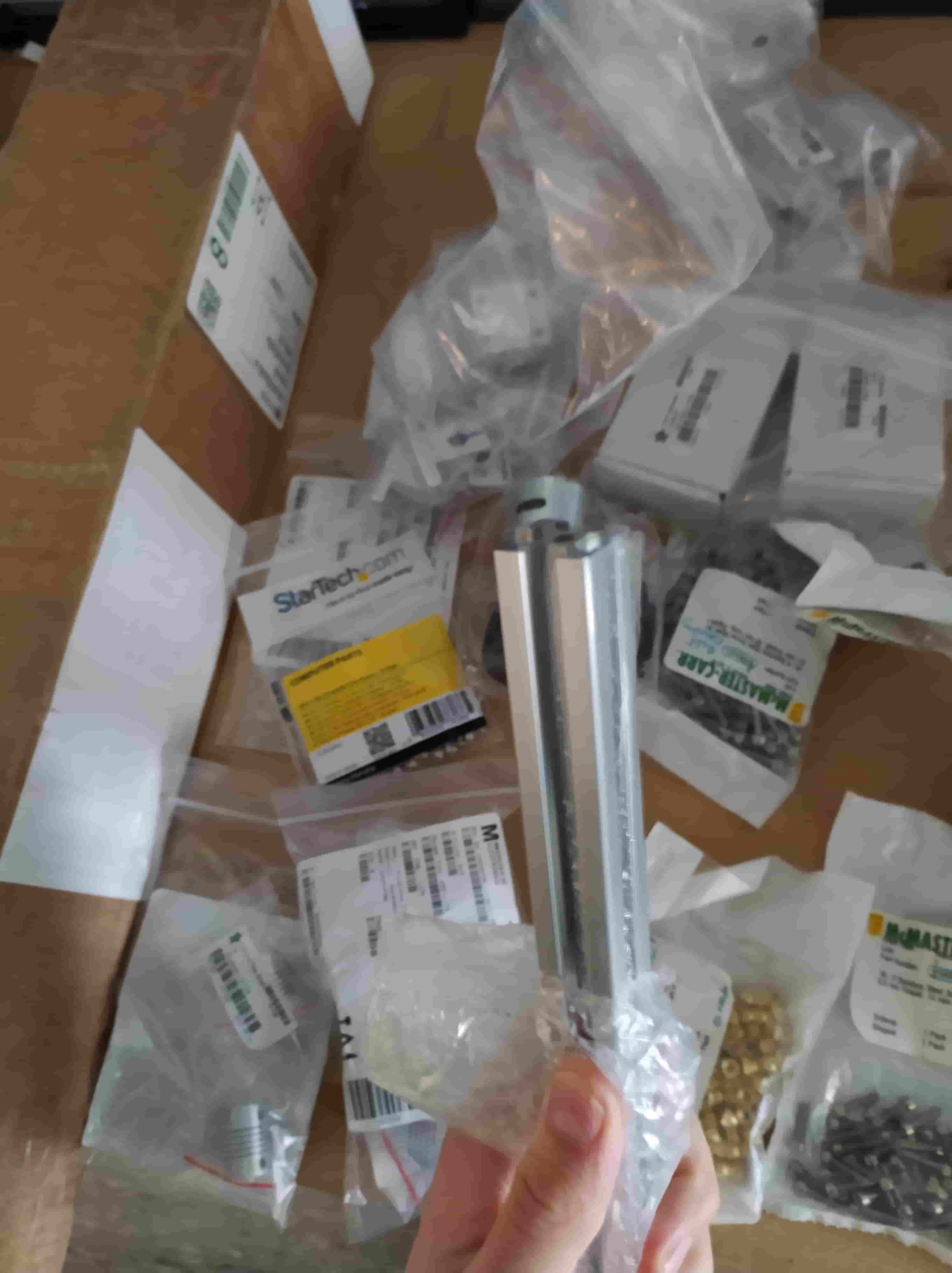
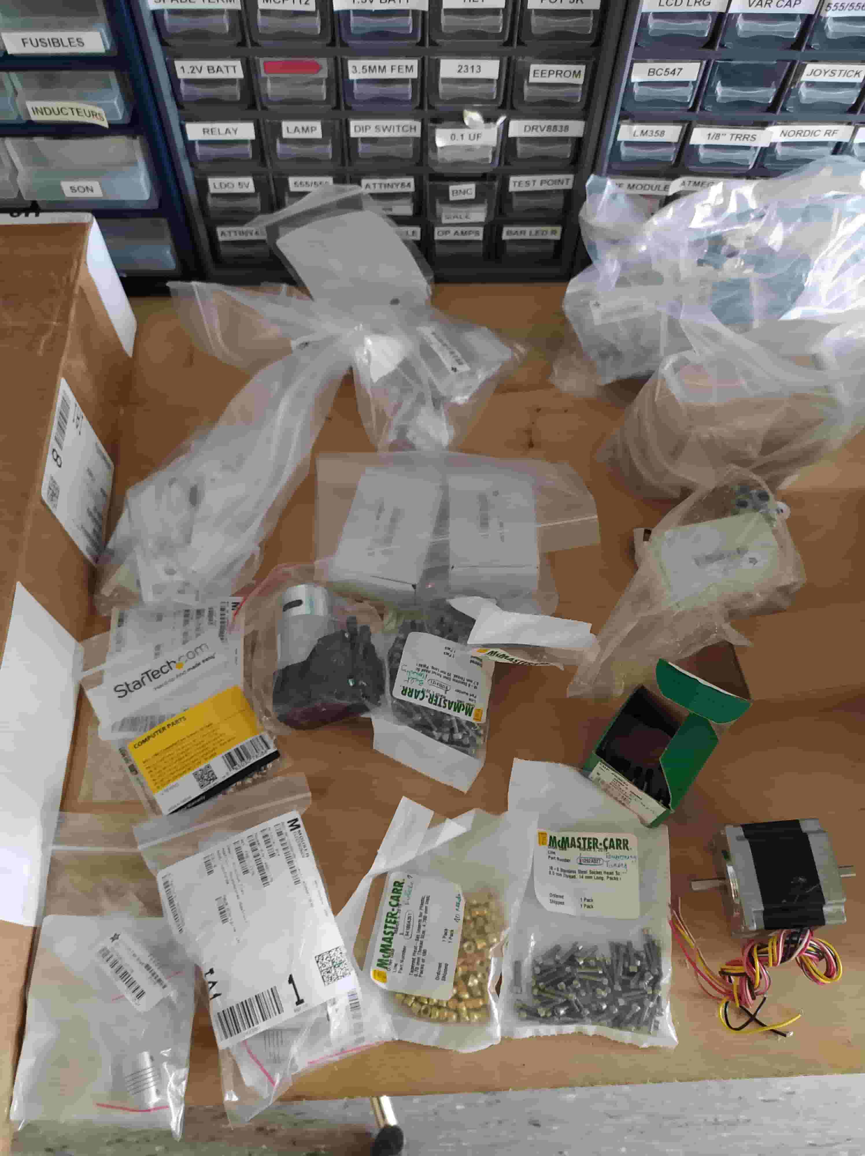
Gathering Materials
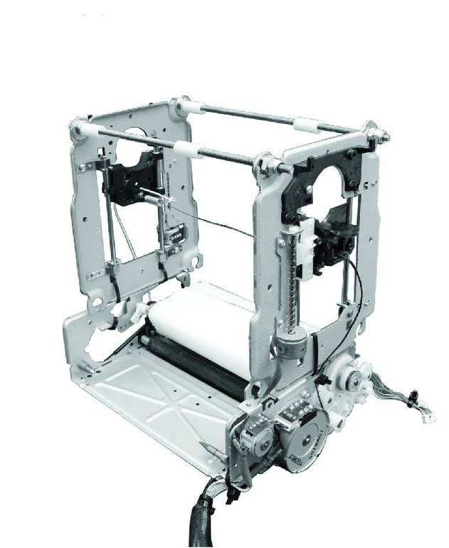
Our first step was to gather all of the mechanical components we had in the lab on a table.
We had the carcass of an old Ultimaker 2, extruded aluminum, geared stepper motors, assorted hardware, linear rails with sliding cams, pillow blocks, pullies, toothed belt…
Overall design
We decided collectively on a pick and place machine, but set the realistic goal of having an X-Y plotter ready for next class.
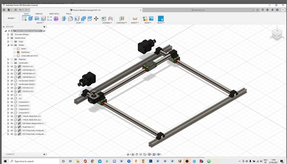
The design is centered on making 3D printed parts which connect three of these rails from adafruit (https://www.adafruit.com/product/1866) and hold in position some NEMA steppers and gear belt.
This image was made by Ambroise de Vries (http://fabacademy.org/2020/labs/digiscope/students/ambroise-devries/):
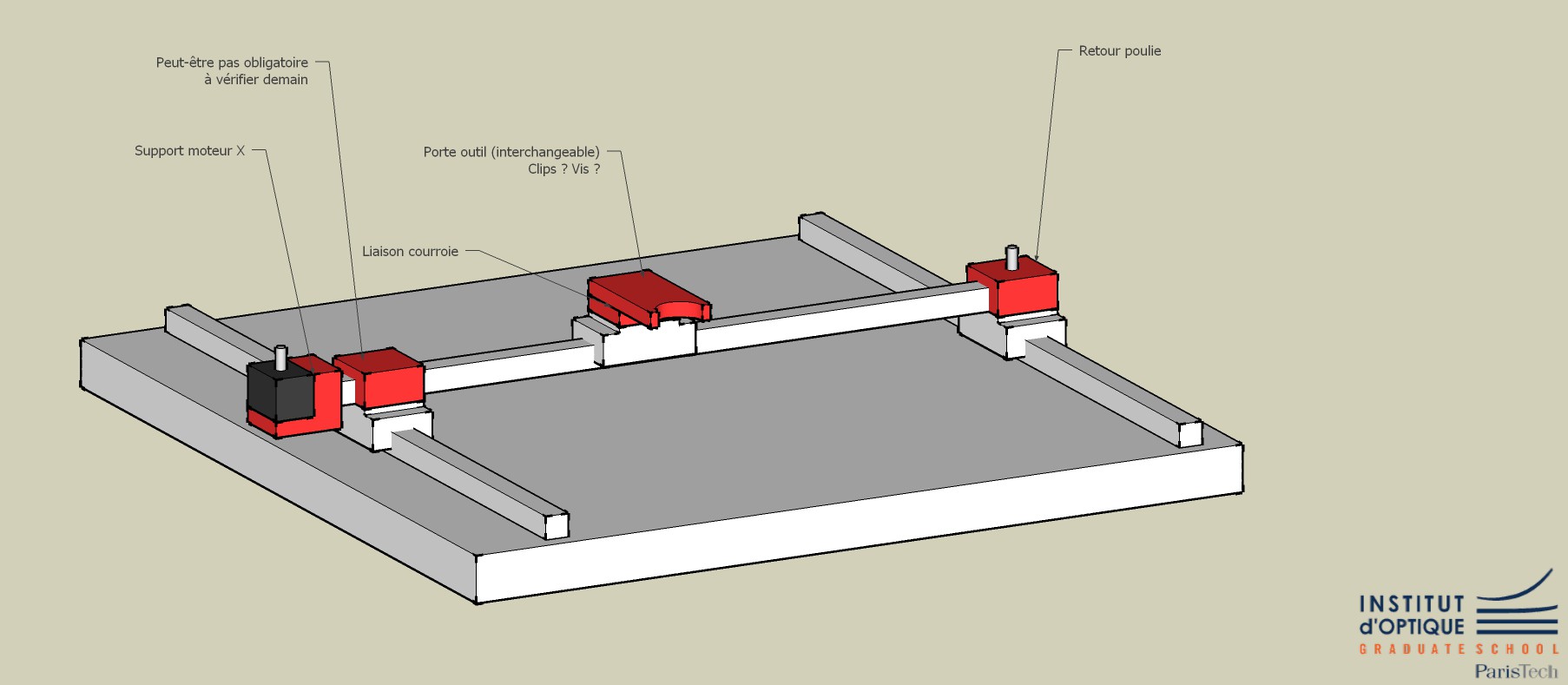
This image was made by Ambroise de Vries (http://fabacademy.org/2020/labs/digiscope/students/ambroise-devries/):
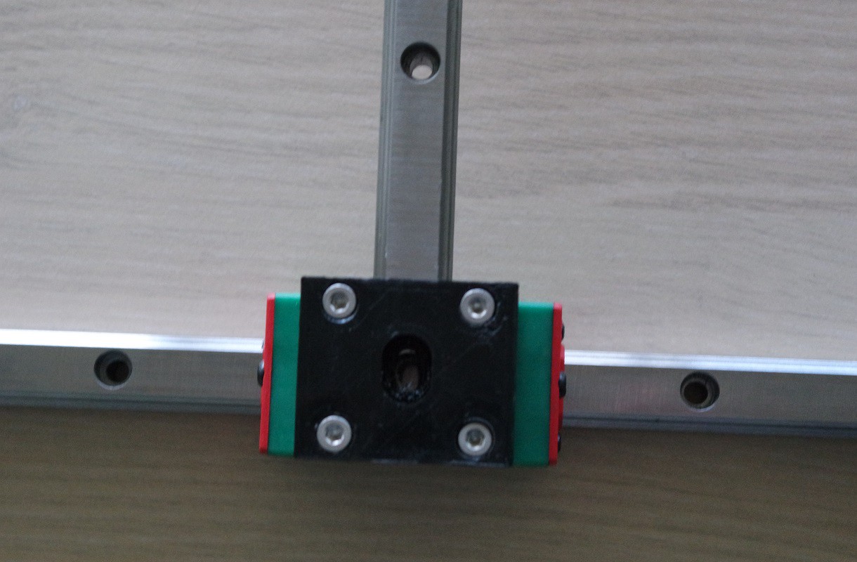
This image was made by Selena Pere (http://fabacademy.org/2021/labs/digiscope/students/selena-pere/):
Software and Electronics
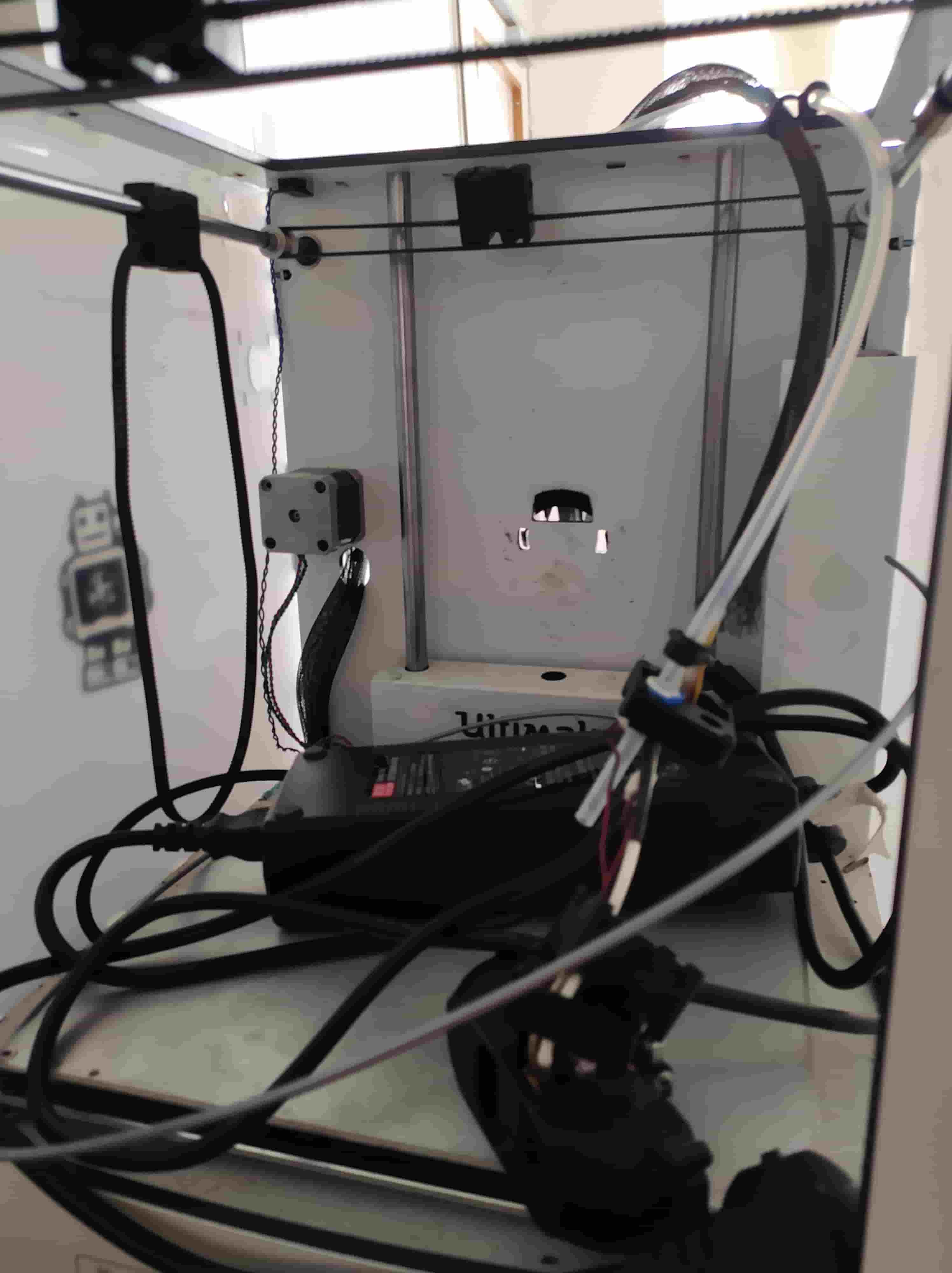
We are using the Tiny G controller. Last year for our foam cutter we used the same board along with Chilipepper.
Here are some photos of the setup we had last year that we are reproducing this year:
Here are the motor connections on the TinyG:
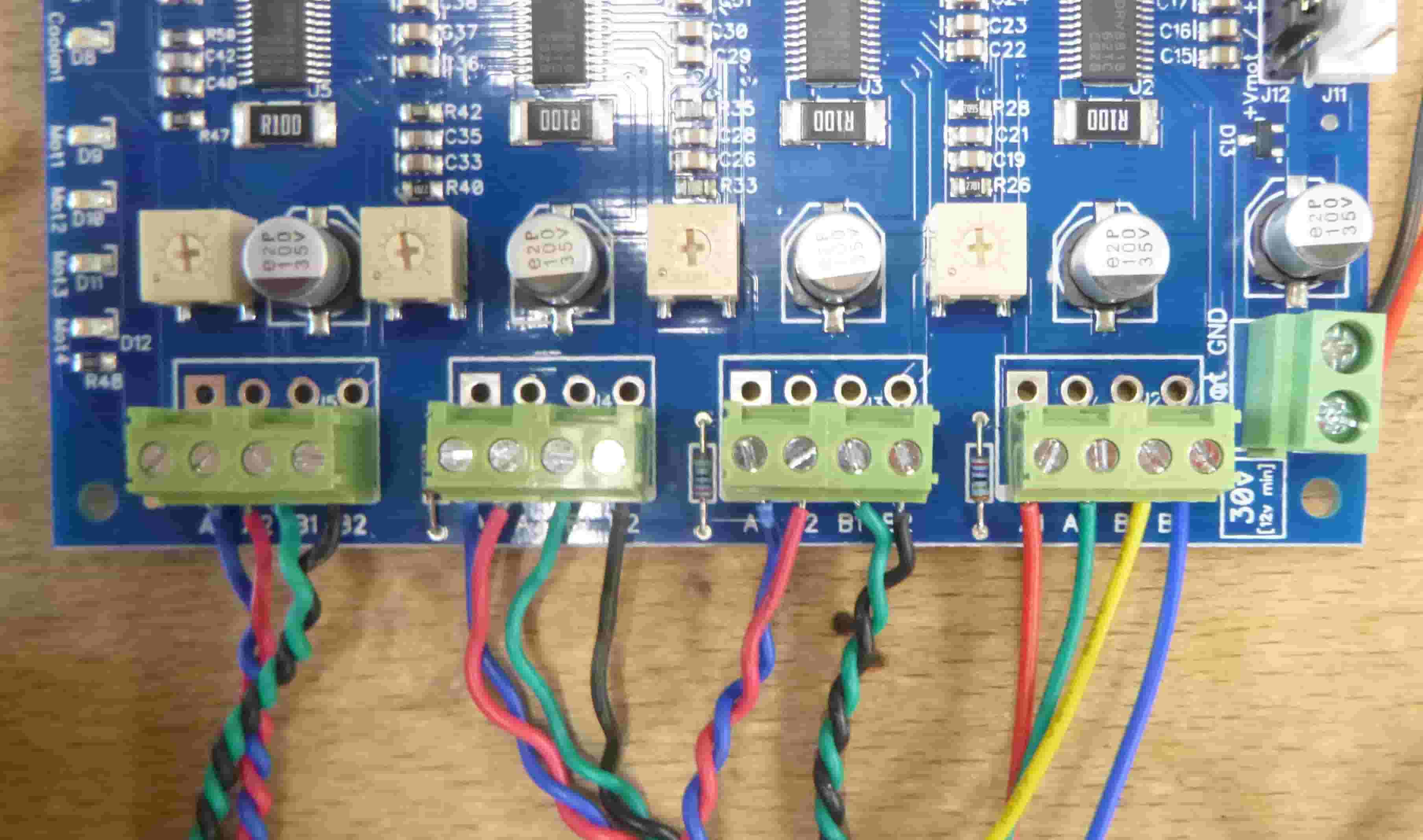
To identify the two motor coils there exist several methods, I use a multimeter to measure the resistance until I find two coils that are connected and have the same resistance. There are also slots for the limit switches, power, and USB communication.
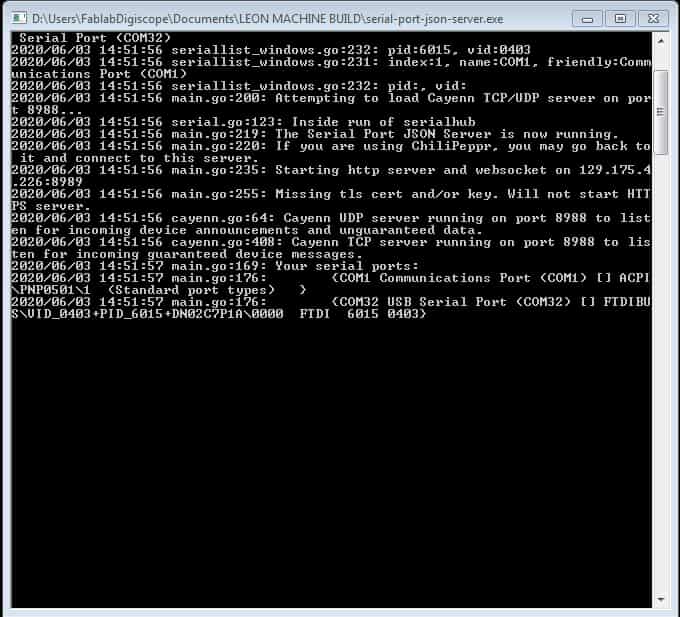
To run chillipeppr you must first download a JSON server to allow the website to communicate directly with the USB ports.
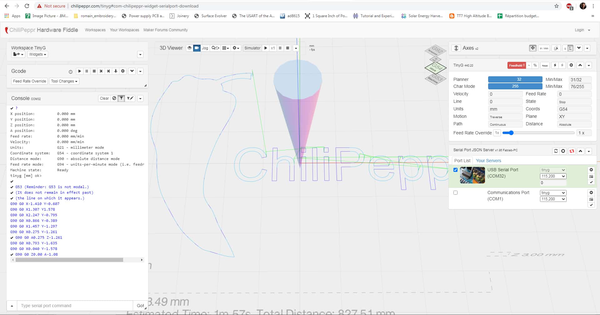
Here are some commands for configuration that served me well last year:
Chilipeppr Configuration (https://github.com/synthetos/TinyG/wiki/TinyG-Configuration-for-Firmware-Version-0.97):
To change the Motor – Axis assignment in Chilipeppr:
$1ma=0 Maps motor 1 to the X axis $2ma=1 Maps motor 2 to the Y axis $3ma=0 Maps motor 3 to the X axis $4ma=1 Maps motor 4 to the Y axis
To assign the same travel per revolution for axis 4 as for the other 3 axes: $4TR 1.25 To swap polarity of a motor: $1PO 0 = Normal motor polarity 1 = Invert motor polarity To set X axis minimum and maximum end stop limit switches (the switches connect GND to XMIN or XMAX on the Tiny G).
$XSN 3 and $XSX 3
To change the distance for every movement of 1mm:
$1tr VALUE
To change max feedrate in X:
$xfr
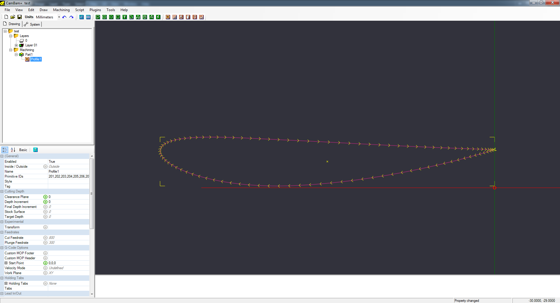
Generating the GCode
To actually generate the GCode I used CAM BAM with a form I drew in Rhino:
Before this I just test some GCode commands to make sure the configuration is correct. My method is to tell Chilipeppr to move 1 unit and then measure the actual distance covered and then scale the numbers in the config accordingly.
Gcode is super simple. For example to have the machien move one unit I type: G0 X 1.0 (to test the X-axis). Because G code is absolute by default, if I want to get it to move again I need to send some other coordinate like G0 X 2.0 .
My contribution: The mini Z-axis ?
I’m adapting this design which already has stepper motor control:
The main issue I can see at the moment is how to power the motor using the same board that controls the other (much beefier) motors. I could turn the current super low but this motor wants to run at 5V, not at 12V. One solution is to have another arduino that just listens for up and down commands from the board and does this itself. This would be a completely seperate electrical system.
I’m still thinking about how to solve this problem…
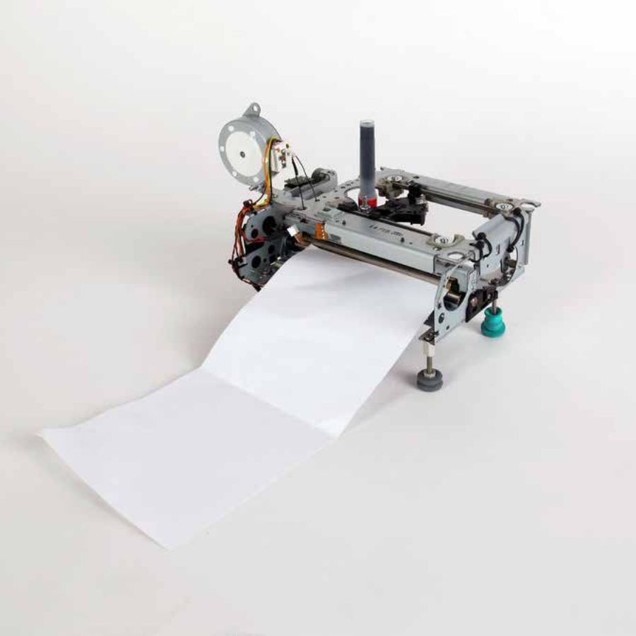
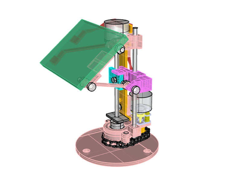
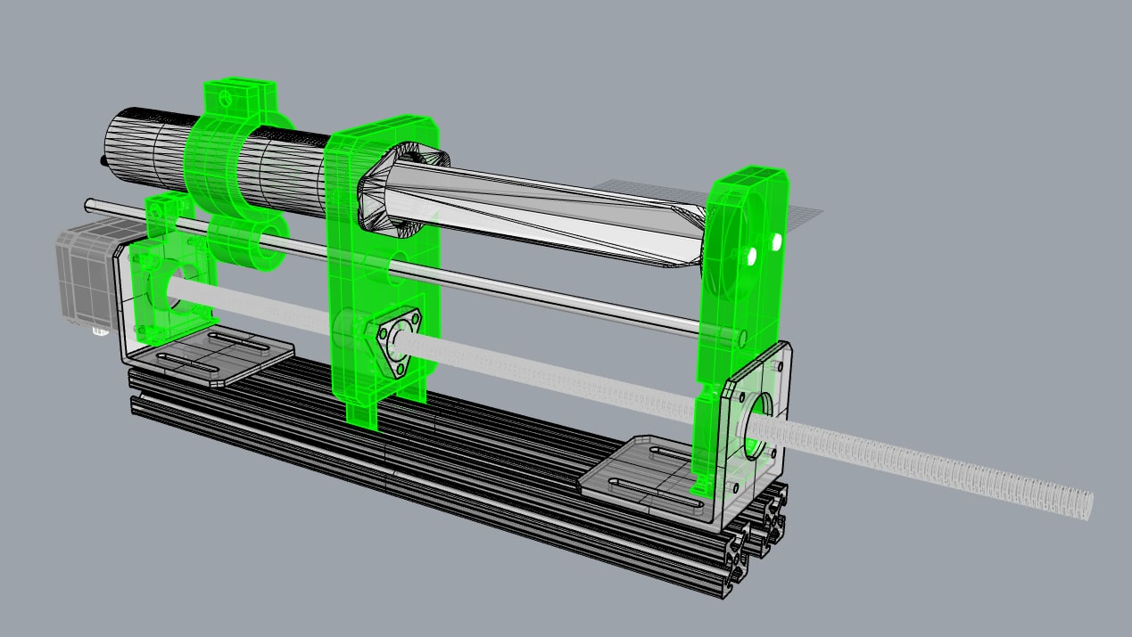
My contribution: A suction gripper !
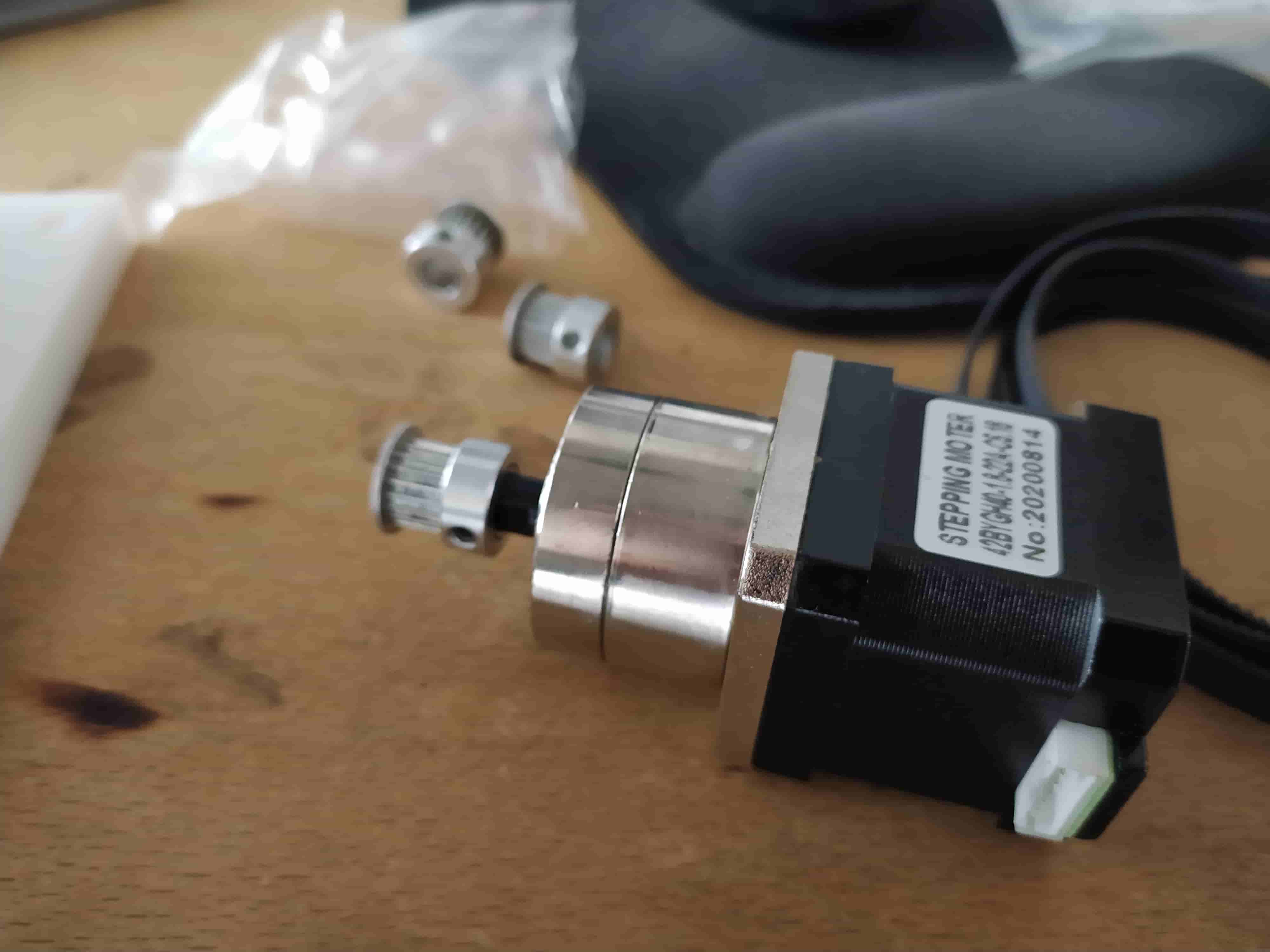
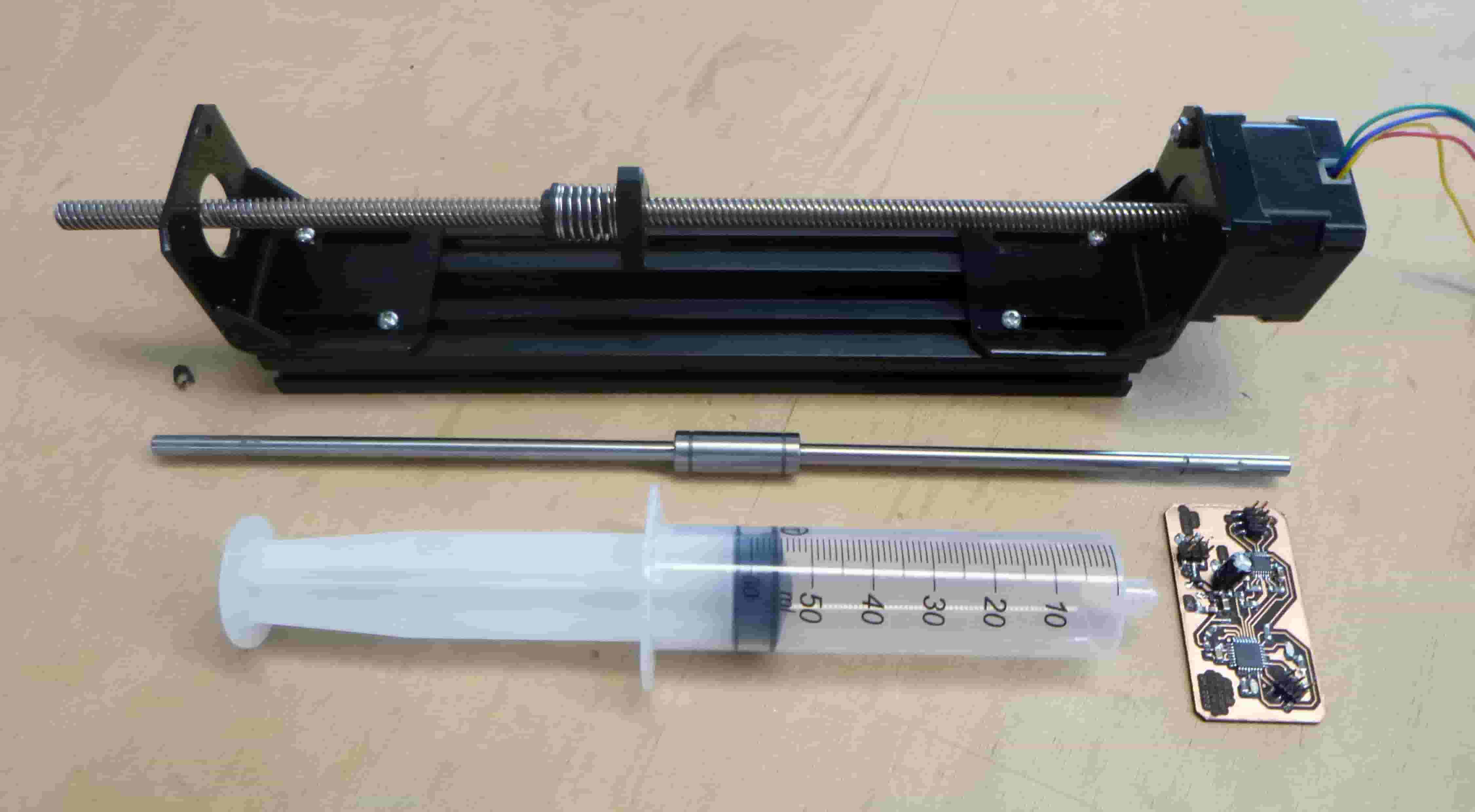
This is the syringe pumping prototype I developed to work as a suction gripper along with the CNC machine. It uses 8020 aluminum extrusions, a NEMA stepper with built in threaded rod, NEMA motor brackets, and linear bearings. The rest is 3D printed and uses M3 and M4 screws.
I have documented all the files here:
https://github.com/merlinmarrs/FabVenti
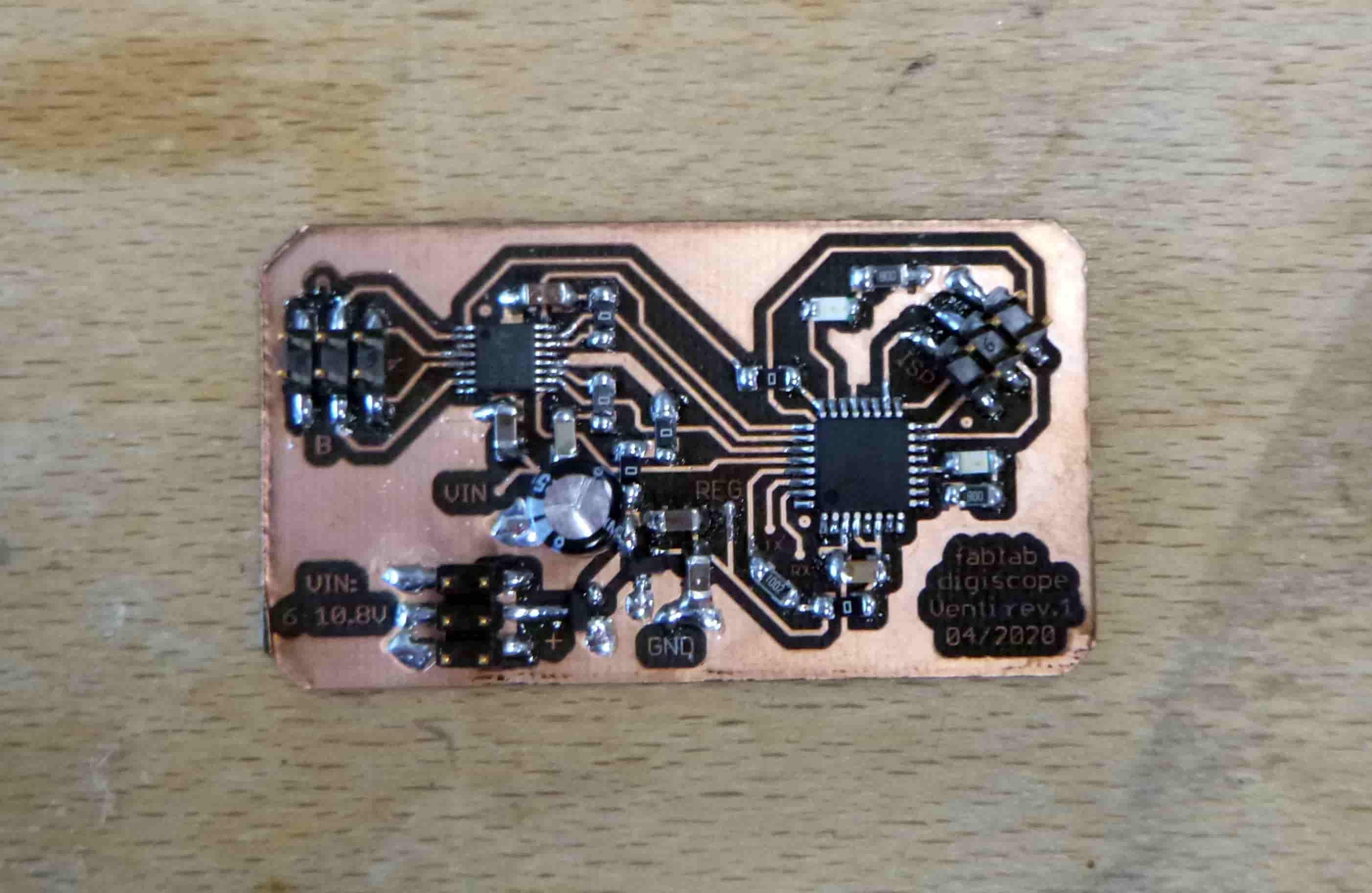
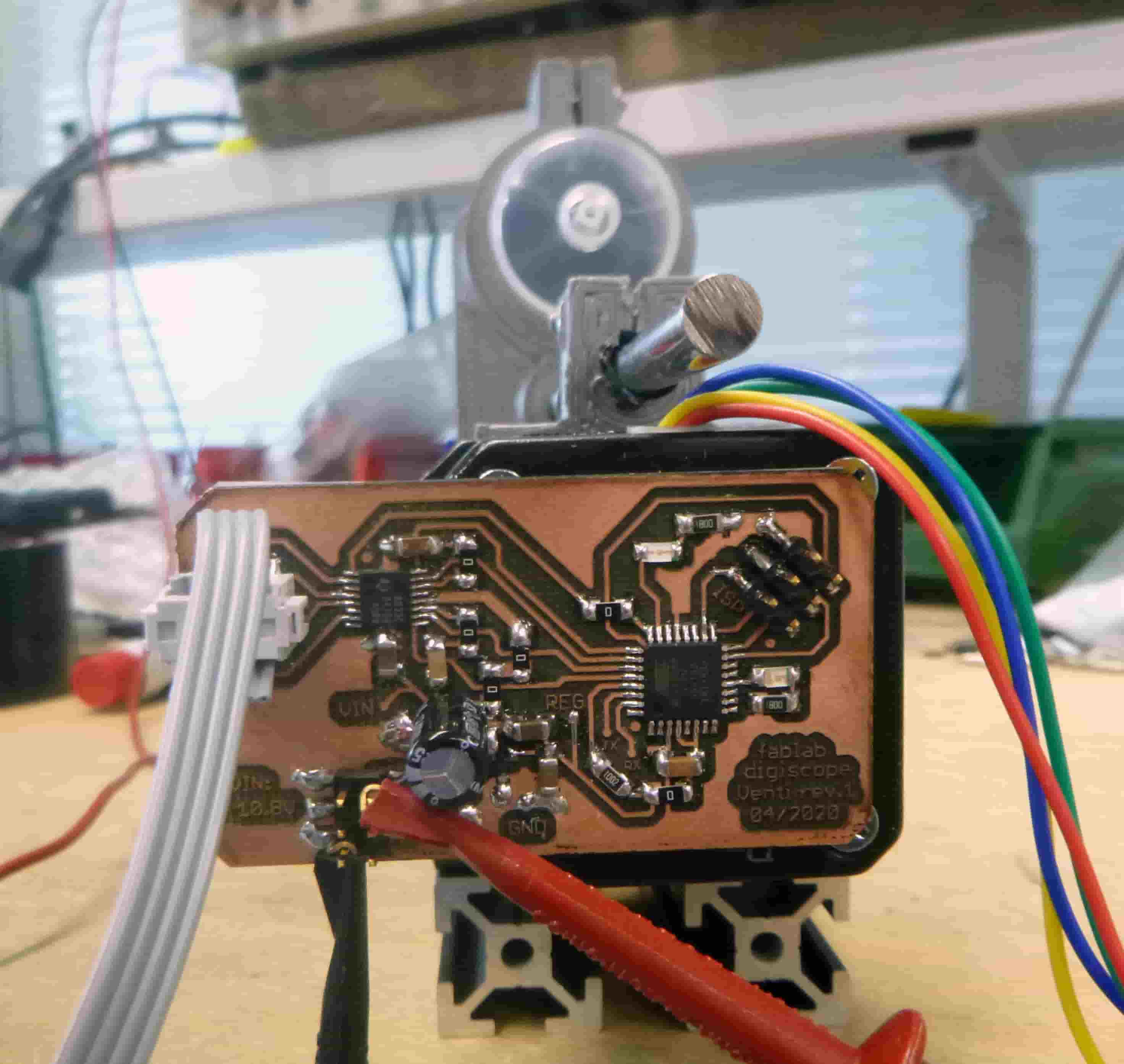
Here’s how the electronics comes together :
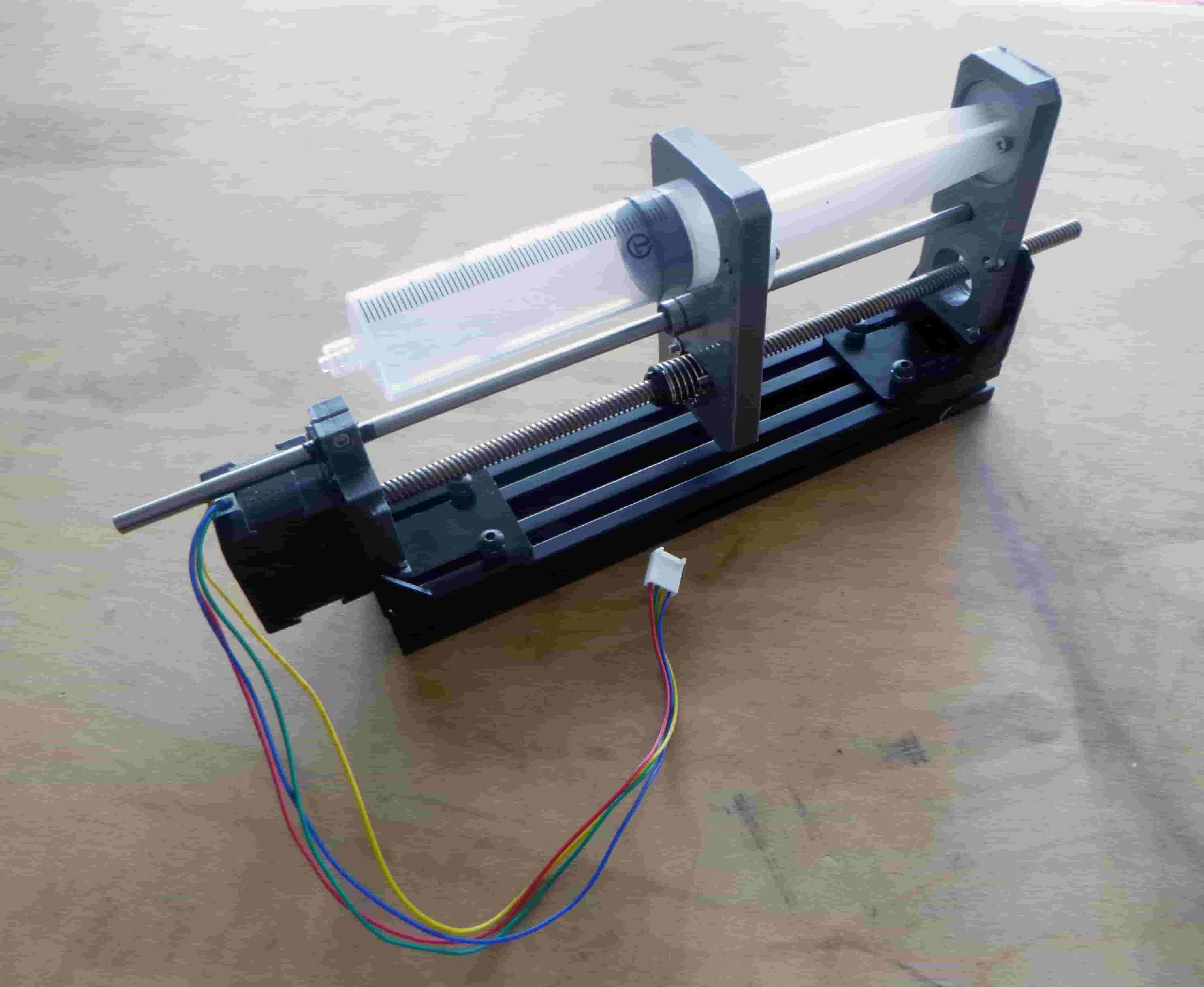
After some experiments I came up with this simple design to improve performance with an added guide rail for stability:
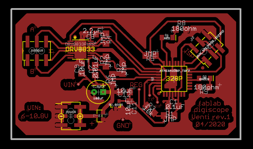
Here is the finished driver. I tried to design it better than usual - respecting the DDR8833 datasheet suggestions as best I could and indicating the relevant pins better than usual.
Here is the file in eagle. It has reverse polarity protection too ! :
Here it is installed on the back of the stepper motor. I was afraid that noise from the stepper motor might cause problems for the circuit but so far no troubles.
Here are the main parts of the pump :
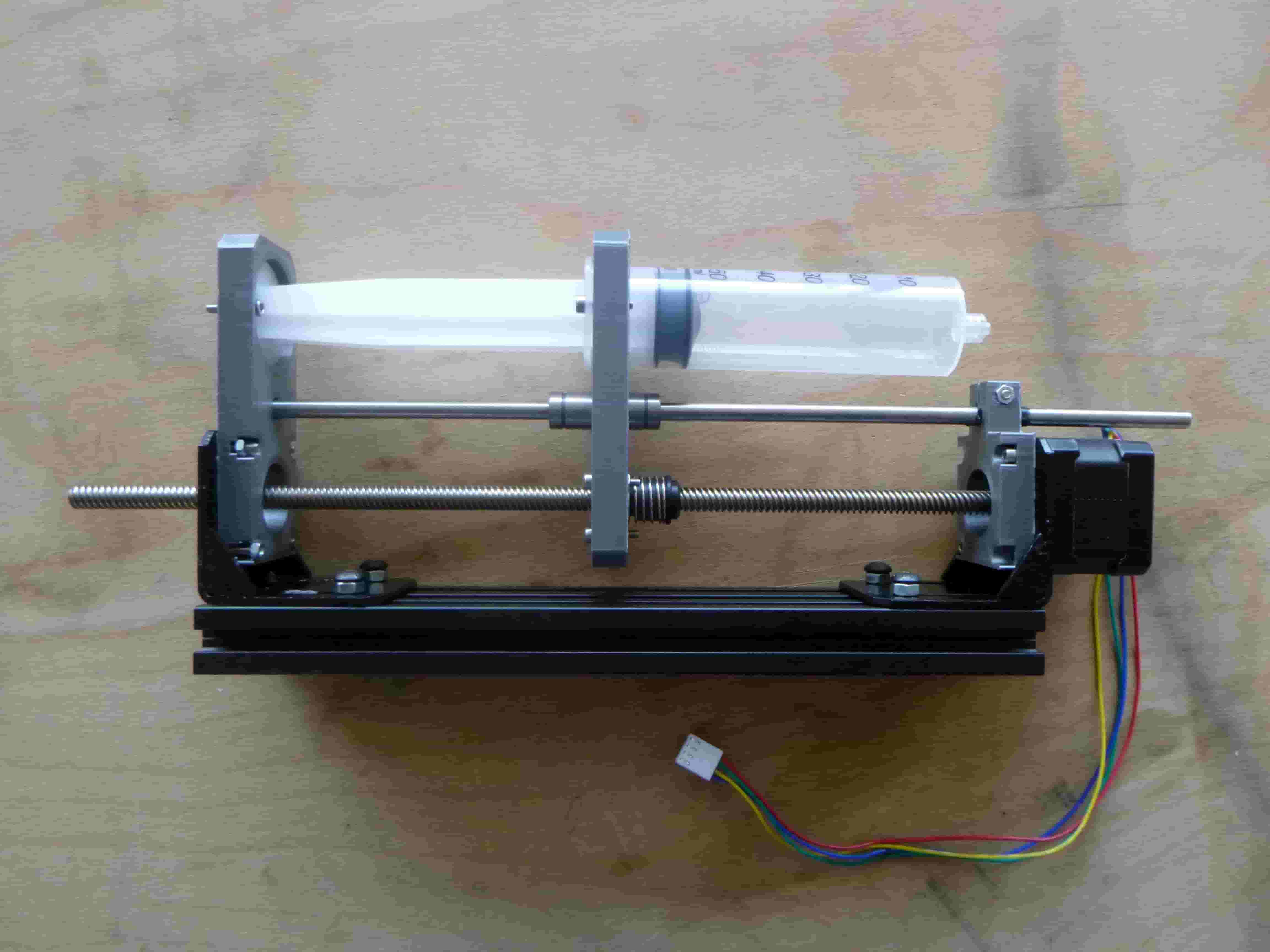
And here it is essembled in side view:
And in perspective in all its glory !:
Here is the C code to test the microchip after soldering:
// Fablab Digiscope //
// Venti Rev.1 Blink Test Code //
// 04/2020 //

// Target: Atmega 328P //

#define F_CPU 8000000 // I also disable the CLKDIV8 fuse //

#include <avr/io.h>

#include <util/delay.h> // because I'm using _delay_ms() //

int main(void)
{
 DDRC = 0b11111111; // All port C pins set to output
 DDRB = 0b11111111; // All port B pins set to output

    while (1) // while value inside the brackets is non-zero,
    {
        PORTC = 0b11111111; // All port C pins HIGH
    PORTB = 0b00000000; // All port B pins LOW
        _delay_ms(1000); //1000ms = 1 second


        PORTC = 0b00000000; // All port C pins LOW
    PORTB = 0b11111111; // All port B pins HIGH
        _delay_ms(1000);

    }
    return (0);
}
And here is the Arduino sketch to actually turn the motor :
#include <Stepper.h>

// change this to the number of steps on your motor
#define STEPS 200

// create an instance of the stepper class, specifying
// the number of steps of the motor and the pins it's
// attached to
Stepper stepper(STEPS, A2, A3, A5, A4);

#define RED A0 // RED LED
#define GREEN 8 // GREEN LED

#define SLEEP A1 // by default off, connect to high to activate

void setup()
{
  pinMode(SLEEP,OUTPUT);

  pinMode(RED,OUTPUT);
  pinMode(GREEN,OUTPUT);
  // set the speed of the motor to 30 RPMs
  stepper.setSpeed(60);
}

void loop()
{

  digitalWrite(SLEEP,HIGH);

  digitalWrite(RED,HIGH);
  digitalWrite(GREEN,LOW);
  stepper.step(STEPS);

  digitalWrite(RED,LOW);
  digitalWrite(GREEN,HIGH);
  stepper.step(-STEPS);
}
The idea is to 3D print a flexible material which will act as the gripper and be attached via a tube to the CNC suction device like these described on this sparkfun news website https://www.sparkfun.com/news/2586:
Stay Tuned !