1. Principles and practices + Project Management
This week I worked on defining my final project idea and started to getting used to the documentation process.
I first read this tutorial which was helpful: https://docs.gitlab.com/ee/gitlab-basics/
Here is my attempt to get GitLab working locally:
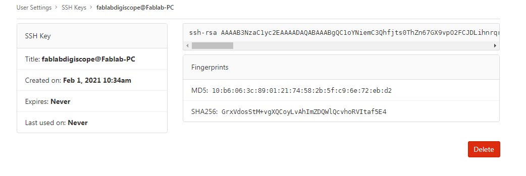
-I downloaded OpenSSH for Windows 7, 64 bit and ran the executable which generates SSH keys. I copied the public key into Gitlab.
-I downloaded my website and put it at the path C:\Users\FablabDigiscope.git . I also turned on invisible files in Windows 7 so that I could see the directory.
-To install MKdocs, I first installed an older version (3.73) of python which works with Windows 7. I then checked that pip was installed and installed Mkdocs double checking that it worked after by checking the version.
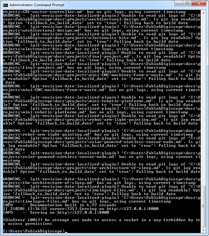
-I ran mkdocs serve and received two errors: 1. the material theme was not installed. 2. revision date location plug-in was not installed.
-I installed the theme and the plug-in with pip and reran mkdocs serve but I get the following error after the documentation is built and put on the server : “WinError 10013 An attempt was made to access a socket in a way forbidden by its access permissions.”
-When I try git commit -m “Updated site” I get an error saying “nothing added to commit but untracked files present”. When I try git init to test that my git repository has been created successfully it generates the files in the correct directory but the same errors are produced.
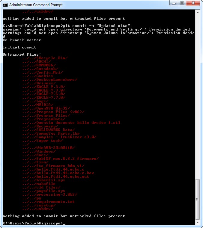
-I configured my user name and email successfully however.
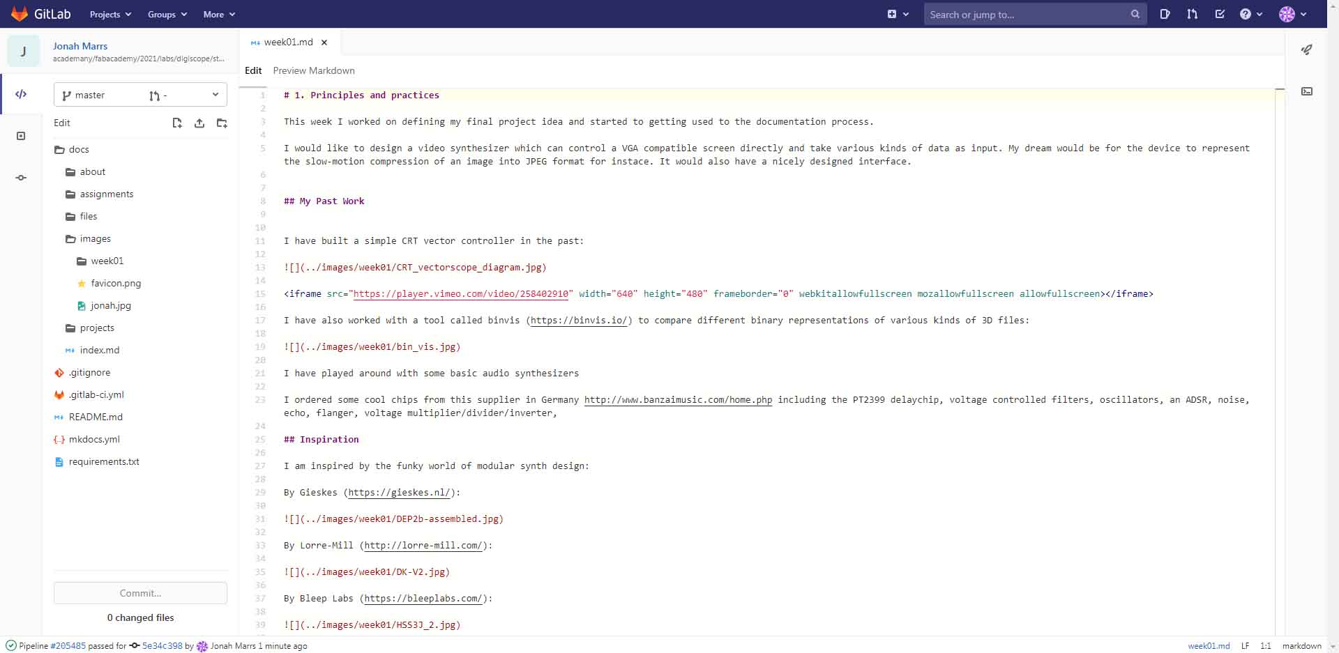
In the meantime I am using the GitLab GUI (without a local copy of the site) to put together this website, modifying the MKdocs file to add some customization - notably moving away from color towards black and white, changing the accent color to red and incorporating this funky retro raster font called VT323.
The main remaining problem is not being able to control the width, height and centering of my images when they are in scroll mode. Otherwise I think I can work committing every so often and refreshing my browser to see the results.
This is not a totally satisfying solution as I cannot modify as much as I would like. However, it does allow me to focus on the content and not get bogged down in the technical details. It therefore satisfies my desire for minimalism.
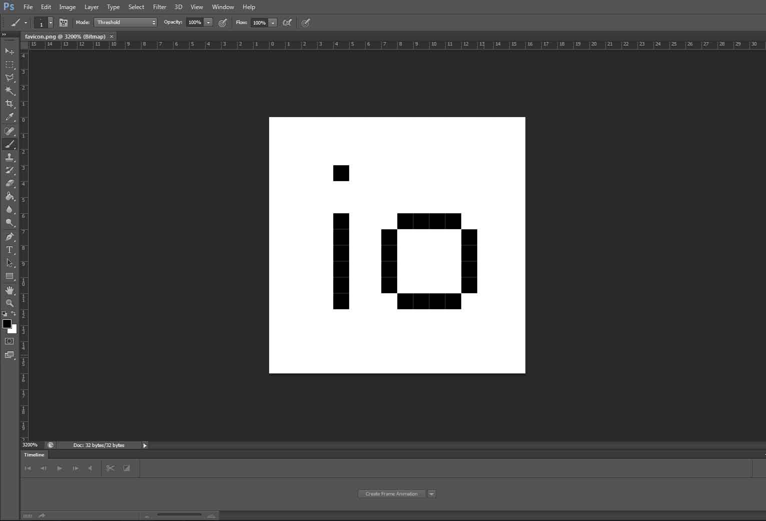
I made my own favicon in Photoshop setting the image to 16x16 pixels. I have been compressing images with Photoshop or simply reusing images already compressed and published on my personal website so far.
For videos, I use Premier Pro for all the editing and compressing to small formats / gifs.
For collaborative tools our lab is using MatterMost chat.
UPDATE
I moved the directory in the command prompt to C:\Users\FablabDigiscope\jonah-marrs and now I can push and pull no problem:
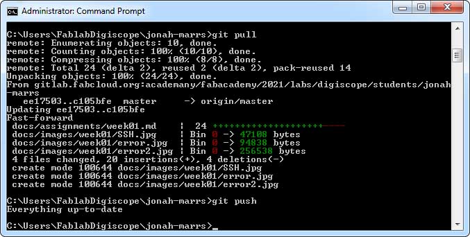
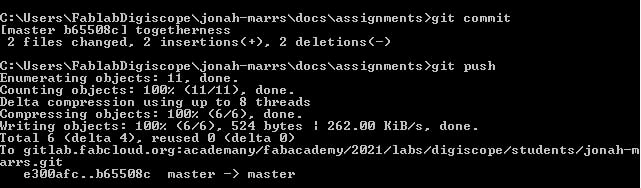
I’m using Notepad ++ to do my text editing and the command prompt to commit and push.
Final Project Ideation
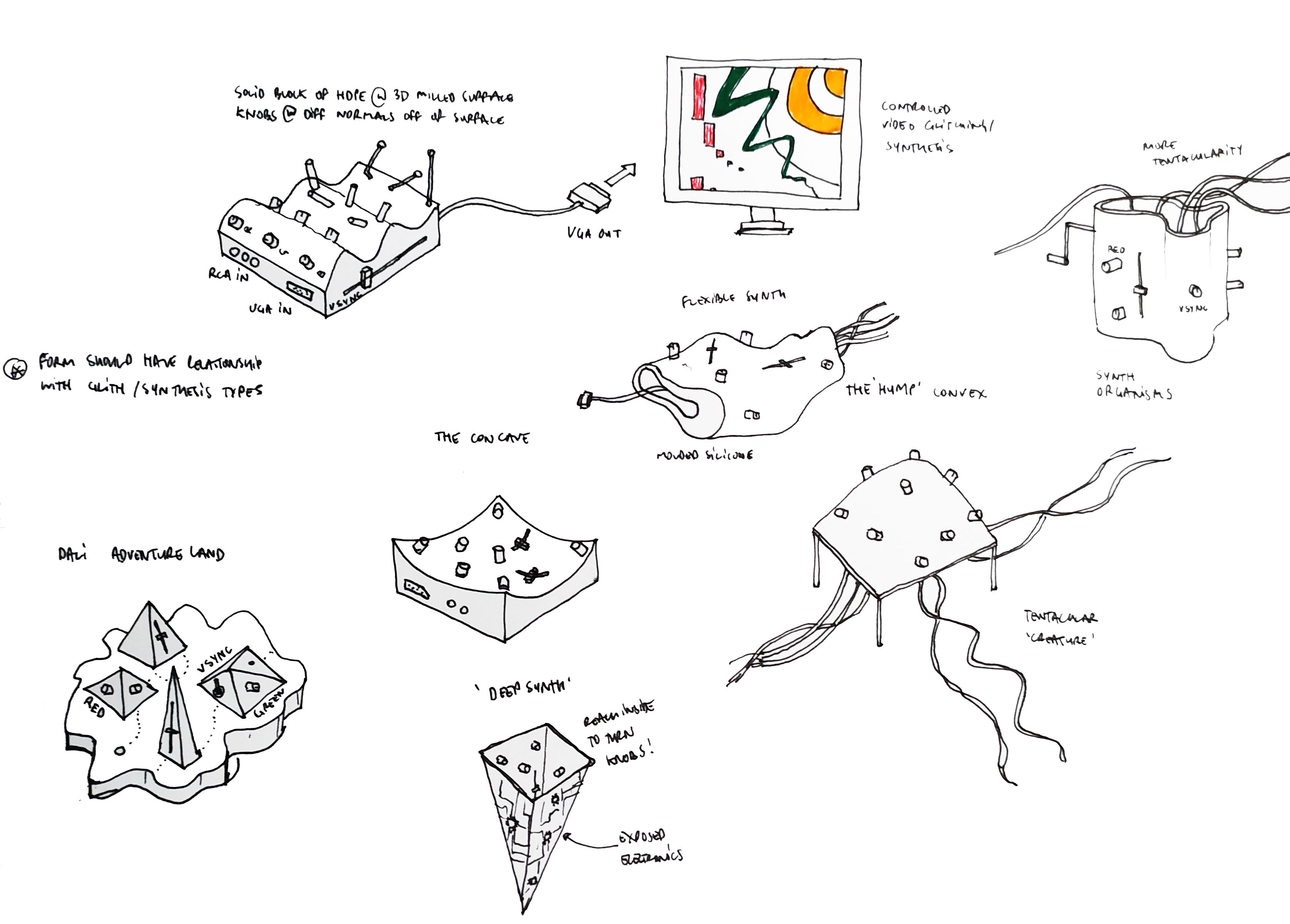
I would like to design a video synthesizer which can control a VGA compatible screen directly and take various kinds of data as input. My dream would be for the device to represent the slow-motion compression of an image into JPEG format for instace. It would also have a nicely designed interface.
My larger interest is to study the technics of computer representation itself. I like the idea of investigating the moment when systems break down to better understand it - like physicists studying particles by looking at their collisions.
Here are some sketches of the final product:
Inspiration
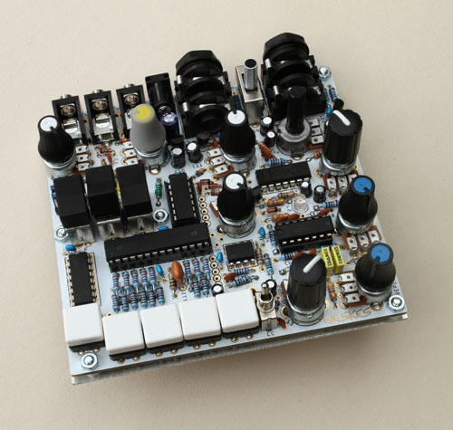
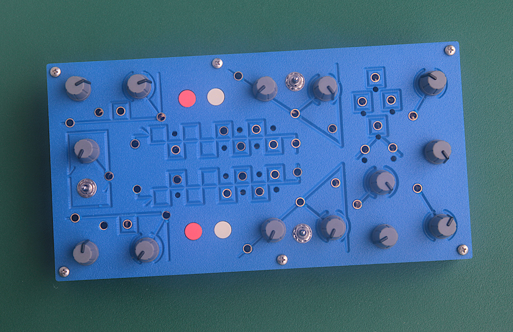
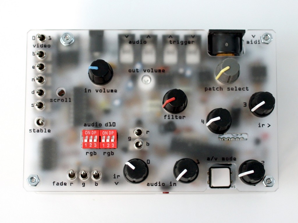
I am inspired by the funky world of modular synth design:
By Gieskes (https://gieskes.nl/):
By Lorre-Mill (http://lorre-mill.com/):
By Bleep Labs (https://bleeplabs.com/):
And early video art pioneers like Nam June Paik:

Ben Eater (a hero of mine!) has a great video on making a VGA controller from logic chips here (https://eater.net/vga):
And a cool mini doc on analog video synths here from Vice Labs
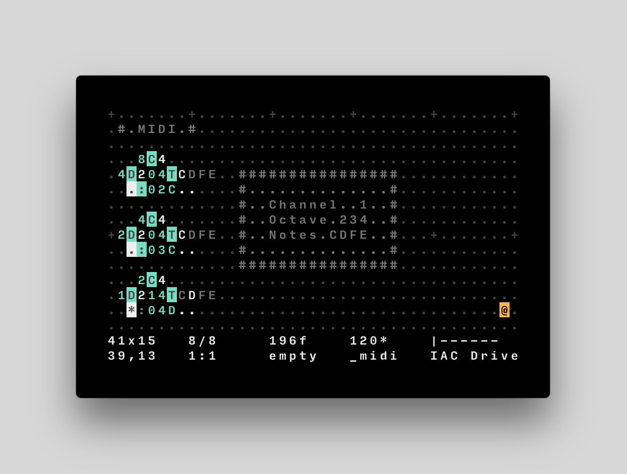
I am inspired by ORCA, a programming language for sound synthesis which is very visual: https://github.com/hundredrabbits/Orca
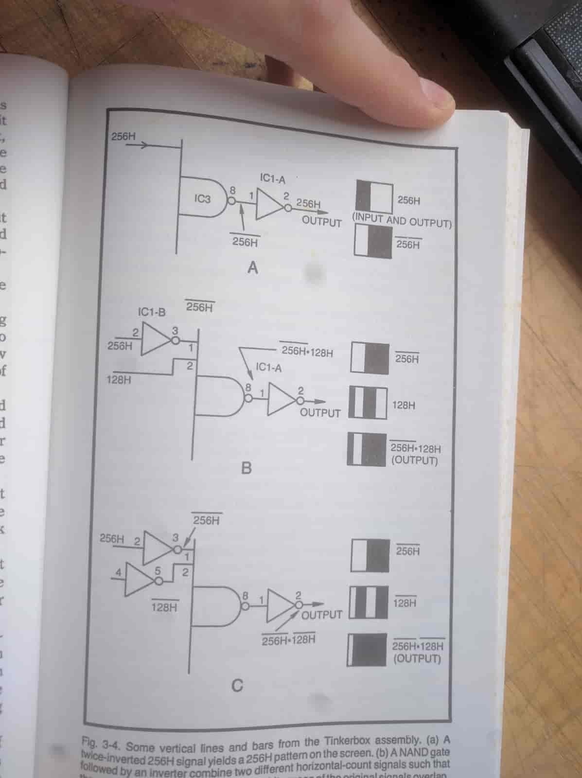
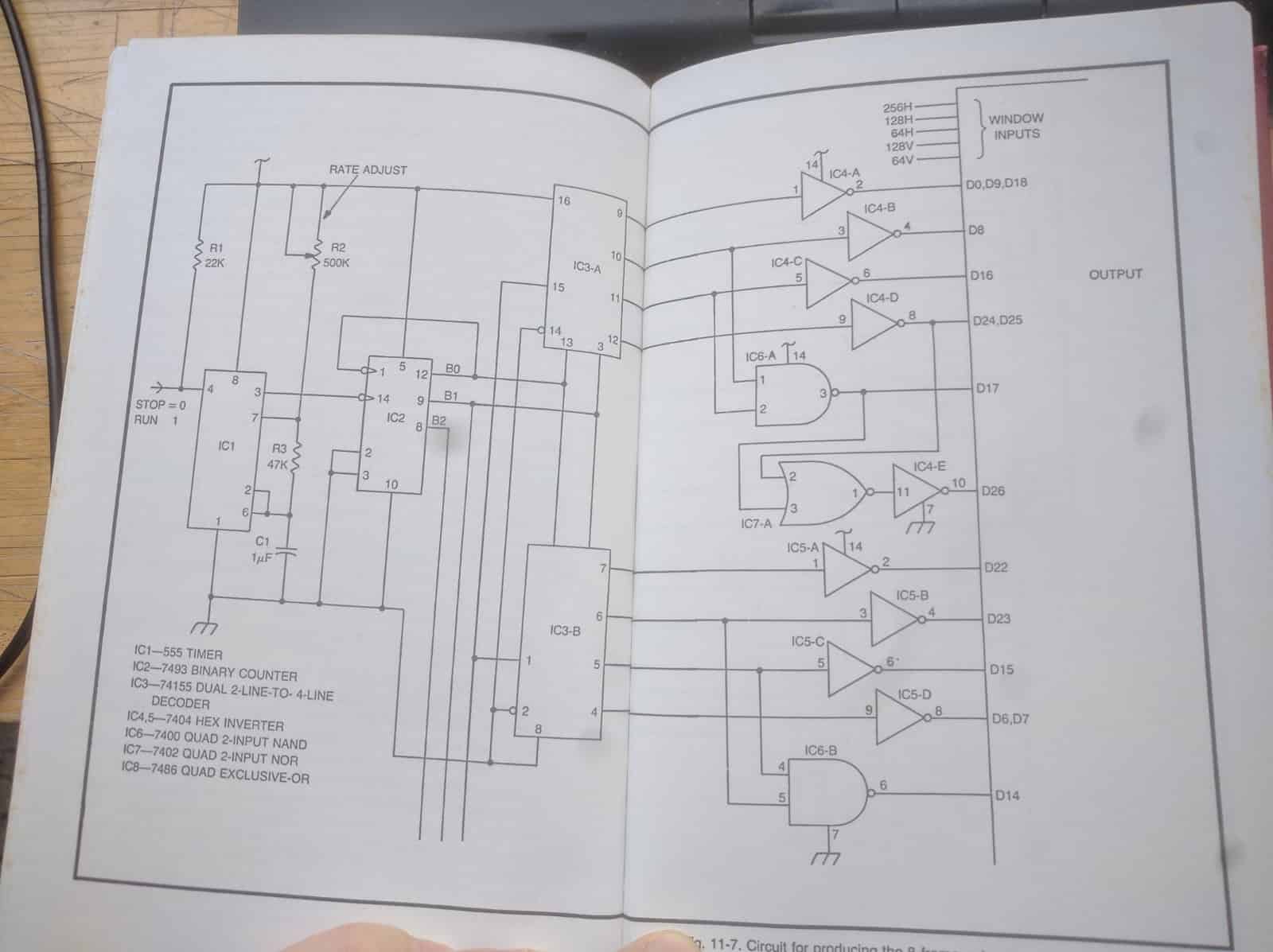
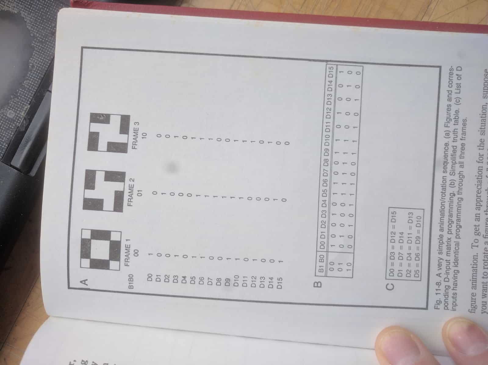
I found a nice book on early computer game graphics with logic chips:
I am inspired by the book Handmade Electronic Music: The art of hardware hacking by Nicolas Collins:
http://loliel.narod.ru/DIY.pdf
As well as one of the original video synths, the Scanimate:
Research: Representing data
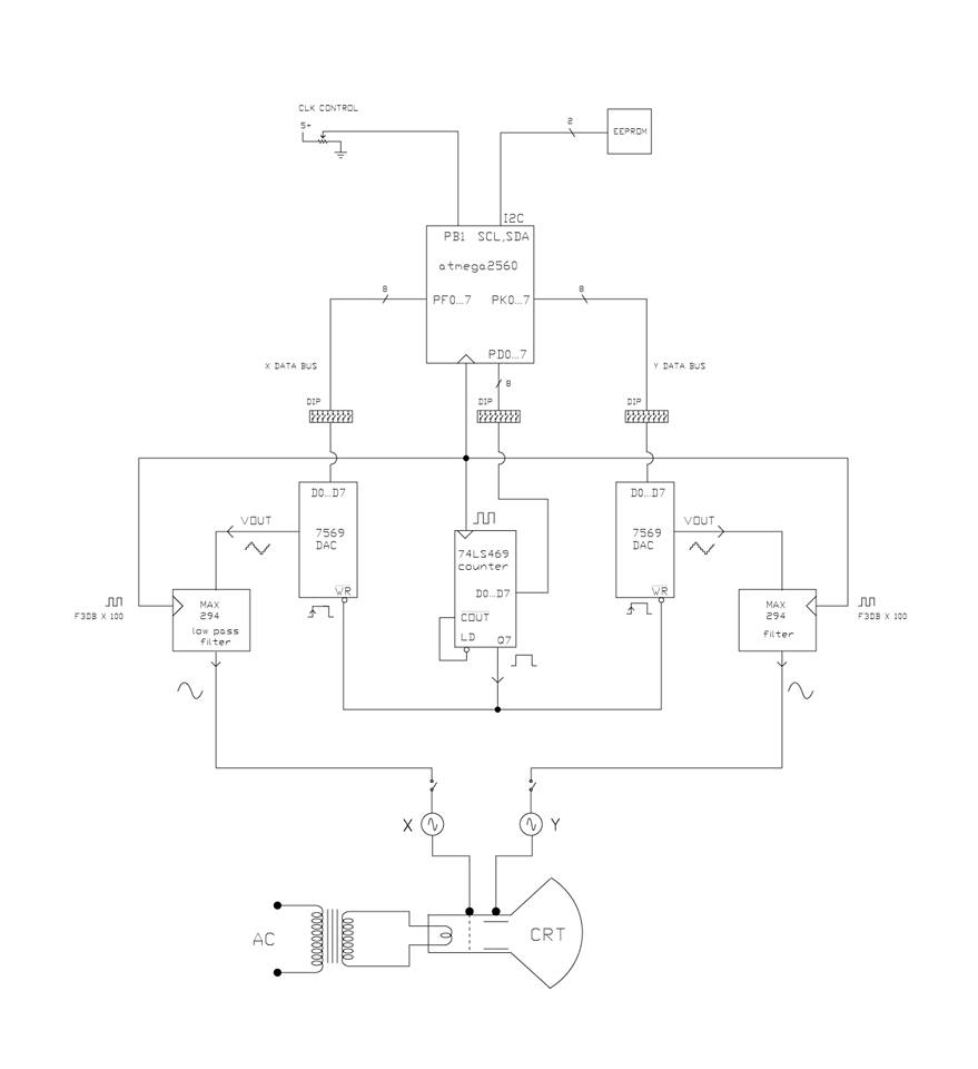
Beyond my other work representing 3D meshing and plotting processes, I have built a simple CRT vector controller in the past:
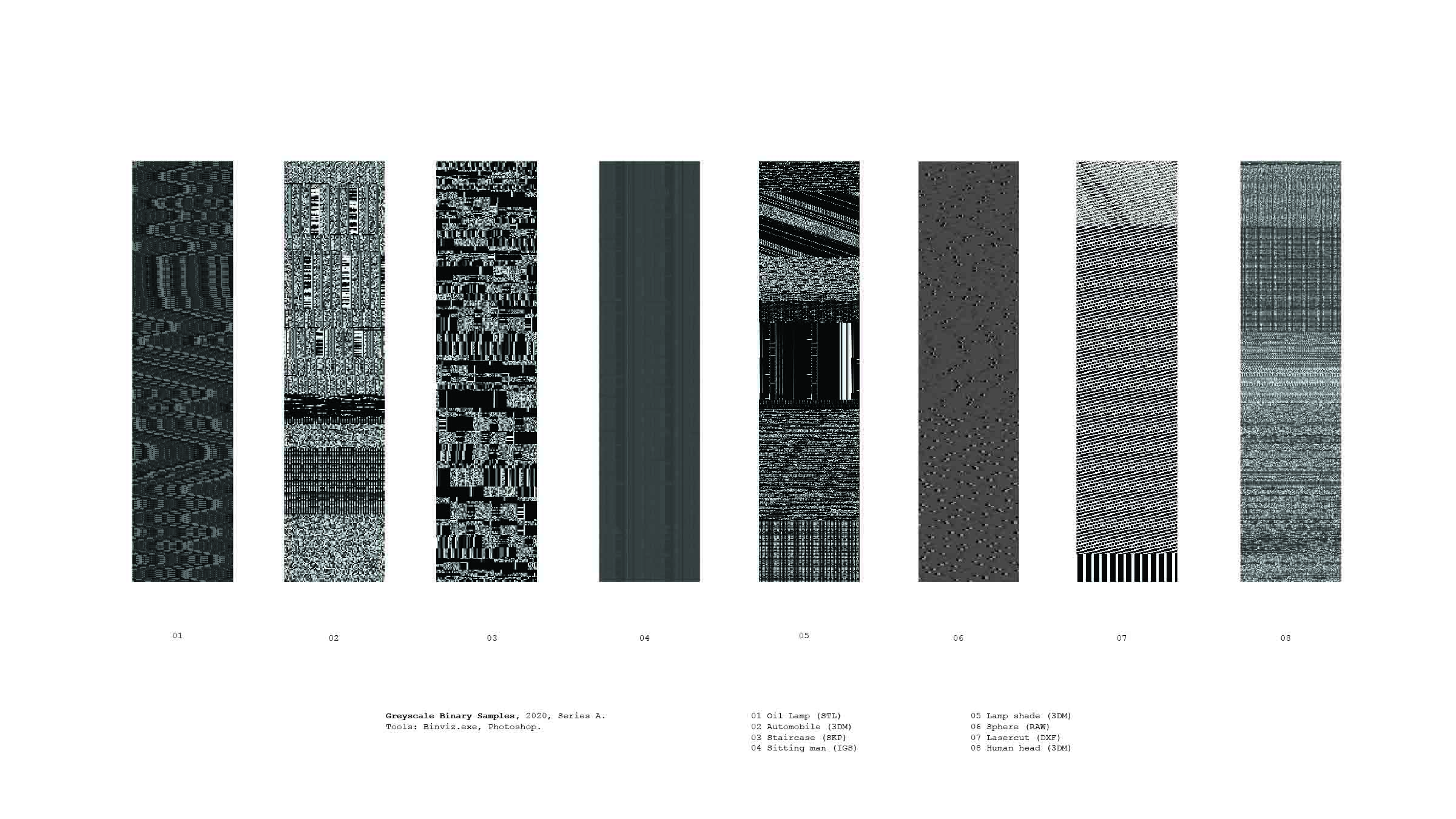
I have also worked with a tool called binvis (https://binvis.io/) to compare different binary representations of various kinds of 3D files:
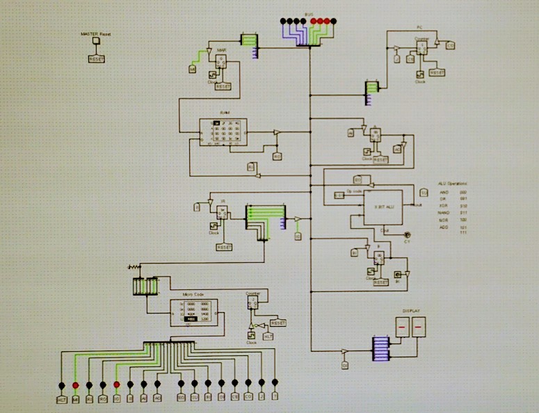
I also have made a simple 8 bit computer in Logisim to better understand low-level data manipulations:
Research: Glitching
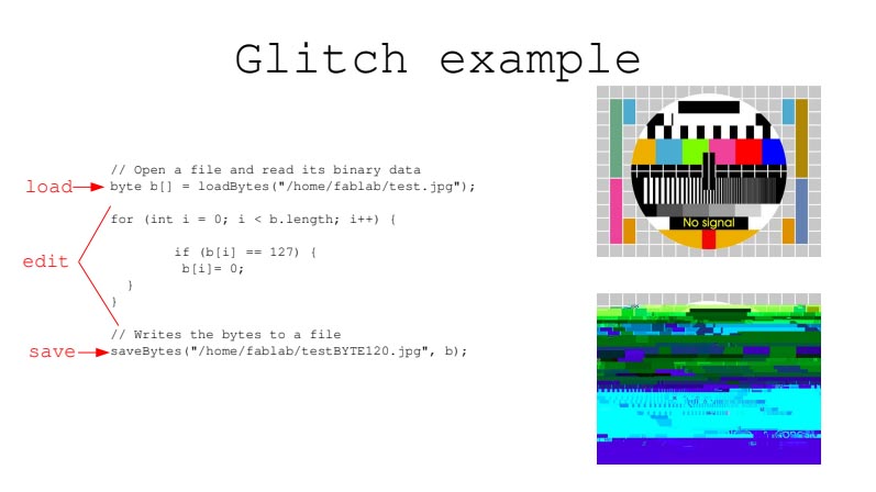
I put together a quick glitching workshop using processing:
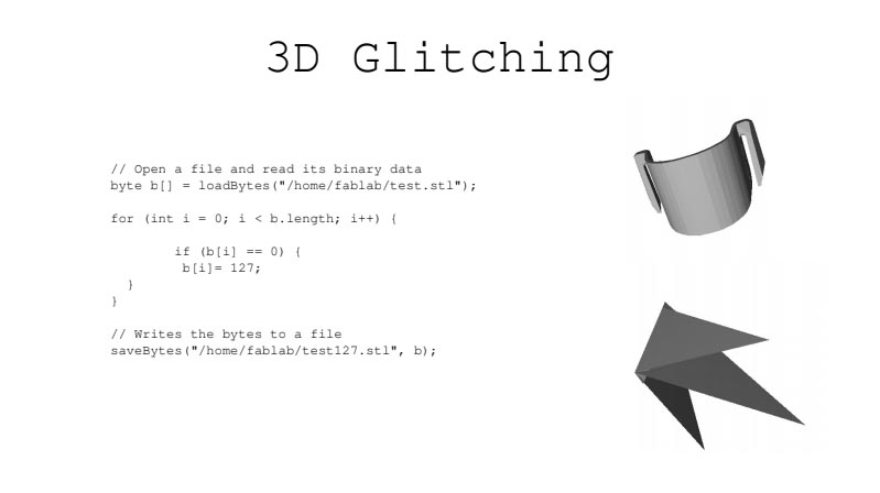
Mark Klink has a great 3D glithing tutorial here: http://www.srcxor.org/blog/3d-glitching/
Research: Modular Audio Synthesis
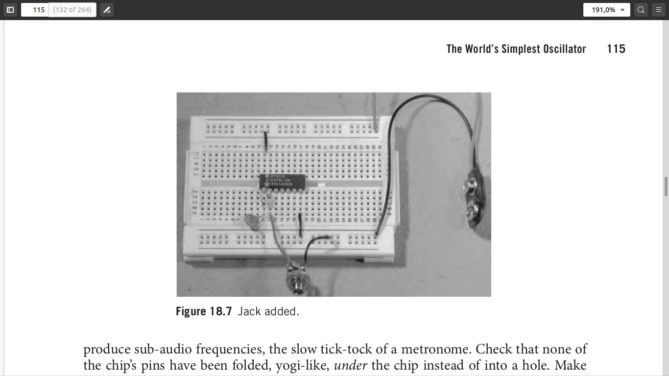
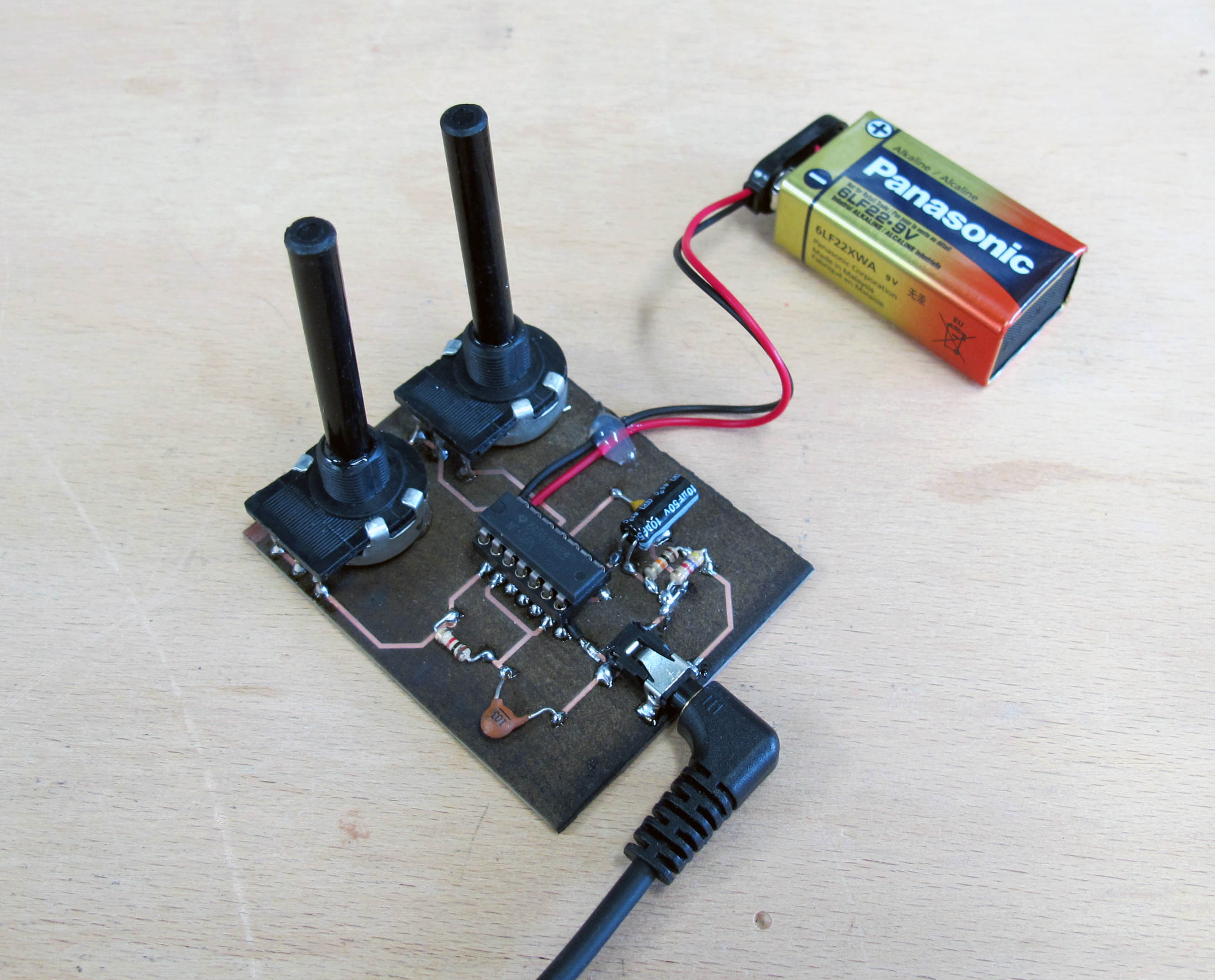
This is a basic pair of cascaded oscillators called the Atari Punk Console (a.k.a. one of Forrest Mims’ Engineer’s Notebook circuits):
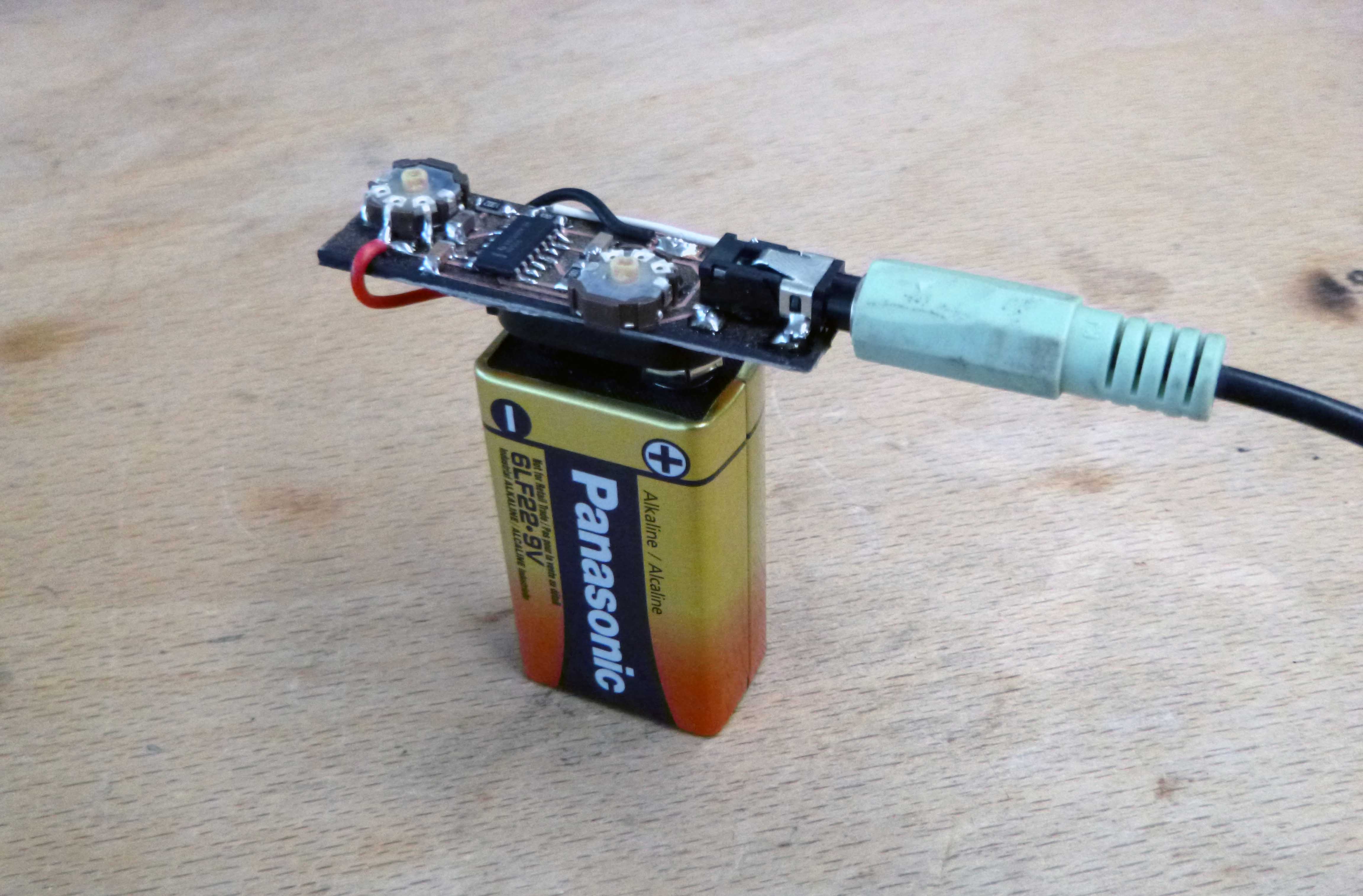
I also made a mini version of the same circuit:
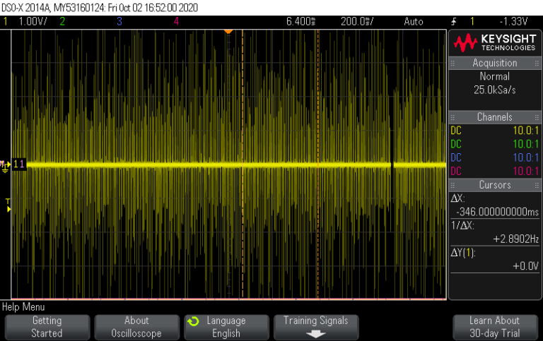
A noise module (using arduino outputing random values and a high pass filter):
A sample and hold module (using two op amps and a MOSFET with a small capacitor):
Here is what the circuit looks like simulated in falstad: https://tinyurl.com/yyf7ofag
an XOR module (XORing a sine wave from a function generator and a square wave from arduino):
Here is what a similar circuit (it has a high pass filter too) looks like simulated in falstad: https://tinyurl.com/y659mcmc
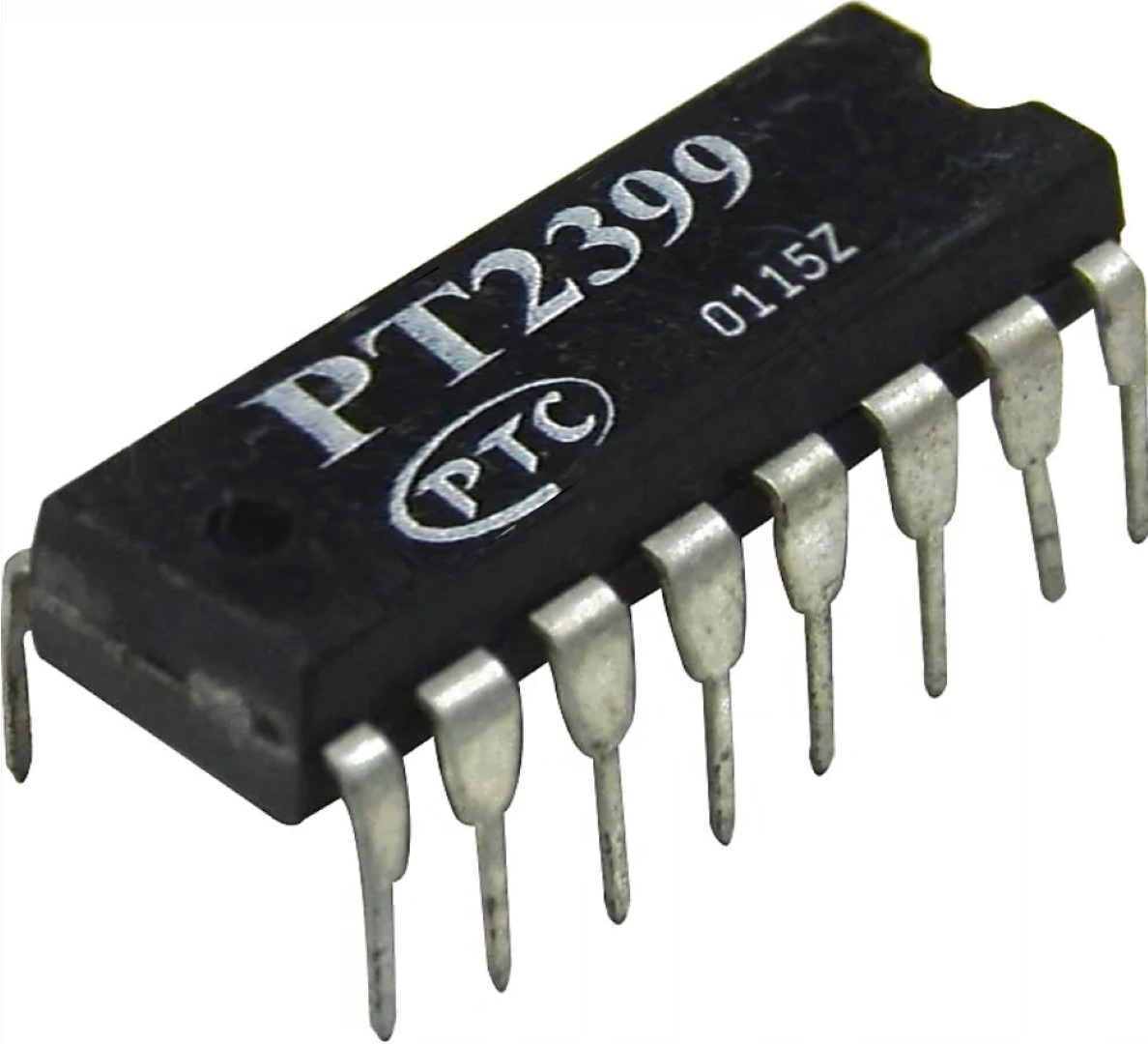
I also recently ordered some cool chips from this supplier in Germany http://www.banzaimusic.com/home.php including the PT2399 delaychip, voltage controlled filters, oscillators, an ADSR, noise, echo, flanger, voltage multiplier/divider/inverter, et al.
I have also built a ORCA inspired drum machine for the serial monitor in Arduino:
/*

soundBox

A visual and interactive sound sequencer in the Arduino Serial Monitor

*/

char array [10][20]; // our screen

void setup()
{
  Serial.begin(115200); // fastest possible Serial Speed in order to "render" our screen quickly
  pinMode(8, OUTPUT); // piezo pin

  Serial.println();
  Serial.println();
  Serial.println();
  Serial.println();
  Serial.println();
  Serial.println();
  Serial.println();
  Serial.println(" ~ Welcome to soundBox ~");
  Serial.println("available commands: i, r, t "); // Serial print list of available commands for user
  Serial.println();
  Serial.println();
  Serial.println();

  delay(3000);

  int rows = 10;
  int columns = 20;


  //FILL THE ARRAY WITH DASHES

       for (int  i = 0; i < rows; i++)
   {

       for (int  j = 0; j < columns; j++)
   {

         array[i][j] = '-';
         Serial.print(array[i][j]);

       }

     Serial.println();
   }

      Serial.println();
      Serial.println();
      refresh(array);
      print(array);
   }


void loop()
{
      listen(array);
      Serial.println();
      Serial.println();
      refresh(array);
      print(array);

  //indices(array);
}

void refresh(char array[10][20]){

int columns = 20;
int rows = 10;
int xCounter = 0;


//CHECKS TO SEE IF WE NEED TO PLAY ANY SOUNDS, I.E. IF ANY '+' IN THE COLUMN TO THE RIGHT
        for(int i=0;i<rows;i++){

          if(array[i][19] == '+')
          {
           xCounter++;  //increment x counter
          }
        }

  //BASED ON HOW MANY '+'S WE FOUND IN THE FINAL LINE, PLAY DIFFERENT SOUNDS

  //MAKE THIS PLAY A SAMPLE INSTEAD OF NOTES?

  switch (xCounter) {
  case 1:
    //do something when var equals 1
    tone(8, 100, 100);
    delay(100);
    break;
  case 2:
    //do something when var equals 2
    tone(8, 200, 100);
    delay(100);
    break;
  case 3:
    //do something when var equals 3
    tone(8, 300, 100);
    delay(100);
    break;
  case 4:
    //do something when var equals 4
    tone(8, 400 , 100);
    delay(100);
    break;
  case 5:
    //do something when var equals 5
    tone(8, 500, 100);
    delay(100);
    break;
  case 6:
    //do something when var equals 6
    tone(8, 600, 100);
    delay(100);
    break;
  case 7:
    //do something when var equals 7
    tone(8, 700, 100);
    delay(100);
    break;
  case 8:
    //do something when var equals 8
    tone(8, 800, 100);
    delay(100);
    break;
  case 9:
    //do something when var equals 9
    tone(8, 900, 100);
    delay(100);
    break;
  case 10:
    //do something when var equals 10
    tone(8, 1000, 100);
    delay(100);
    break;
  default:
    // if nothing else matches, do the default
    noTone(8);
    delay(100);
    break;
}

xCounter = 0; // reset the counter

    /*

 //LOOPS THE LINES AROUND SHIFTING TO THE LEFT
for(int j=0;j<rows;j++){
    int temp = array[j][0] ;
        for(int i=0;i<columns;i++){
            array[j][i]=array[j][i+1];
        }
    array[j][19] = temp ;
    }
}

*/


 //LOOPS THE LINES AROUND SHIFTING TO THE RIGHT

for(int j=0;j<rows;j++){
    int temp = array[j][19];
        for(int i=19;i>0;i--){
            array[j][i]=array[j][i-1];
        }
    array[j][0] = temp ;
    }
}


void listen(char array[10][20]){

int columns = 20;
int rows = 10;

int incomingByte = 0; // for incoming serial data

  if (Serial.available() > 0) {
    // read the incoming byte:
    incomingByte = Serial.read();
  }

    //Here are the functions that modify the array:

  switch (incomingByte) {
  case 'r':

    //print a pattern when var equals 'r'

       for (int  i = 0; i < rows; i++)
   {
       for (int  j = 0; j < columns; j++)
      {
            array[i][j] = '+';
         if (i%2 == 0 && j%3 == 0)
         {
            array[i][j] = '-';
         }
      }
   }
    break;

  case 'i':

    //invert the array when var equals i

    for (int  i = 0; i < rows; i++)
   {
       for (int  j = 0; j < columns; j++)
        {
         if (array[i][j] == '+') {
            array[i][j] = '-';
            }

         else{
            array[i][j] = '+';
             }
        }
   }
    break;

    //draw a big '+' when var equals t
    available commands: i, r, t
  case 't':

       for (int  i = 0; i < rows; i++)
   {
       for (int  j = 0; j < columns; j++)
       {
         if (i == 4 || j==10) {
            array[i][j] = '+';
            }

         else {
            array[i][j] = '-';
            }
       }
   }
   break;

  default:
    // if nothing else matches, do the default
    // default is optional
    break;
  }
}


void print(char array[10][20]){

  int rows = 10;
  int columns = 20;

         for (int  i = 0; i < rows; i++)
   {

       for (int  j = 0; j < columns; j++)
   {
       Serial.print(array[i][j]);

       }

       Serial.println();
  }
}

// a debugging tool just to get your head around how the cells in our array are numbered
// 0,0 is in the top lefthand corner and 9,19 is in the bottom right
void indices(char array[10][20]){

  int rows = 10;
  int columns = 20;

         for (int  i = 0; i < rows; i++)
   {

       for (int  j = 0; j < columns; j++)
   {
       Serial.print(i);
       Serial.print(' ');
       Serial.print(j);
       Serial.print(',');
       }
       Serial.println();
  }
}
+++++++++++++++++++++++++++++++++++++++++++++++++++++++++++++++++++++++++++++++++++++++++++
As well as a composition generator which picks a random root note, randome scale, and then a random chord progression from a list of euphonic progressions:
int duration = 700;
int pause = 500;
int speakerPin = 8;
                     // 24 notes; A 220 - F 1568 in semitones
int notes [] =      {220, 233, 247, 262, 277, 294, 311, 330, 349, 370, 392, 415, 440, 466, 494, 523, 554, 587, 622, 659, 698, 740, 784, 831, 880, 932, 988, 1047, 1109, 1175, 1245, 1319, 1397, 1480, 1568};

                     //The seven modes starting from I Ionian going to  VII Locrian
int scales [][15] = {
                    {0, 2, 4, 5, 7, 9, 11, 12, 14, 16, 17, 19, 21, 23, 24 },
                    {0, 2, 3, 5, 7, 9, 10, 12, 14, 15, 17, 19, 21, 22, 24 },
                    {0, 1, 3, 5, 7, 8, 10, 12, 13, 15, 17, 19, 20, 22, 24 },
                    {0, 2, 4, 6, 7, 9, 11, 12, 14, 16, 18, 19, 21, 23, 24 },
                    {0, 2, 4, 5, 7, 9, 10, 12, 14, 16, 17, 19, 21, 22, 24 },
                    {0, 2, 3, 5, 7, 8, 10, 12, 14, 15, 17, 19, 20, 22, 24 },
                    {0, 1, 3, 5, 6, 8, 10, 12, 13, 15, 17, 18, 20, 22, 24 },
};

                     // some standard chord progressions
int chordProgressions [][4] = {

                    {0, 3, 4, 4 },
                    {0, 0, 3, 4 },
                    {0, 3, 4, 3 },
                    {0, 3, 1, 4 },
                    {0, 3, 4, 0 },
                    {0, 1, 4, 0 },
                    {0, 5, 3, 4 },
                    {0, 3, 5, 4 },
                    {0, 4, 5, 3 },

};

void setup() {

  Serial.begin(9600);
  pinMode(speakerPin, OUTPUT);
  randomSeed(analogRead(0));
}

void loop() {

  int randomRootNote = random(12);
  int randomScale [15];
  int randomChordProgression [4];

  int myNotes[8];

  Serial.println("Random root frequency is: ");
  Serial.println(notes[randomRootNote]);

  Serial.println("Random scale is: ");

     int randomNumber = random(7); // random number for randomScale loop below
     for (int  i = 0; i < 15; i++) // There is no way in arduino to copy an entire array; doing it element by element here
   {
     randomScale[i] = scales[randomNumber][i];
     Serial.println(randomScale[i]);
   }

    Serial.println("Random chord progression is:");

    randomNumber = random(8); // random number for randomChordProgression loop below
     for (int  i = 0; i < 4; i++) // There is no way in arduino to copy an entire array; doing it element by element here
   {
     randomChordProgression[i] = chordProgressions[randomNumber][i];
     Serial.println(randomChordProgression[i]);
   }

      Serial.println("note frequencies in random scale are: ");

      for (int  i = 0; i < 15; i++) // There is no way in arduino to copy an entire array; doing it element by element here
   {
      myNotes[i] = notes[randomRootNote + randomScale[i]];
      Serial.println(myNotes[i]);
   }


  for (int loops = 0; loops < 10; loops++){

  for (int i = 0; i < 4; i++) // plays the triads of the chord progression
  {
   int triad [3];
   triad[0] = myNotes[randomChordProgression[i]]; //root note
   triad[1] = myNotes[randomChordProgression[i] + 2];  // third
   triad[2] = myNotes[randomChordProgression[i] + 4] ; // fifth

   tone(speakerPin, triad[random(2)], random(200, duration)); //plays a random note of the triad
   delay(random(100, pause));

   tone(speakerPin, triad[random(2)], random(200, duration)); //plays a random note of the triad
   delay(random(100, pause));

   tone(speakerPin, triad[random(2)], random(200, duration)); //plays a random note of the triad
   delay(random(100, pause));

   noTone(speakerPin);
   }
  }
}
+++++++++++++++++++++++++++++++++++++++++++++++++++++++++++++++++++++++++++++++++++++++++++
Idea No.1
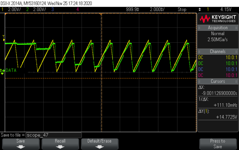
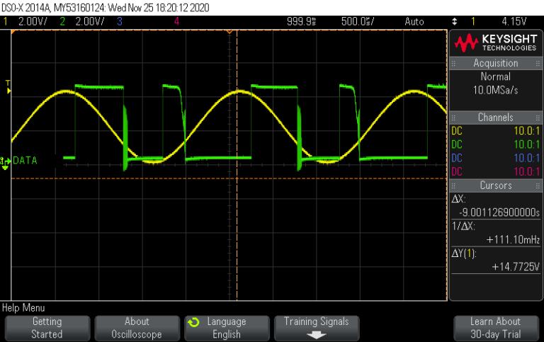
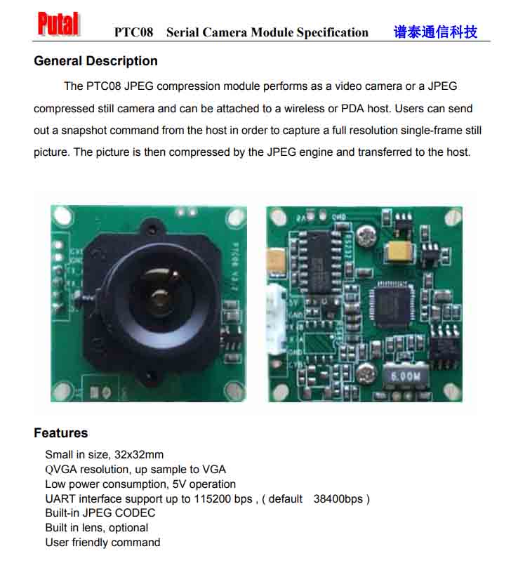
I have already worked a bit with this camera (https://learn.adafruit.com/ttl-serial-camera/):
It took a while to tame but it has delightfully glitchy output:
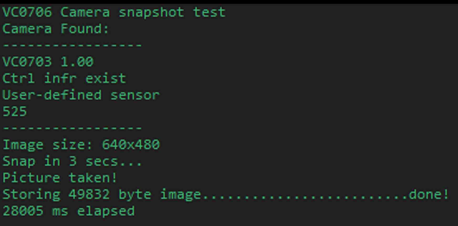

It has a chip onboard which compresses raw pixel data into JPEG file format. I wonder if I could listen in with a logic analyzer and get some kind of visualization of the buffer inside this chip as it goes through the steps (quantizing etc.) of compression.
Idea No.2
A more traditional video synth like the RGB from Bleep Labs (https://bleeplabs.com/product/3trinsrgb1/) but with an interface requiring more digital fab :
Idea No.3
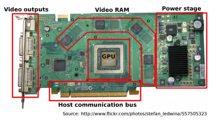
Create a kind of synth that can control various circuit bends (by turning on MOSFETS that make glitchy connections with a microchip) in a GPU similar to this Super NES synth:
I could start by messing with my GPU manually
Idea No.4
Create a device which introduces noise into any signal and then begin exploration possible datastreams to glitch and represent. Opto Glitch exposes the optocoupler to outside light essentially contaminating the signal in a delightful way:
https://github.com/UniQHW/OptoGlitch
Planning
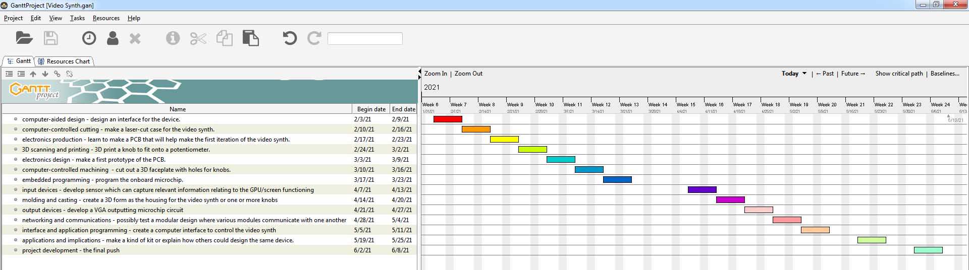
I could incorporate this project into the Fab Academy like so:
Feb 03: computer-aided design - design an interface for the device.
Feb 10: computer-controlled cutting - make a laser-cut case for the video synth.
Feb 17: electronics production - learn to make a PCB that will help make the first iteration of the video synth.
Feb 24: 3D scanning and printing - 3D print a knob to fit onto a potentiometer.
Mar 03: electronics design - make a first prototype of the PCB.
Mar 10: computer-controlled machining - cut out a 3D faceplate with holes for knobs.
Mar 17: embedded programming - program the onboard microchip.
Mar 24: mechanical design, machine design -
Apr 07: input devices - develop sensor which can capture relevant information relating to the GPU/screen functioning
Apr 14: molding and casting - create a 3D form as the housing for the video synth or one or more knobs
Apr 21: output devices - develop a VGA outputting microchip circuit
Apr 28: networking and communications - possibly test a modular design where various modules communicate with one another
May 05: interface and application programming - create a computer interface to control the video synth
May 12: wildcard week -
May 19: applications and implications - make a kind of kit or explain how others could design the same device.
May 26: invention, intellectual property, and income -
Here is the schedule in GANTT:
Attribution
CC BY
