Par-fect Cleaner Final Project
All final project files including CAD designs, PCB boards and more are attached in this ZIP folder. I have also included the Eagle libraries that I used in each one of my PCB boards. All final project files found in this folder. Final Project files
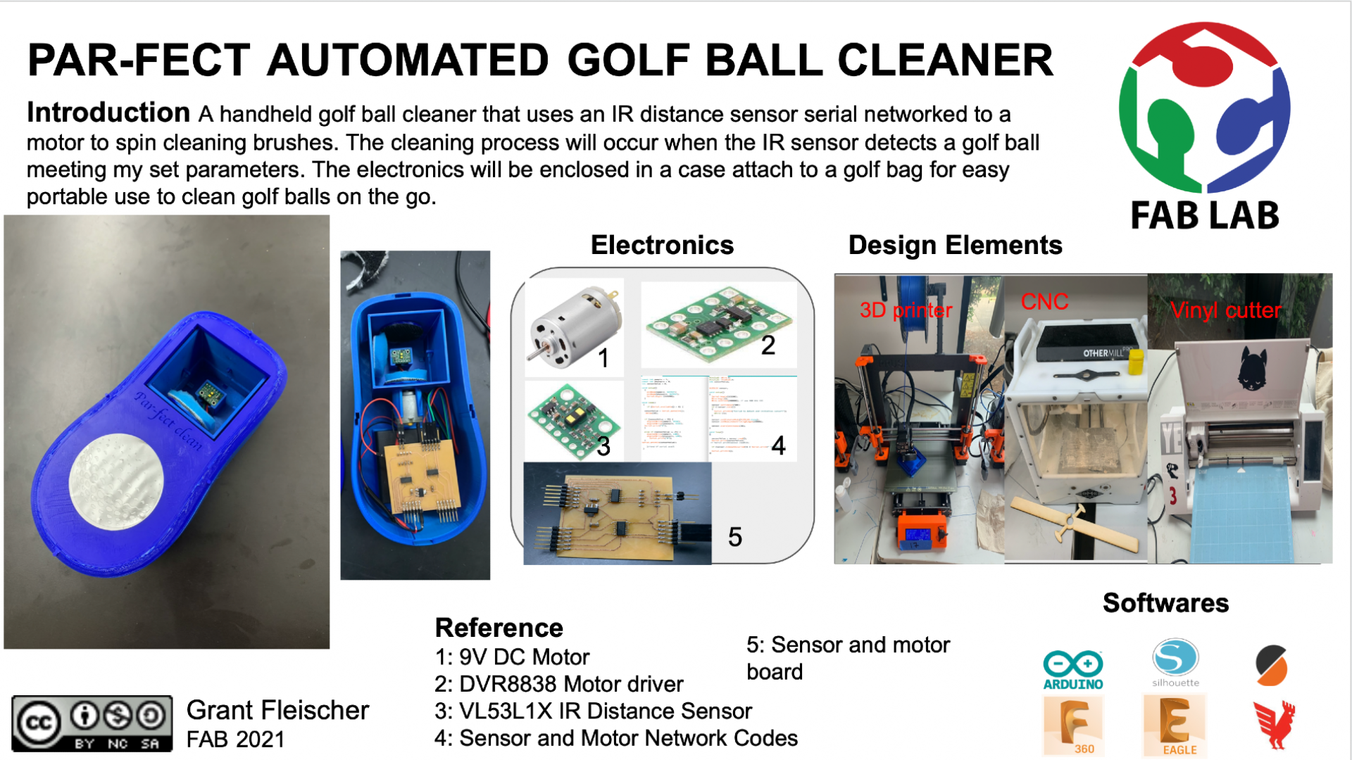
Slide and Video
Licensing
For my final project I will use a Creative Commons-Attribution-NonCommercial-ShareAlike license (CC BY-NC-SA). This license allows my final project to remain open source. I will still have a license on my project to prevent people from using it for commerical purposes and earning money off of its distribution, however anyone will be able to use my files and remix them.

Idea
I want to create a handheld golf ball cleaner that uses my input board (ir distance sensor) and output board (motor with driver board) that are networked to make the motor spin brushes with various strengths of cleaning brushes on them when the IR sensor detects something (golf ball) in very close proximity. These electronics will be enclosed in a case about the size of a multimeter that can attach to a golf bag for easy portable use. I have not yet decided if I want to mold and cast a case or 3D print a case. For my assembly, I want to use various mounts for PCB as well as a battery pack with a regulator to power all my electroncis.
Resources
Sketches
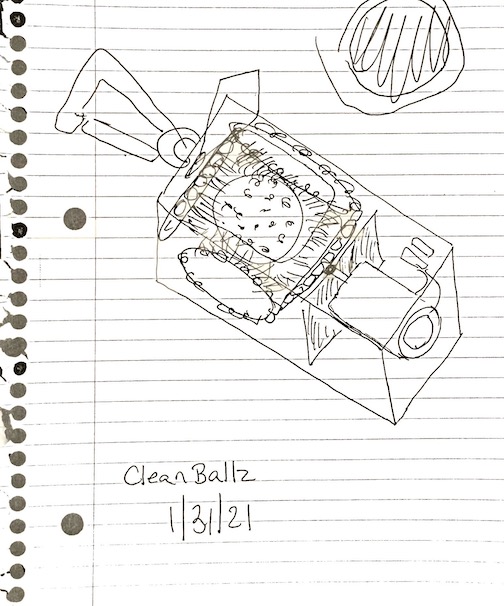
Above is a first iteration sketch of what I envision the golf ball cleaner to look like. This sketch shows a general design of what I want the completed device to look like.
I have not yet decided if I want to mold and cast a case or 3D print a case. The gears cleaning the gold ball will be beveled and resemble a shape similar to a differential from a car. I am going to laser cut an acrylic window on the cleaner to prevent the golf ball from being popped out during the cleaning process. In order to clean the golf ball, I want to connect various strength levels of brushes to the gears.
3D Render
Stages
Electronics
First Attempt
These boards that I created where used during the networking weekly assignment. I planned all along to use these boards however during my final project. I created two boards. Both boards correspond to the input and output devices that will be used in my final project. I am going to use hardware serial to network my two boards to have them function and communicate. Completing networking week allowed me to have the electronics portion of my final project completed so that when a golf ball is inserted, the time of flight sensor is printing serial data and when the data triggers one of the parameters I wrote in my function, the motor powers up to begin cleaning the golf ball. In order to connect my boards, I had to connect the boards via TXD and RXD to transmit and receive serial data as well as connect both boards to power and share a common ground. I did this by rigging together jumper cables connected to an arduino that I uploaded Jtag2UPDI onto. The schematics for both of these boards can be found on my input week 10 and output week 12 detailing the schematic I created and the data sheet and information for the sensors and breakout boards I used. The time of flight sensor is used to get the distance away from the IR waves certain objects are and in my code I am going to use this value in an if statement so that if the golf ball is inserted, the cleaning process will begin.
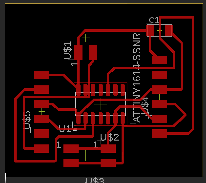
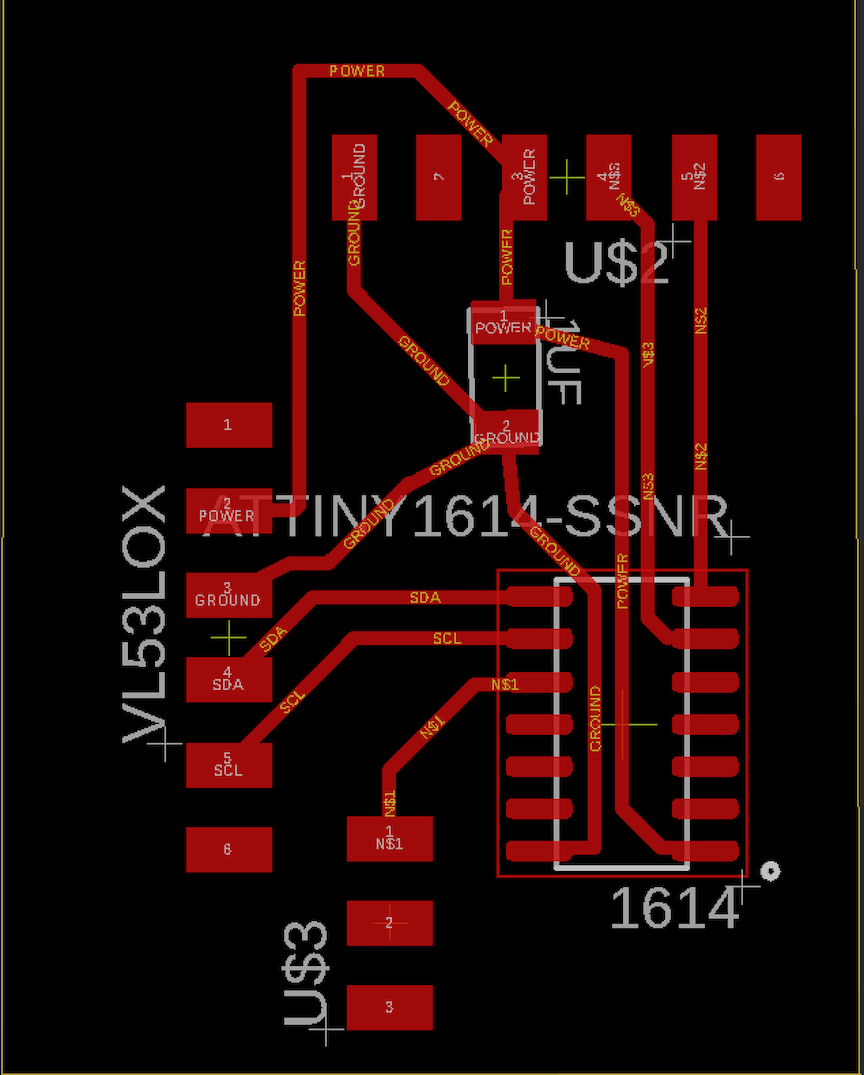
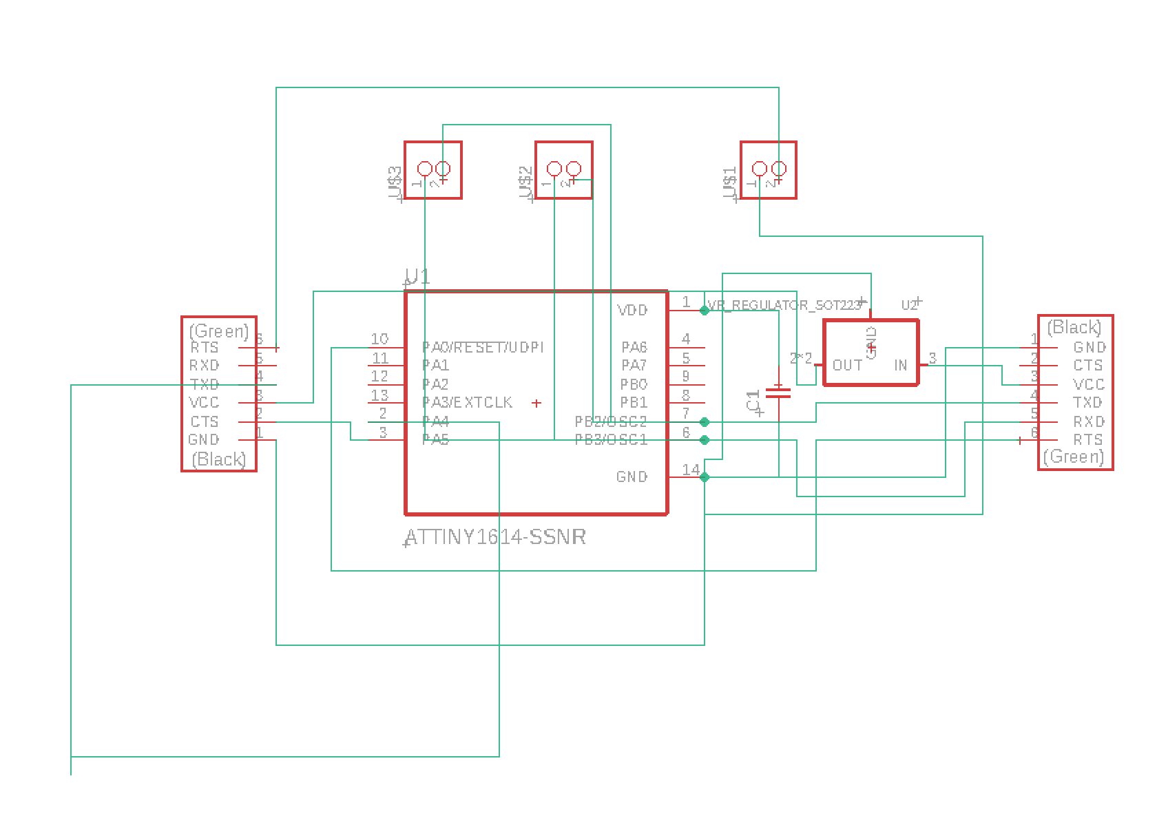
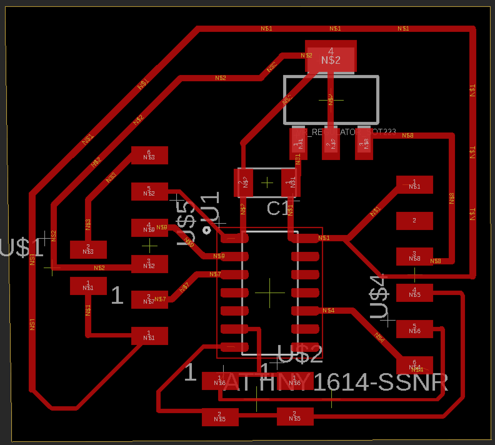
Above are the schematics that I used for both my input and output boards. These are the boards I networked and connected the breakout components to in order to make progress towards my completed final project. Both of these boards were designed in Eagle CAD using various libraries containing the components that I needed for my electronics. I had to first create the schematics while referencing the pinnout of the 1614 then convert the completed schematic to a board file. Once I converted it, I organized the components into a layout that I was satisfied with. Once I finsihed organizing the board file, I exported it to mill and solder.
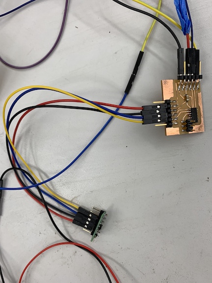
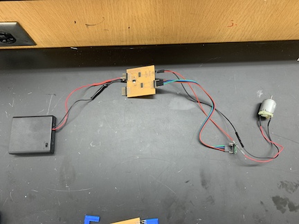
Above is an image of the same sensor board from week 10 that I created and programmed except I am connecting it to the motor driver board via TX and RX pins, a common ground, and power. I am going to combine my code from the IR sensor with the motor driver code and add a loop to allow it to network and function as desired.
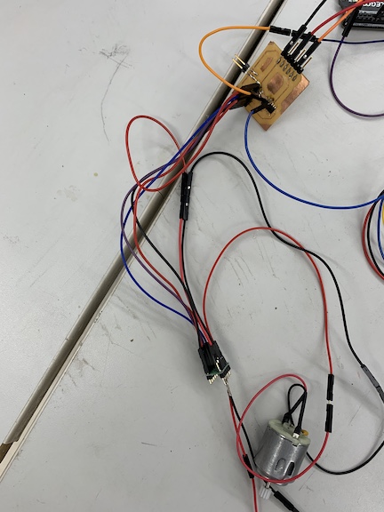
The image above is the same output board from week 12 connected. I have my board that I created connected to my motor driver board connected to a motor. I had to solder a male to female jumper cable to the TX and RX pins of this processor so that it could communicate with the sensor board.
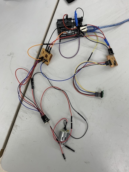
Above is an image of both input and output boards connected to the arduino. I had to connect a common ground and a power between the two boards back to the 5V of the arduino and ground. I also had to connect the UPDI pins to the processors I am coding. I am going to begin creating code to allow these boards to function in sync.
While testing final project electronics, I encountered a problem were the power source I was going to use was too many volts. I then added a 5 volt regulator to one of my boards to convert my 9v power supply to a sustainable 5 volts for the 1614 processor. I am going to route the traces on this board then mill it and solder for my final project.
While testing my final project, I realized that I needed to still to add a 5 volt voltage regulator. I first refrenced what the differnt pins on the regulator did before adding it to my schematic. I needed the 12 to 5 volt regulator becuase I had to power my golf ball cleaner with a 9 volt battery. Previously, I had been using a 5 volt USB port on my computer that I connected to an FTDI board. Once I added my regulator to the schematic, I connected the input voltage, output voltage, and ground pins. Finally. I switched from the .sch to .brd file and routed the regulator traces. Afterwords I milled and soldered the boards.
Milling process Input
In order to begin the milling process I first had to download my board files and open them on the bantam tools software which is what I used to mill out the board on our CNC’s. Once importing the board I positioned it on the bed where it would save the most space on the PCB allowing for others to cut. I then used nitto tape to fasten the PCB material to the bed of the CNC to prevent movement. Once this was completed, I clipped the conductivity clip to the material and inserterted the engraving but (.005mm) into the spindle. I had to select the tool and locate it. Once this was done I propped the material thickness and began milling the traces of the board. I repeated this same process with a 1/32 end mill bit but instead of engraving traces I cut out the board.
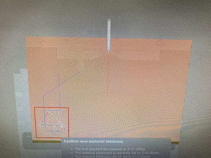
Above is the mill file positioned on the bed of the PCB material. This step was right before I located the first tool (.005 engraving bit) to mill out the traces of my board.
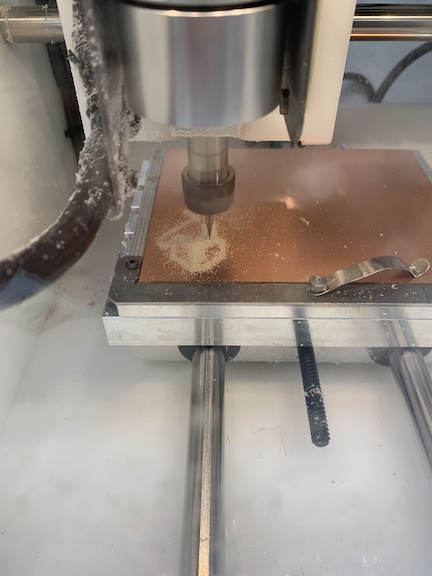
This is an image of the CNC engraving the traces on the board. After this is complete I switch the bits to the 1/32 bit to cut the board out.
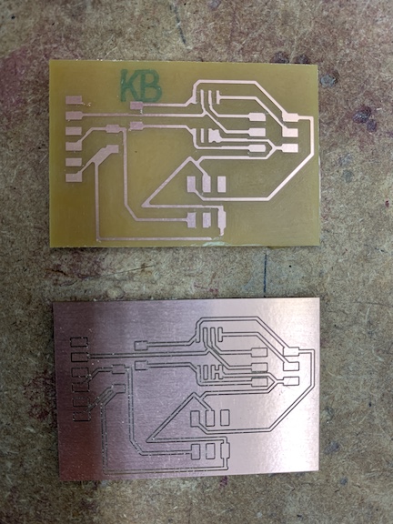
This is an image of two different board styles I milled. The one where it is only copper traces is done by changing the trace clearance to a number such as 20 that will use the 1/32 bit to mill off all excess copper except traces created by .005 bit. I thought this design looked very neat and had never done it before but ultimately stuck to the bottom board which completed the regular way of using the .005 to do the traces and 1/32 to cut the board out.
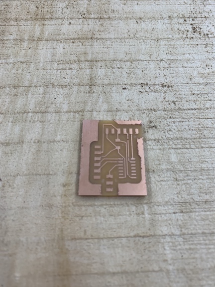
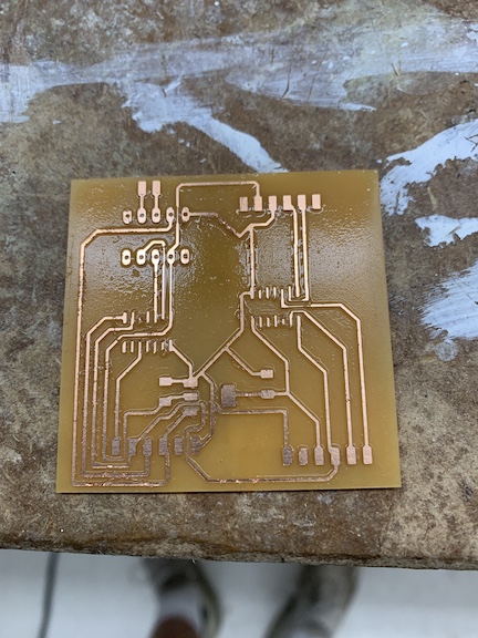
Above is the finished milling process. I set the trace clearance to 2mm to give me a little room to solder to prevent shorts onto the board. I used the 1/32 bit to mill the outline of the board and the excess copper that was milled away and used an engraving bit to mill out the pads. I followed the same process as documented above and used the new schematic. I cleaned the finished product up with an exacto blade and washed it off before soldering.
Soldering Input
The soldering process for this board was rather quick. I only had to solder 3 sets of surface mount headers along with the attiny45 processor and 1 resistor and 1 capacitor. I soldered two boards throughout this week, the first board encountered a small bridge that resulted in a torn trace but the second board was completed with no problems. I used the lab’s soldering iron along with flux to complete the solder for this board. Due to the shape of my sensor it will be connected via jumper cables to the headers on the top side of the board.
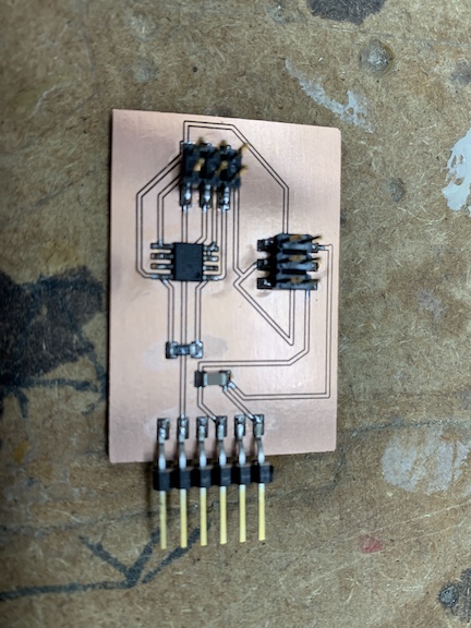
The image above shows each component soldered except for the sensor itself as I had to order it on amazon and the delivery is scheduled for tuesday. Once the sensor arrives I will connect it to the board and program it. I have soldered in the photo all the headers, the chip, the resistor, and capacitors all without problems. I later relized this board was shorted out and re-milled a new board.
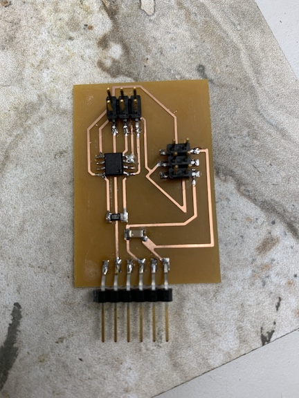
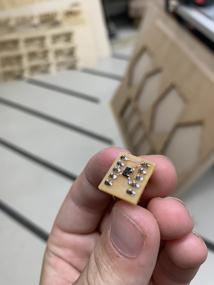
Above is the new board I milled after the unresolved short in my previous board. I used the technique of removing the copper that I failed at earlier to prevent the possibility of more shorts. I soldered this board rather quickly and used a multimeter to test the entire board for shorts when connected to a programmer via corresponding pins as well as ensuring 5 volts was flowing through the processor. I will now begin to upload a code to verify that the board works before attaching the sensor.
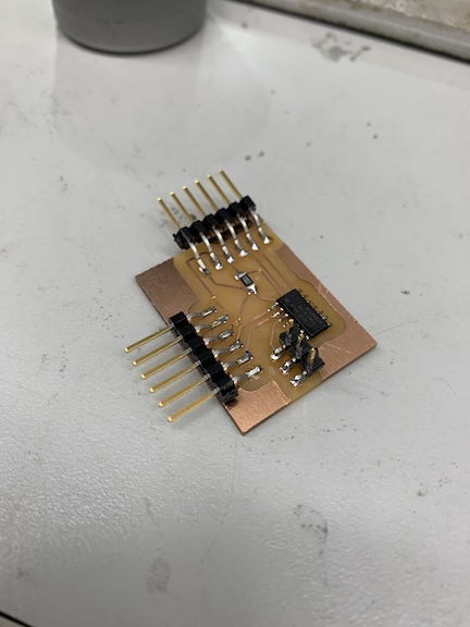
The image above is the completed soldered board for input week. I had the 1614 processor in the center of the board. I soldered this component first to ensure no tight spaces would have to be soldered later on. I used flux paste to ensure that I could easily remove bridges if they form. I did not encounter any errors on this board while soldering. I also had to solder a 1uf capacitor between the power and ground to smooth out current. I lastly soldered UPDI pins and pins to connect my breakout board.
Milling process Output
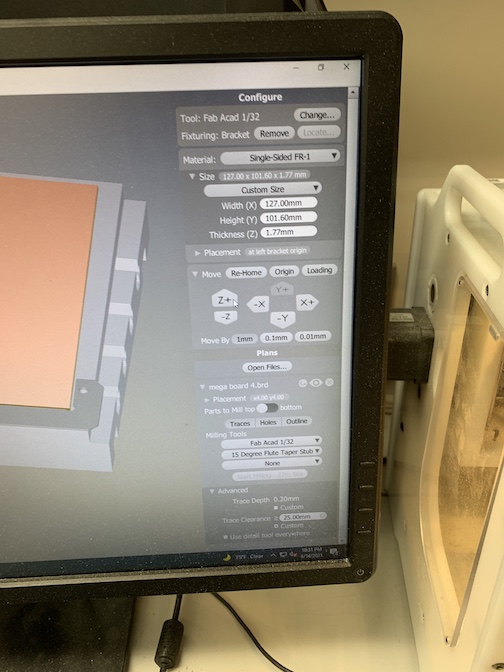
When it came time to mill my schematic that I created, I first had to open my board file on the CNC machine. I positioned it where I wanted it on the material that I was using which was a single sided copper PCB board. I then had to select the first tool I was going to use which in my case was the 15 degree fluted stub bit which I was using for engraving. Then I had to locate the tool. The CNC does this step on its own. Once the tool was located I had to probe the material thickness. This is done by electrically connecting the bed and probing its thickness. I encountered an error here where the machine either registered incorrect values or did not probe at all. I attempted to troubleshoot this error by restarting the machine and the computer as well as exiting and re opening my file. None of these solutions worked and till this day they still have not yet been fixed. I worked around this error by using a caliper to measure the PCB thickness then adding an offset value for the width of the tape. I was finally ready to mill. I decided last minute to create an offset on my traces to allow for easier soldering. This is done by setting a trace clearance then adding the Fab 1/32 bit to mill extra copper. All I needed to do for this is switch the bits after the engraving is completed. While milling the engraving bit worked but when it came to the 1/32 bit the values I imported caused it to mill to deap. This ultimately made my board have lots of copper burs in it. Although it looked messy, I was able to clean it up nicely and make it end up working. I rinsed the board off then scraped excess copper with an exacto blade.
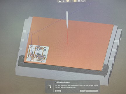
Above is an image of the rendering of the toolpaths for my schematic. I ultimately set the trace clearance much lower from 20mm to 2mm to save more time in the milling process. Above is the result of the 1/32 end mill bit milling away excess copper and can be found in the bantam tools menu under advanced settings.
Soldering Output
When it came time to solder my completed board I was unsure it would work due to the subpar mill that was a result of incorrect material depth. I first referenced my schematic to see which was to orient the processor. I was starting with the inside components to prevent clustering. Once I knew which way the processor needed to line up, I taped it down. In order to find each component I searched our labs inventory in a spreadsheet provided to us. I applied flux to my board and then began soldering the processor. I first tacked down one corner and lined it up. Then I soldered the opposite corner. Once I was assured it was in line I soldered the remaining pins making no bridges. After the processor was complete I began with the rest of the components. For this schematic I needed 2 sets of 6x1 headers and a 1uf capacitor. I then soldered the capacitor with no problems. Finally I soldered the headers. Once this was completed, I was ready to program.
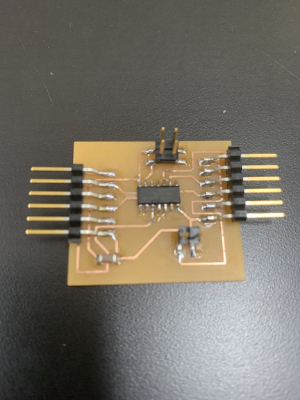
Above is an image of my completed output board. As you can kind of see from the image, the traces are still not clean cut but they did not cause any problems. Next I am going to connect my board and begin attempting to program it to complete the assignment.
Coding
In order to benign the coding process for this assignment, I first had to connect both my input and output to one another. I had to connect the two processors via the TX and RX pins. This is necessary because in order for the network code to work, the two processors have to communicate with one another based upon the values in the serial monitor. Once I had all my connections correct, I then connected the common power and ground to an Arduino programmed with Jtag2UPDI. Once it became time to write a code for my two boards I separated the input and output code. I needed to upload one code for the IR sensor and then another for the motor that also had the loop to analyze the serial data. I had very little coding experience prior to this so I struggled in making my code actually work although it compiled correctly. My code for the input board was an edited version of the sample code that would only print serial values after having the sensor initialized. I connected the UPDI pin to the arduino and uploaded this code to the input sensor. Then it was time to write the code for the motor board. I first had to paste in the code I used during output week with a couple edits made to it. I changed the motor values of speed and duration to initially off and then when it detects the correct value, fully on. I had to write an if statement in order to analyze the data. This loop contained a function of Serial.ParseInt so that it would print the values, then I used the incoming byte function so that if the serial values are less than or equal to 25 the motor turns on. This signifies when the golf ball has been placed in the cleaner. Once I had this code completed and compiled I disconnected the UPDI from my input board and reconnected the output board UPDI. Then I uploaded the code successfully. Now it is time to test my code and see if it is functional.
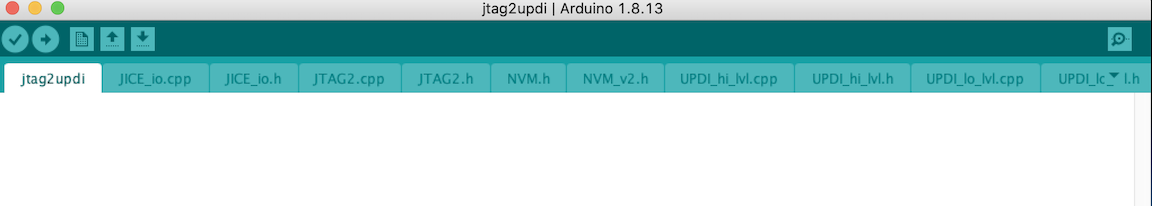
Above is an image of what the Jtag2UPDI sketch looks like when correctly opened in arduino’s software. I then uploaded this to my UNO so that I could use it as a programmer to upload the code to my Tiny1614.
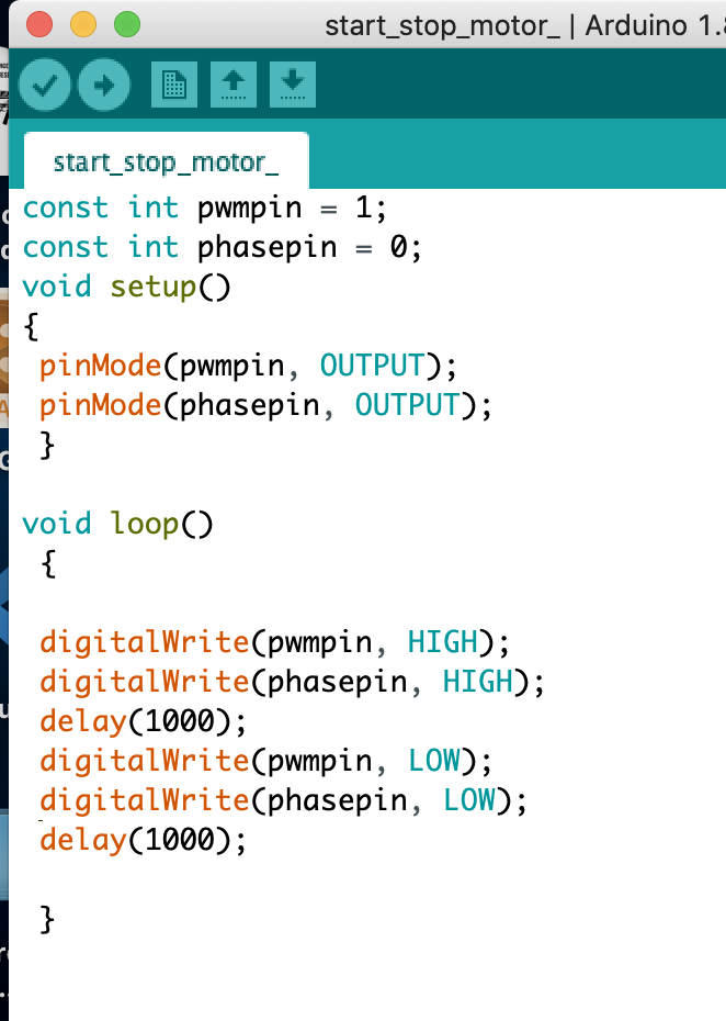
After encountering many errors while attempting to program my motor control board, I tested it by writing a simple code that would turn the motor on and off repeatedly. Above is a screenshot of the segment of code that I wrote.
I also re-wrote the input board code so that each value could be assigned under the variable sensorValue. I edited the code to make this an integer and instead of printing serial.read it printed serial value. I incorporated this variable into my motor board to read the serial data.
#include <Wire.h>
#include <VL53L1X.h>
int sensorValue;


VL53L1X sensor;

void setup()
{
  Serial.begin(115200);
  Wire.begin();
  Wire.setClock(400000); // use 400 kHz I2C

  sensor.setTimeout(500);
  if (!sensor.init())
  {
    Serial.println("Failed to detect and initialize sensor!");
    while (1);
  }

  sensor.setDistanceMode(VL53L1X::Long);
  sensor.setMeasurementTimingBudget(50000);

  sensor.startContinuous(50);
}

void loop()
{

  sensorValue = sensor.read();
  Serial.print(sensorValue);
 // Serial.print(sensor.read());

  if (sensor.timeoutOccurred()) { Serial.print(" TIMEOUT"); }

  Serial.println();
}
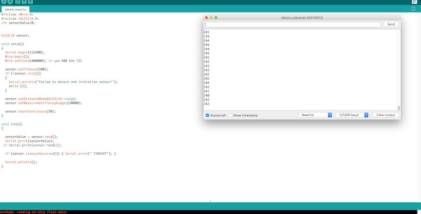
The code segment above is my completed working code that I uploaded to my input board. This code is initializing the library and then setting up the serial read and print statements in the loop so that I can read the data from the sensor about the distance. I know this code works because it worked during my week 10 assignment.
const int pwmpin = 1;
const int phasepin = 0;
int sensorValue = 0;

void setup()
  {
    pinMode(pwmpin, OUTPUT);
    pinMode(phasepin, OUTPUT);
    Serial.begin (115200);
  }

void loop()
 {
    if (Serial.available() > 0) {

  sensorValue = Serial.parseInt();
   delay(10);


  if (sensorValue < 25) {
    digitalWrite(pwmpin, HIGH);
    digitalWrite(phasepin, HIGH);
  Serial.print("A");
  }

  else if (sensorValue >= 25) {
    digitalWrite(pwmpin, LOW);
    digitalWrite(phasepin, LOW);
      Serial.print("B");
  }
Serial.println(sensorValue);

    }//end if serial avail
 }
Above is the code that I used to complete the motor portion. This code not only turns the motor on but also completes the networking aspect of this week’s assignment by reading the sensor values to turn on the motor. This is done by the if statement in the void loop. I also initialized the phase and power pin as well as some other variables. I also had to set speed to 0 and 120 to clean the golf ball. A problem I encountered while attempting to write code for the motor board was not being able to interpret the serial data. In order to troubleshoot this problem, I attempted to write a simple code that printed all serial data the motor received to test if it even worked after a failed attempt of sending the serial values that would trigger the motor via the serial monitor.
When I had to mill a new baord for the final project, the code did not change at all. Both baords were on the same PCB but retained independent UPDI pins. I just swapped the UPDI pin between the two and successfully uploaded both input and output code.
Final Electronics
After realizing the mess of wires and the inconsistency while testing, I decided to combine my 3 baords, sensor input, motor outputm and motor driver boards into one. I did so by copying and pasting their schematics into one file and creating a board that encompassed all of my needs. This greatly helped with wire managment as instead of using ugly jumper cables, now I have traces in the board that I am going to mill to connect each component. To start this board, I first had to re create my sensor board as I encountered a forward backward error. Once I remade it, I copied the output board that I created over into the file. Once they were both together, I needed to establish a common ground between the two boards as well as establish TX and RX connections. Finally, I had to incorperate the 10 pin DIL footprint for my driver board. Ultimately I am going to mount this component on the underside of my top case for good wire management practice.
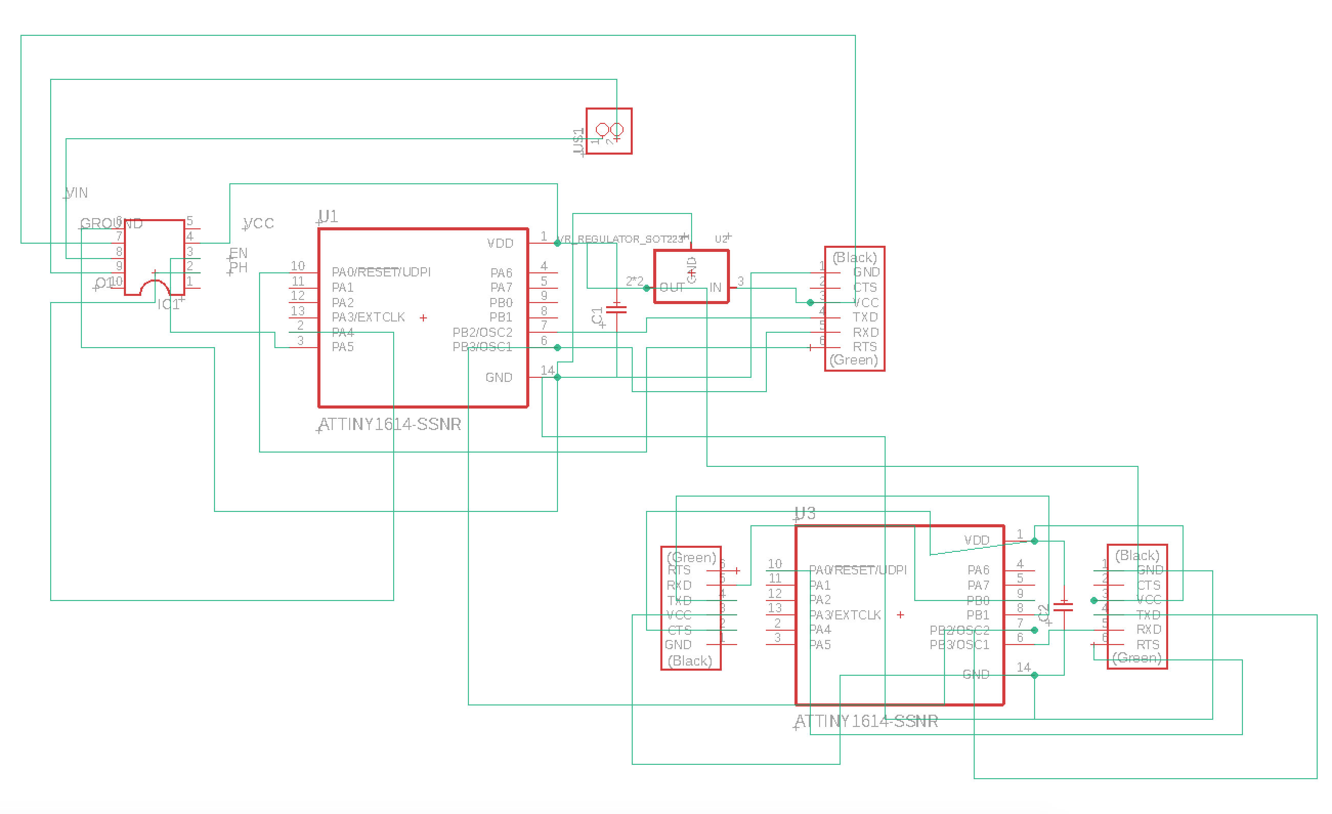
Above is an image of the schematic for the board that is a combination of both my input and output boards. Their are holes for my DIL10 motor driver board as well as headers for my distance sensor and motor. I also am using a 12 to 5 volt regulator to convert my battery pack in order to power both the 2 1614 processors with 5 volts after using the unregulated power to connect to my motor driver board to provide the motor with enough volts to spin. The traces look messy in the schematic file, but I can re organize them in the board file that I must create before I am able to mill out my new input output board.
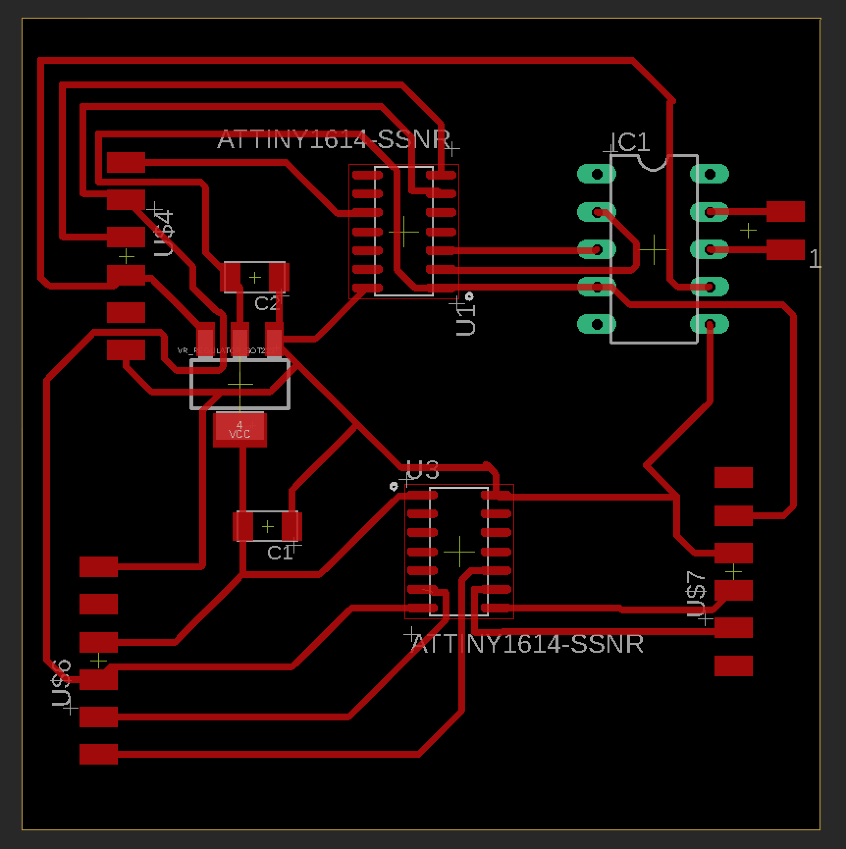
The image above is the final schematic I used for my mega combination board of my input and output baord as well as 10 pin DIL slot for my motor driver board. The schematic took a very long time to route, but I am very proud of the fact that no zero ohmm resistors where used. I set the trace clearence to 16 for almost all of the traces to ensure that the soldering would be easier and that the machine would be able to mill the traces while using the 15 degree fluted bit that I had used in the past. Once I was finished, I exported the file to my google drive to begin milling out the board on my labs CNC.
Batteries
Originally, I started this task with the idea of using a regular 5 volt DC battery to power all of my electronics including a DC motor. After assembling my entire final project, I relized the error in my ways. While testing, I was burning through entire 9V batteries in a matter of seconds. I am solving this error by using a series of AA batteries as this will provide more current for the motor then the 9V could. I had to re design my CAD bottom case to fit the battery pack but ultimately belive it will help the longevity of my project.
Milling new board
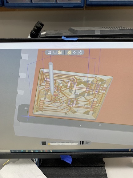
Once I had exported my file, it was time to mill it out on my labs othermills. I first had to log into my google drive account on the computer so that I could download my board file. Once I had downloaded the mega board file, I imported the file into the bantam tools software. At first the traces where filled with red bubbles indicating their was not enough clearence to mill, but after setting the correct bit that I would be using, they dissapeared. Next, I positioned the board file on the software exactly were I wanted it to be milled by imputing values into an X axis and Y axis. After this, I inserted the first bit that I was going to be milling with. I prefer to remove all excess copper from the boards that I mill so in the settings I set the trace clearence to 20mm so that it mills off all the excess copper. To start I instered the 15 degree fluted bit into the collet then tightened. I selected the tool in the menu and then the machine proceeded to locate the bit. Next I probed the material thickness. I encountered an error were some of the CNC probed incorrect thicknesses. I relized this problem after I milled a board that had burrs and uneven traces. I corrected this problem by using a caliper to get the thickness of the material myself and then set an offset for the fastner to the bed of the CNC. Once I was ready to go I began to mill. The 15 degree fluted bit milled the tight areas as well as some of the pads. About halfway through, I had to switch to a 1/32 flat end mill bit to remove excess copper as well as cut out the holes and outline of the board. Finally after about 40 minutes, my board had finished and I removed it using a scraper. I washed my board off with water and then proceeded to the next step of soldering.
Above is an image of the board file after I set the correct settings to use the 1/32 bit to mill off all the excess copper. I like doing my boards this way because it prevents the possibility of me creating bridges with the copper that would have been left there. The pads of this board will be created with the 15 degree bit and the outside will be done with the 1/32 bit.
The image above is what the settings that worked the best for me looked like. While milling, I attempted 5 differnt boards, 2 of which came out nice. Over the course of my attempts, I encountered errors such as not probing right, faulty bits, bad adhession and more. All of which none the less caused the board to fail. I corrected all my problems with these settings after using the caliper to get the correct width of the PCB material.
This video shows the process of the bit milling out differnt areas of my mega board I am creating. As you can see on the screen, their is a digital bit that is showing in real time what areas are being milled. Once the milling is complete, I will wash the board off and begin soldering.
Once I finished milling my board, I removed it from the CNC using a paint scraper and then rinsed it with water. After cleaning up this paticular board with an exacto blade, the traces came out good in my opinion. I let the board dry off before soldering and then fastened it down to my work station to begin. I first tacked down the two processors in their correct orientation.
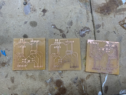
Over the course of attempting to mill the perfect board, I encountered failures. These boards above represent a mixture of the good and the bad. One the boards has lots of frizz from the CNC and came out very messy, This is a result of the trace depth being too high. Another of these boards had a pad rip off. This messed up the board. I ended up using a board that I had to clean up manually a bit but came out good overall.
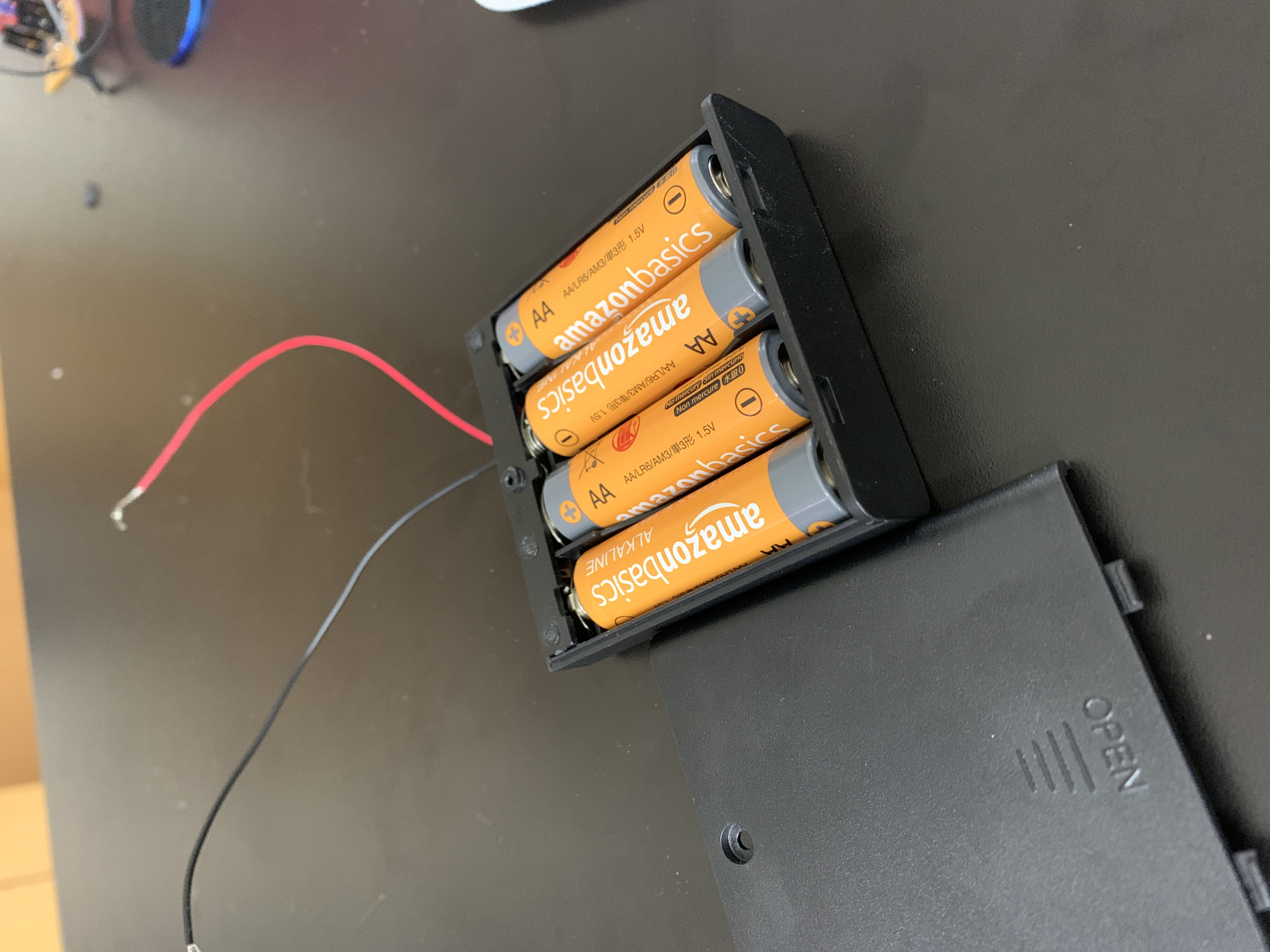
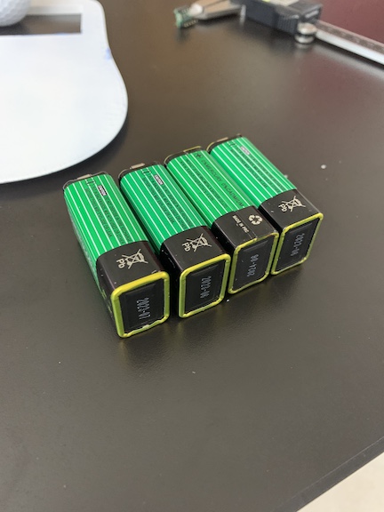
Above is an image of the battery pack that I will be using for my final project. The new battery pack will allow me to power my electronics for much longer periods of time due to the increased current while retaining similar numbers of volts. I tested the motor by connecting it directly to the motor and it in fact spun faster then with the 9 volt. The new battery pack also makes my wire Management much cleaner and aesthetic. I will connect the positive and negative terminals of the battery to jumper caples to connect them directly into the power in on my output board. This way the volts coming in can be converted through the regulator so that the processors can handle the voltage while at the same time giving unregulated volts to the motor driver board.
Above is an image of the completed mega board after I finished soldering it. In order to solder my board correctly and proficiently, I first taped down both 1614’s in their correct orrentation and tacked down the corners. Then I finished carefully soldering the rest of the components with flux and a pointy tipped iron. Then I used the stuffing method and moved out another layer to the next set of components. I then soldered the regulator as well as capacitors. I had to ensure that I did not bridge solder across Components or traces as I soldered. Finally, I soldered on the headers. Due to how I was mounting the board, I decided to use the side mounted headers.
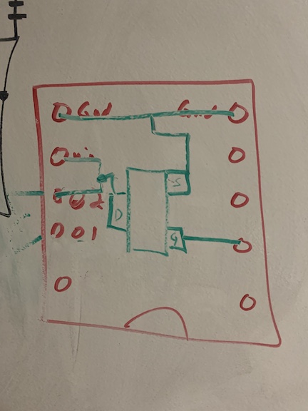
While testing my electronics, my motor driver board that I had been using since I began working on my final project electroncis, failed. Instead of delivering the recommended voltage for the motor, it was hard stuck as 3 volts. due to to the lack of that specific driver board. I turned to eagle CAD and designed my own. I first drew out the schematic of the previous driver baord which can be found below as well as labled in correct orientation, all the pins. I also added a mosfet to act as the phase and enable pins that I previously had. Below is a picture of the sketch.
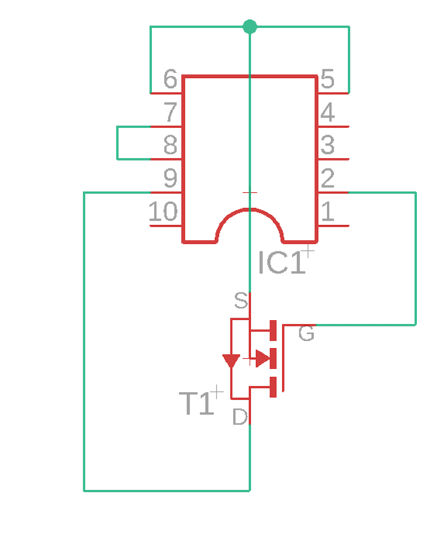
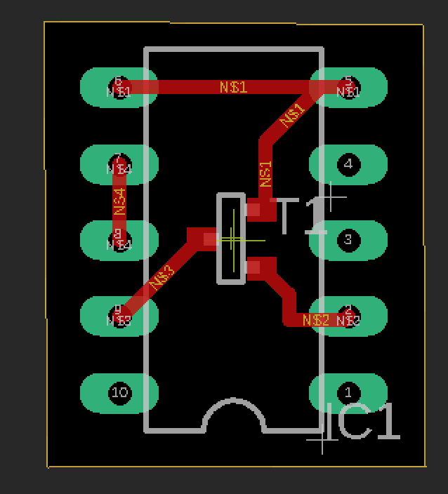
Once I had the sketch as well as an Idea as to what I was going to be designing in eagle, I imported the 10 pin DIL footprint into my schematic. I connected the traces by bridging the grounds and connecting the out2 to the motor power in. I then added in the mosfet and connected the 3 pins according to their pinnout. I tested the pins by drawing out traces to figure out the drain and gate pins on the mosfet. Once this was complete, I converted the schematic to a board file. This was very easy to route and I bumped up trace size to 18 to prevent mistakes. To mill, I used a 15 degree bit and then a 1/32 bit to cut the holes and outline. Once milled, I quickly soldered header pins as well as a mosfet. I later realized that I also needed a Schottky diode to prevent flyback voltage from destroying my board. I soldered the cathode of the diode to the non hot side of the out 1 pin and the annode to the hot of the motor. After some tests, the makeshift driver board worked but ultimatly short term. After errors with constantly alerting the motor to be on, I had to use a differnt motor driver. Below are images of the schematic and board file of my motor driver daughter board.
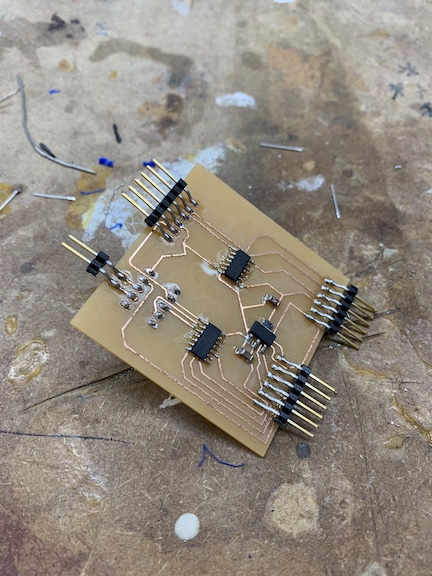
Below is the finished product of the motor driver daughter board after I soldered it. This board attaches to the underside of my mega board and replaced the previous faulty driver board I had before.
CAD
To aid in designing my final project, I created a case in Fusion 360 that would house the electronics and components for my final project. I am creating a top and a bottom part of the case that will snap fit together. The bottom part of the case will have mounts for the motor as well as PCB boards and Time of flight sensor. I designed a window in the case which is were the golf ball will be cleaned. I printed both parts of the case using our Fab Lab’s 3D printers. In the futre I want to look into making my product waterproof using a different filament to print the case components.
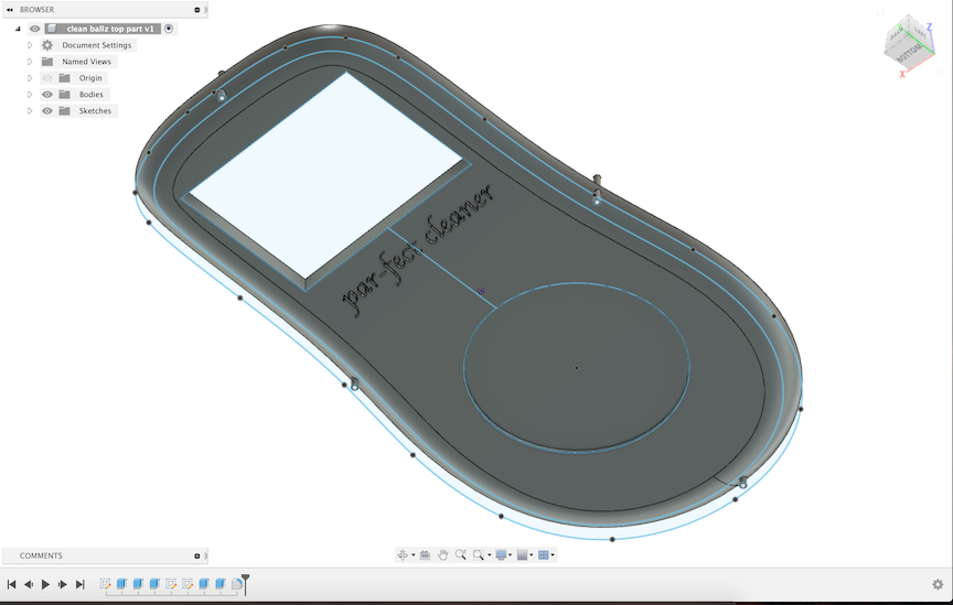
Above is the Fusion 360 rendering of the top part of the case. The circular dimple in the case is were I am going to place a custom sticker of a golf ball using different layers for details. I also used a cursive font to inscribe the product name. I added the pins in the outside of the case that will slot fit with corresponding holes in the bottom case piece. Finally, I added a fillet so that the case feels smooth in your hands and looks sleek. I extruded the top portion 10mm for the top part of the case.
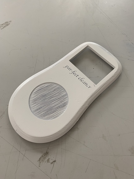
Above is the printed top portion of my case. Although it is printed, I do not envision this as the final iteration of my final case. It did however come out exaclty how I had hoped. After it was printed, I sanded it down to remvoe some of the exterior imperfections and then applied a white primer to the case. I still need to finnalize design elements on the lower part of the case before I can mesh the two components together.
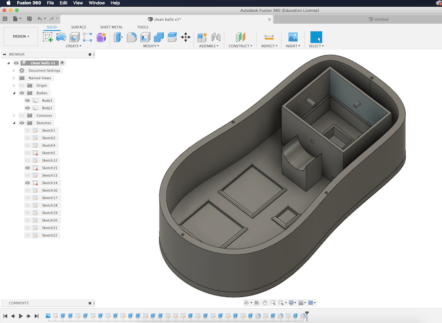
Above is the fusion file that I created for the bottom part of my golf ball cleaner case. I first created the general shape that lined up. The next thing I had to do was create the corresponding holes for the slot fit pins on the top part. When creating the slot for the golf ball I had to measure the diameter of a golf ball. The next thing I created where the board slots to organize my boards. I used a callipar to get dimensions then extruded the slot and filleted it. Next, I added a motor mount that connected into the golf ball cleaning compartment. Once I had all of that completed, I added the pegs that I will fasten the other cleaning brushes onto. I also added a mount for the IR distance sensor so that it can properly register distances to know when to activate the cleaning process.
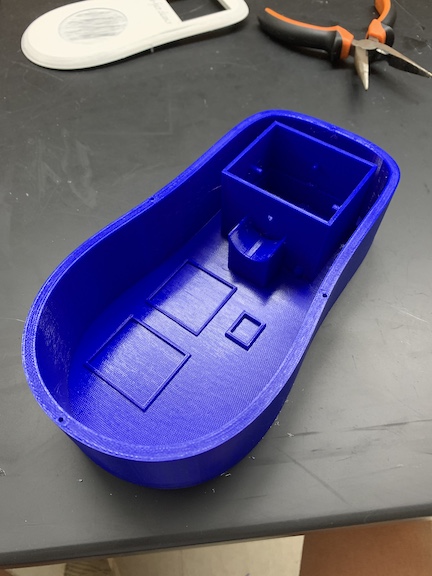
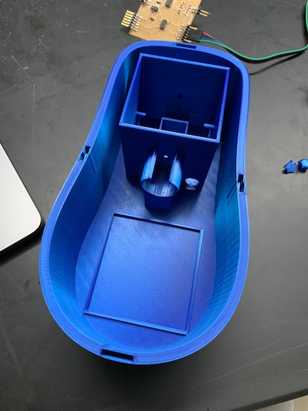
Above is my completed print of the bottom part of the case. I printed this part using PLA on the Prusa MK3S. The print time was approximately 11 hours. After I printed it, I assembled the electronics inside and then sealed the case with the top portion. Now it is time to assemble my final project. I encountered some problems with this first iteration design of the bottom portion. I did not have enough clearance for the pegs to properly slot fit. Another issue I had was no room to route wires. I corrected these problems in a new file that I designed and am going to re print. The new design features increased apertures for better wire routing as well as increased clearence for a better fit.
For my new CAD design I wanted to create a cool fastener to better manage my wiring and clean up my project overall. I decided to create fletcher mounts for both my 9V battery and DC motor. I first designed the file in Fusion 360 then sliced it using our Prusa Slicer. Finally I printed the test file. Once I confirmed they worked as inteneded I used the insert derive feature on Fusion and added it to my final project CAD file.
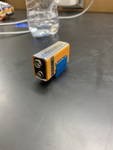
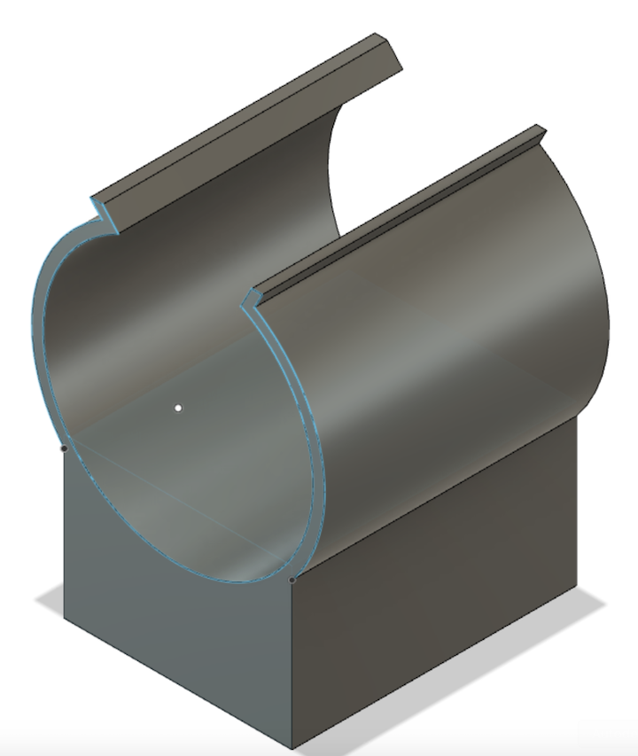
Above is the fastener I created for the 9V battery in its 3D rendered state as well as holding a battery after I printed it demonstrating that it is working. I was thrilled with how it turned out and added it to my final CAD file to be printed.
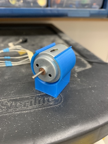
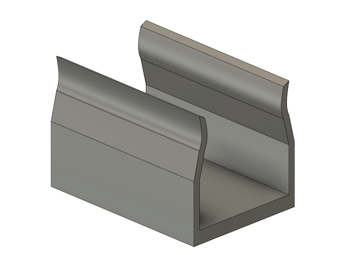
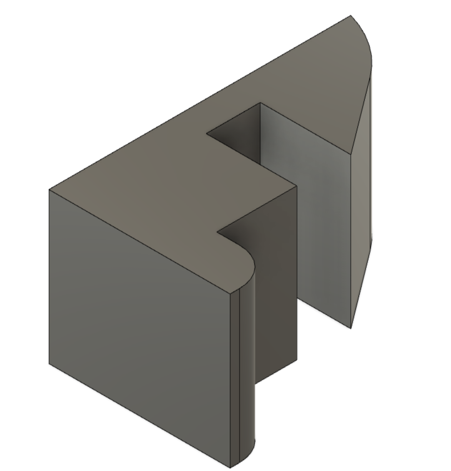
Above are the fletcher mounts I created for my DC motor. I also added these into my final project file becuase I loved the way they turned out. In order to create them I found the diameter of the motor then created the circle. Finally, I cut out the top portion so the motor could be fitted in but once iside, would remain fastened.
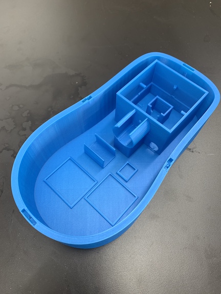
Above is an image of the new case after I printed it. This case design features much improvements over the last. Instead of having to use fasteners for most of my components, I used fletcher fits and snap fit mounts for each of my boards and electronic components. I also impproved the size of the golf ball cleaning window and clearnece of the snap fits. This case design will be what I use in my final design. I need to focus on wire routing and management in order to perfect my final project.
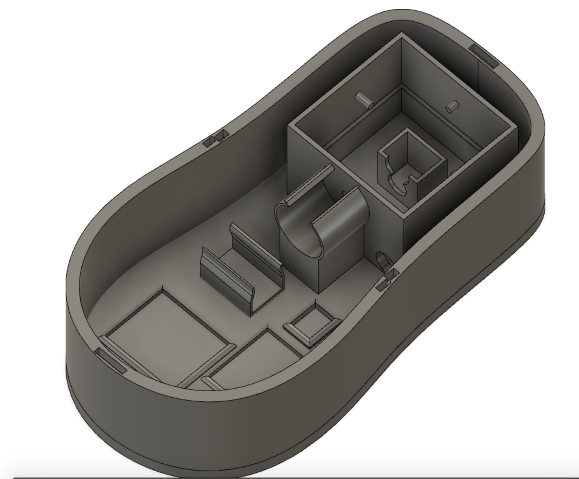
Above is the second fusion body of the golf ball cleaner case. In this version, I have elevated the mounts for the PCB boards I created to better wire managment. I alse increased the ammount of room the golf ball has in the cleaning compartment. I printed this new variant to use with my final project. A small problem I encountered occured with the battery mount. When I printed it originally, the batter was inserted against the print layers causing it to be strong and flex correctly. Now while assembling, I layed the battery with the layer lines causing it to be weaker and break during the flexing process.
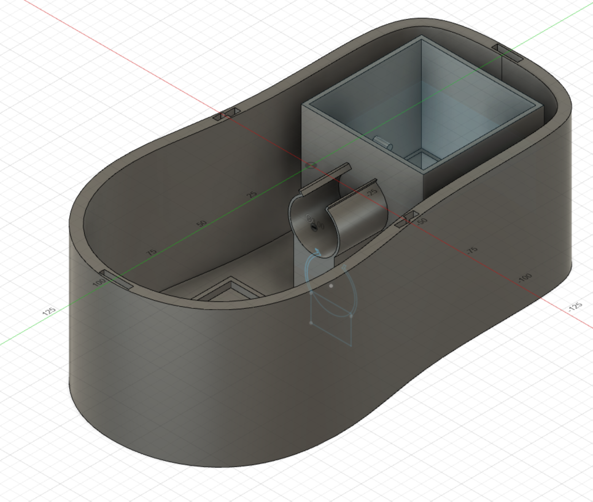
Above is the Fusion final product that I 3D printed to create my case. This design features differnt management for my wires. I am now using a 4 pack of double A batteries instead of one 9 volt battery. I have created a slot for the battery pack. The entire case has been extruded to fit the entire golf ball. Furthermore, I elevated the motor mount so it better hits the middle of the golf ball to spin it. The case for the battery pack I made by using a caliper to create a snap fit case. The battery pack and the motor fit snuggly and the new mega board will fit using fasteners to the top portion of the case. The top piece of the case underwent no changes because it fit perfectly. I did however re print the top portion of the case because one of the pins snapped off.
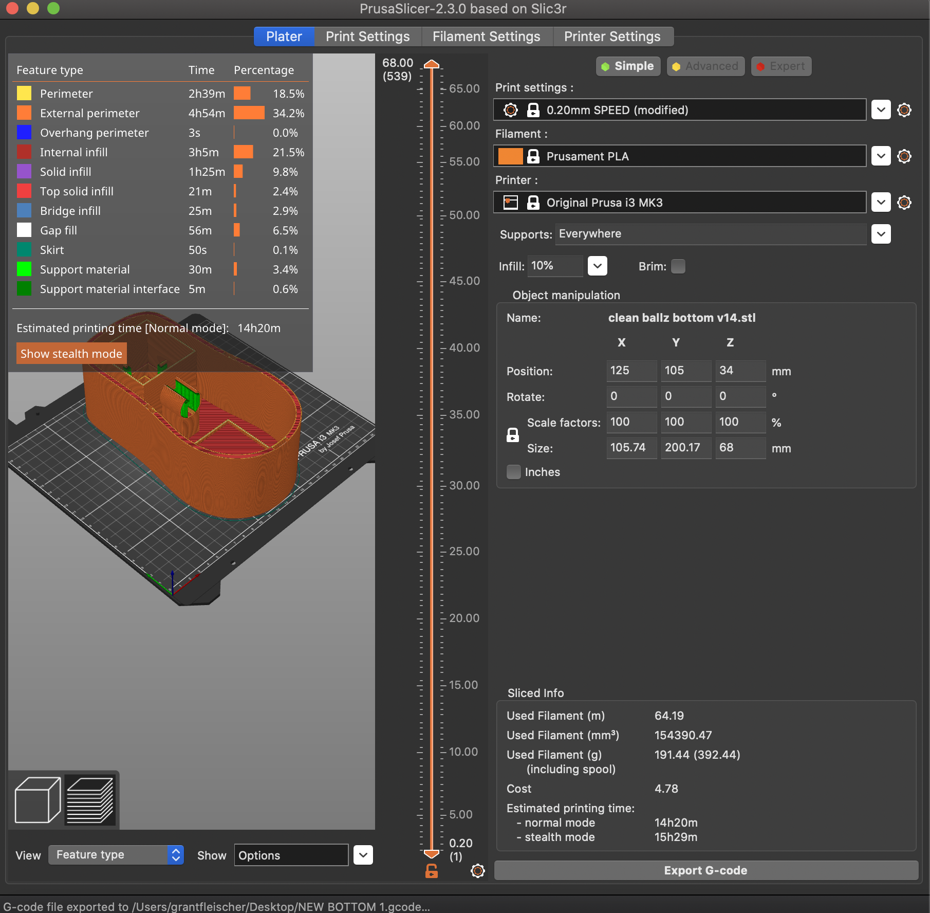
Once I exported my file to print, I imported it into the Prusa Slicer to slected the level of inlay as well as the inlay pattern. While slicing, I saw the ammount of time the print would take to finish as well as were various supports would be printed. For simplicity sake, I selected supports everywhere it recommend. Now I sent the file to Octoprint to print on the prusa.
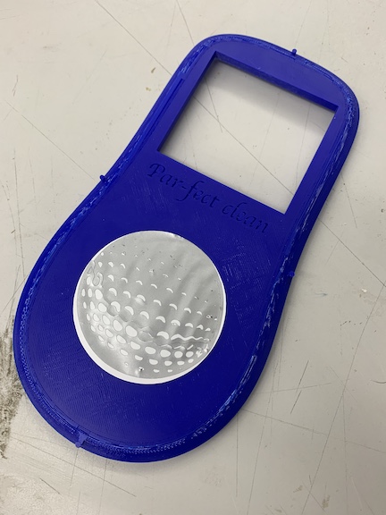
Above is the same top portion of my case as before, I just had to reprint due to a snapped peg for the fitment as well as becuase the old one had become warn on in my periods of test fitting with my jumple of wires. The print took approximately 2 hours and I used 10% infill on the 3D printer. The window on this print is for the golf ball to be inserted into while cleaning. This top portion will snap fit onto my newly printed bottom portion that I made bigger. I also had to remake the sticker using the same file from before. To mix it up, Instead of layering white on silver, I layered silver on white. Once the bottom portion finishes printing I will assemble my final project.
Above is the finished bottom portion of my golf ball cleaner. All the changes turned out as expected. This new design features the increased height to better fit the golf ball, new wire management and snap fit for my one board and 1 battery pack. The print took a total of 16 hours to complete. Now I am going to assemble the electronics inside the new bottom case.
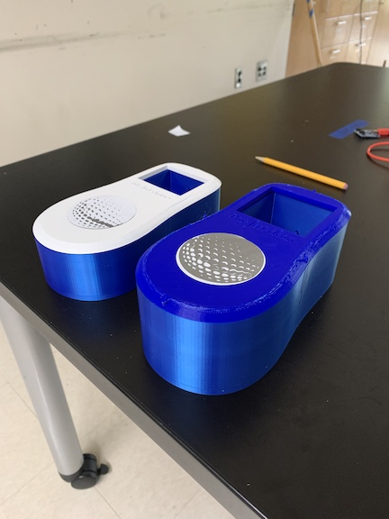
Above is a side by side of the first iteration case compared to the second iteration. As you can see the case on the right hand side is much taller then that on the left. This is because of an error I made on the first design were the golf ball stuck out of the case and the moor was hitting the golf ball below the midpoint. All of these slight corrections have been made in the newest version of my case that I printed. The top part of the case remains the same CAD file as before however and still snap fits very snuggly.
After hearing Neil’s remarks following my oral defense of my project, I decided to create baord mounts to help with my wire management and system integration. I took two differnt design approaches to this task and am going to print and test both of them. The first take I took was the traditional press fit board mount that I have used in previous iterations of my final project CAD. I had these form of mounts in my prototype 1 CAD. Another design I want to try is slot fitting my PCB with little slide pieces. Once I print these pieces, I will attach them to the top CAD and better integrate my system and route my cables.
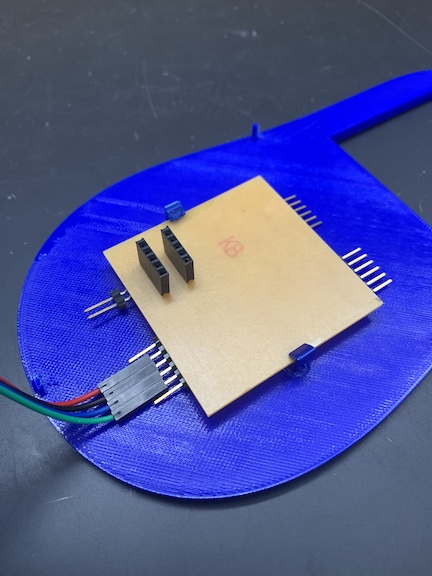
Above is an image of my finished board mounts and their success with the mounted board. I am very happy with the way that these turned out and have seent the affect they have on the system integration of my boards and wires in my final project. Not only do the clips neatly fasten the board, they also hold it tight in place to prevent damage. The print took a total of 5 minutes in our lab and I printed it with 100 percent infill for maximum strength. Below is a video of the secured board.
Sticker

For another aspect of my final project, I wanted to include the subtractive process of creating a sticker. I used the application of Silhouette Studio to create a layered sticker of a golf ball. This is the image I used to trace to create the diifernt layers of my sticker. I want to put the sticker in the dimple I created in fusion on the front side of my project.
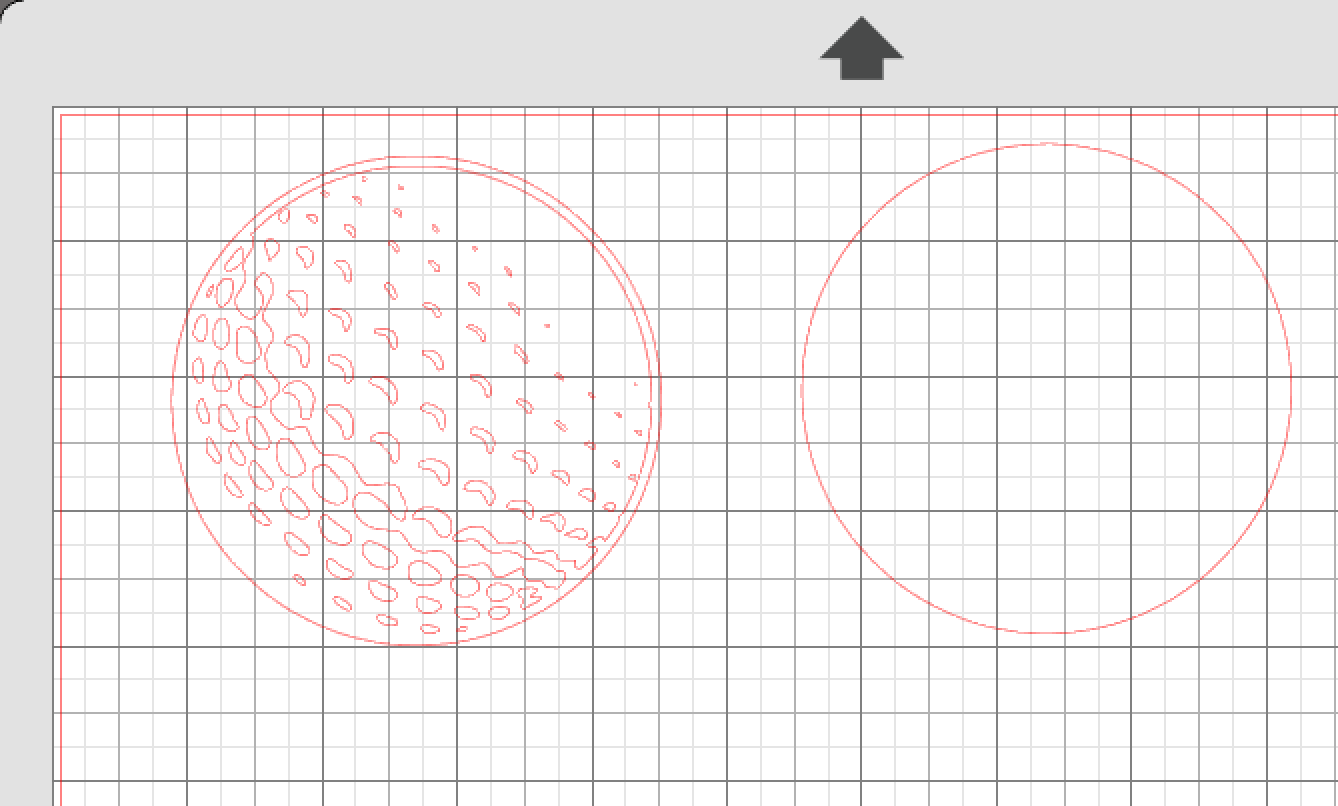
Above is the trace in Silhouette after I traced the seperate layers. The right side is the bottom layer and will be one color. The left is the top layer and adds the detail and contrast. I am going to cut the sticker using 2 differnt colors to add detail and go into increased depth into the task.
Above is my completed sticker after having used the subtractive process of cutting out the 2 layers of my sticker on the vinyl cutter. I sent both parts of my cut file to the sticker cutter. I cut out 2 pieces of vinyl, 1 silver for the bottom layer and one white for the top layer. After the sticker cutter finished cutting, I unloaded the cut mat and began weeding out the pieces on each layer that I did not want. Once I had both sticker cleaned up, I used transfer tape to layer the top layer (white) on top of the bottom silver layer. Finally, I applied more transfer tape and put the completed sticker in the dimple I created for it on my final project.
Working
The video above shows the electronics networked and the motor board reading the sensor values and powering the motor based upon the code I wrote. As shown, when the code hits a trigger value, it shows an A value in the serial monitor becuase I told it to in the code. I identified on values with A and off values with B. These electronics make up all the electronics I am going to use in my final project.
This video above shows the functionality of the motor when connected to a 9 volt battery. Not only does this prove that my sensors and boards work, but also my code. When the golf ball is placed inside the hole, the sensor sends a signal over serial to turn on the motor. As you can see in this video, my cable Management is very poor. I am correcting this in the new board iteration. Another problem is the golf ball sticking out. I am correcting this as well in the new CAD file by making the walls and compartment taller. This was a good first test in my opinion.
Assembly
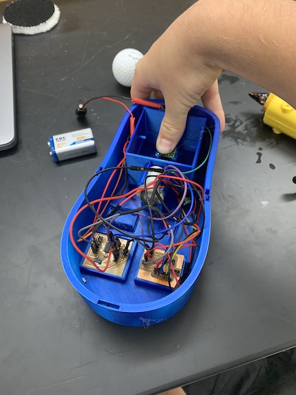
As seen during the Electronics portion of my final project page, the first step was to assemble all of my final project electronics. This included connected my sensor to the input board and then creating splitter jumper cables that connected to my motor power board. Once I had electronics created it became time to assemble all of my cables adn electronics within the case that I created. A problem I encountered while assembling was lack of space to cable manage. I created fletcher fit casings for both the motor and battery within my case to aid but overall had little room to wire manage. Below is an image of my electronics within the case itself before I attach the brushes and complete final assembly.
Above is a video of me sliding in my motor into the fletcher fit case that I created in fusion. I had to test a couple differnt versions to get the correct fitment but afterwords it served the purpose exaclty as I wanted. Through various testing, the motor spun with nom hindrances caused by the case. Now it is time to add in the rest of the electronics.
Above is a videeo of the motor functionality being tested while it is inserted in the mount within the case. This test is also verifying that my electronics work with the new regualator while being powered with a 9 volt instead of a 5 volt USB. I also had to make sure that since I split the power from the 9 volt, that I hadent lost enough current to lose motor power.
Brush Assembly
For the cleaning aspect of my product, I initially wanted to use a gear system. After speaking with Neil and running a series of tests, I decided to not use gears and rather have 1 brush in motion and 3 other stationary brushes. I ordered a set of car detailing brushes that I trimmed along with velcro to be my brushes. The velcro provided a coarser clean then the brushes and overall I am hoping will provide a great clean. In fusion, I created disks that would be placed on pegs to hold the brushes that I cut out. I 3D printed each disc and press fit them on to the pegs.
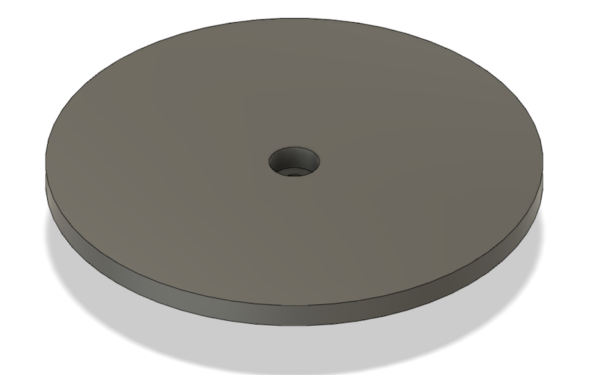
The image above is the fusion file of the disks I made to support the cleaning brushes. I first got the diameter of the motor spindle that I was using. Then I created an offset circle 2 millimeters away and extruded the cylinder. Finally I added the disk on top of the peg that would slot over the motor spindle. I then sliced these prints and printed 2 of them. They each took about 9 minutes which was not that bad. Then I used them as a refrence when I cut out the portion of velcro and brush I was using to clean the golf ball. Finally it was time to assemble.
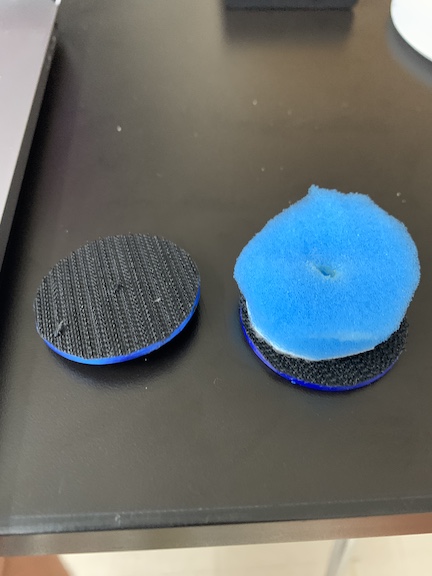
The image above is the completed cleaning brush system. As you can see, the brush on the right side of the picture is much more soft and fluffy. I used this type to provide a smooth clean contrary to the coarse velcro brush on the left side. I used the sticker like back on the velcro to attach it onto the disk and then trimmed up the outside edges. I used a soldering iron to make holes for the pegs in the velcro then attached them to the cleaning product. It is now time to assemble the electronics to finish off my final project for Fab Academy.
Electronics assembly and routing
Using my new mega board which was a combination of both my input and output board. I was able to limit that ammount of jumper cables I needed due to the traces I created on the schematic. Once I milled out the board, I connected each trace/pin with the corresponding pin on either the battery pack or sensor. I had created traces for the RX TX lines as well as for the motor driver board. The battery pack had to feed into the first pins on the output processor to step down the voltage. Once done, the voltage was dispersed across the other micro controllers. Below is an image of all my electronics connected.
Once the electronics where tested and I was assured that they would work as they should, I insterted them into the case that I had previously printed. I started by orienting the double A battery pack in the mount I had printed for it so that I could easily route the power and ground up into my PCB. Next I began connecting elements of my mega board while the battery pack was switched off. I connected power and ground of the entire board to the battery pack and routed the cables up from the pack into the pins. Next, I connected the sensor from its slot and routed the cables through the hole I created so that it was neatly stashed beneath all the components. Next I connected the motor to the breakout pins from the motor driver board. In order to neatly route the cables from the motor, I stripped down the ends and shorted the cables for easier routing. Below is an image of all of my final electroncis assembled and mounted in the case as I want them. In future designs, I want to create a mount for the mega PCB to further better my wire management.
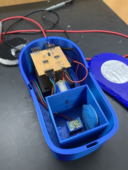
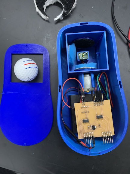
Both images above are two differnt angles to my final wire management and Electronics assembly. The second image shows the top portion of the case as well.
When it was time to assemble the brushes for my final project. I used the disks I had printed earlier. Instead of using 4 brushes, I ended up using jsut the 1 spinning as with multiple, the golf ball would not spin and the motor would not move. I attached the brush bits onto the velcro disks from earlier for cleaning and then trimmed up the brushes. Below is a video of the bursh assembly cleaning the golf ball with just the velcro. As you can see it spins very fast but does not grab the golf ball. Also, the sensor functionality is demonstrated in the video as it turns on only when the golf ball is inserted, however this was with the faulty driver chip before I swapped them out so when the golf ball is removed, the motor does not power down.
Final Assembly
Once I had all the electronics sorted inside the case, it was time to test final assembly. I cleaned up the case and shut the lid, enclosing the Electronics within. I also used the velcro connection to place the brush I was going to use on the velro spinning disk. By this point, I had swapped out the faulty driver boards for the new driver board that finally gave me perfect functionality. The video below displays the golf ball cleaner in action when the golf ball is inserted, it turns on begining the cleaning process. As you can see in the video, the golf ball is spun by the brush as intended. As I had no access to mud, I simulated it by using dried marker on the golf ball. After a brief run period, I remove the golf ball and reveal the success my machine had while cleaning. Once the ball is removed, the motor turns off as intended by my code. I am very happy with the results but ultimately in the futre want to implicate the ability to have the motor stop after a set time so the golf ball can be removed while it is not spinning.
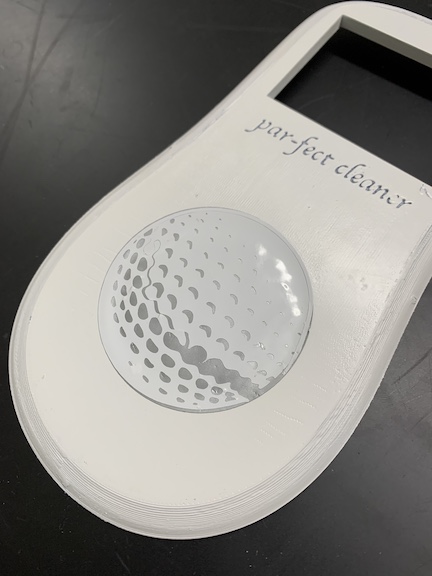
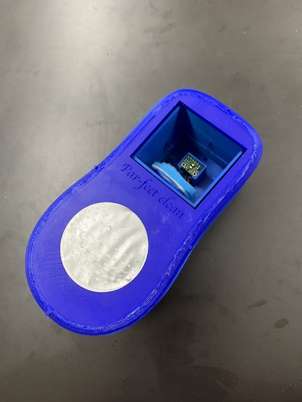
Below are two more images of the final projcet assembled. The final project features the additive process of 3D printing both the top and bottom portion of the case. The bottom half has motor mounts, board mounts, golf ball cleaning compartments and slots. The top portion features pegs to nest with the bottom half of the case as well as a window to insert the golf ball, some branding text, and a circular divit for a vinyl sticker I created. You can see from the picture the cleaning brush on its pad. What you cannot see however is the motor spinning it or the rest of the electroncis other then the sensor which are hidden away.

Materials
| Part | Price Quantity | Purchase |
|---|---|---|
| PCB Boards | $0.69 x1 | In Lab |
| Tiny1614 | $0.71 x2 | In Lab |
| VL53L1X | $9.51 x1 | Pololu |
| Jumper Wires | $5.99 x15 | In Lab |
| DC Motor | $7.49 x1 | In Lab |
| Prushament PLA | $55.00 x1 | In Lab |
| 1UF Capacitor | $0.48 x2 | In Lab |
| 9V Battery | $2.06 x2 | In Lab |
| Surface Headers | $16.74 x27 | In Lab |
| DVR8838 | $3.49 x1 | In Lab |
| FTDI Chip | $15.60 x1 | In Lab |
| Brush set | $13.75 x1 | In Lab |
| Total Cost | $134.01 |
Errors
An error that I enocuntered ocured while I was testing my electronics for my golf ball cleaner. In my code I have an enable and a phase pin on the motor driver board. While testing I relized my sensor was not working correctly as it related to the motor. I first used a multimeeter to double check voltage as well as connections. After I relized I had no bridges, I switched the phase and enable pins. I relised since I had them switched, that when the sensor should be turning the motor on, instead the motor was just changing directions. I resolved this issue by switching the pins correctly.
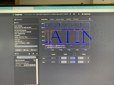
Above is the octoprint user interface. Octoprint allows me to configure and print files to our labs print farm over our schools network. I encountered an error whiile setting up one of our labs Prusa 3D printers. I accidentally had the tempreture set too low causing the printer to underextrude. The correct temperature settings are supposed to be 225 at the tip and 60 on the bed. This resulted in a large time waste that I ended up correcting. Although this was a setback, I corrected my mistake and the new file came out great.
Above is another error I encountered while assembling my final project. I discovered that the 9 volt battery was being destroyed in its attempts to power 2 processors and a DC motor. I went through 4 9 volts before changing my approach. Now I am re designing my file to use 4 double A batteries that provide more current for the motor. Not only will the new solution power the motor better, it will also increase the longevity of my project as well as simplify wire routing.
Another error that I encountered while assembling and testing my electroncis occured with my motor driver board. For some unknown reason, the driver baord was only outputting my motor with 3 volts of power which was not enough to even turn on the motor despite the sensor running as expected. Another problem was that I had no new driver baords to replace this board. What I ended up doing was created a new driver board in eagle with the 10 pin DIL chip and a mosfet. This allowed me to control the motor similar to the old motor driver board. I milled two of these boards and then soldered diodes to prevent flyback voltage from frying all of my electronics. Once these where complete, I tested them with my electronics. These also failed adn resulted in the processor alerting that it was constantly needing to be powered. This caused my motor to nonstop run. Ultimatly I found the solution in using a new driver board. This new board ran smoothly and eleminated all problems I previously had encountered.
Summary
In conclusion to Fab Academy and finishing my personal project, I am very glad I did it and exponentially expanded my engineering Knowledge. Coming into the program, I was deeply hesitant due to the workload that was prommised. Although the work was very heavy and grueling at somepoints, overall my engineering mindset grew adn my skills grew in ways I never imagined. Prior to this program, I could barley solder a surface mount component let alone a processor. I also could never design an Eagle schematic. Both of which are things i now do with ease. My final projcet really allowed me to express mastery in each skilset of mine including CAD softwares and programming. I am very happy with my growth and how is transmitted into my final project.
Futre Plans
Although I have a finished product, I still have things I would change if time permitted. I would like to better open up the compartment were the golf ball is cleaned to allow for more brushes to clean more surfaces. I would also like to purchase a motor with more torque as this problem was encountered numerous times were the motor would not spin due to too much pressure from the ball. I would also like to better mount my PCB. Finally, I think CAD work could have been imporved cleaning up the edges, making it more ergonomic as well as portable. I even would like to add a window for the golf ball to keep it inside as well as a code that stops the cleaning process after a set time to make removal easier. All in all, I am satisfied with my end results but these are possibly ideas for a second iteraton.