12. Output devices
Group Work
For this weeks group work assigment, our group was designated with the task of measuring the measuring the power consumption of an output device. Each group member in the group had to use a oscilloscope to measure the power consumption of a servo as we moved it in differnt positions. A link to all group work completed can be found on the group site here.
Task
The assignment for this week was to add an output device to a microcontroller board you’ve designed, and program it to do something. For this I am going to create a schematic for a board that will spin my motor that I will use in my golf ball cleaner. I will do this through the use of a Tiny1614 proccesor which is going to be communicating with a motor driver board that will then be powering and controlling the motor.
Eagle design
For this week I needed to create a board that would have an output. For my final project I needed a motor to clean the golf ball so for this week I decided to have my output be a motor. In order to power the motor I realized that I needed Driver boards. A board that was recommended to me was the DRV883x Driver Board by Pololu. Before I could begin creating a schematic in eagle for my breakout board I first needed to decide on a processor to use as well as reference the pinout for both to create my schematic. I decided I would use a 1614 processor for this breakout board as it provided all the necessary pins I needed to connect. As for the Driver board I referenced the Data sheet found here. The benefits of this driver board is that it allows me to power brushed and brushless motors from 1V to 11V covering a wide range while also having access to pulse width modulation to control specific speed of the set motor I will be using.

Above is the pinout for the 1614 processor that I will be using to complete my output board for this week’s assignment. This board allows me to access a wider range of pins then there 1614 and after input week I have gained experience using it.

This image above is the pinout for the driver board that I will be using for my output board. It has pins for the power of the board, power of the motor (which are 2 different values), ground, pulse width modulation to control speed and more. I referenced this pinout when creating the schematic for my output board.
Schematic
For my eagle schematic I first had to decide upon a processor I wanted to use. Due to my experience during input week with a 1614 I decided to also use a 1614 for output week. I downloaded the components from the Fab.new library and added them to my schematic. In the eagle schematic view, orientation doesn’t matter as it is changed when I convert the schematic to a board file. Once I added my chip I then imported 2 sets of headers, one to program my board using an Arduino Uno featuring UPDI and another to connect my breakout board to. I then had to route the components so that I could program my board correctly. I connected the power ground and UPDI of the programming headers to the corresponding pins on the processor. Then I referenced the pinout to properly route the pins from my processor to the pins of the breakout board that I would connect. After doing some research I decided I needed to connect power, ground, PWM (which is a pulse width modulation pin allowing me to set the certain speed of the motor), as well as a GPIO pin. In order to power the I needed to connect the ground to the common ground and create a new pin for the motor power (out2) as it required more voltage than the arduino could provide. I ended up connecting this to an external power supply. After my schematic was completed I transferred it to a board file.

Above is an image of my completed schematic. I also had to add a capacitor component connecting my power and ground pin of my 1614 processor to smooth out current flow. I had to manually route each trace in order to make it neat and readable. Orientation doesn’t matter in the schematic so long as everything I needed connected was. I would re orient and rout in the board file, the schematic only establishes which connections are required in the final board file.
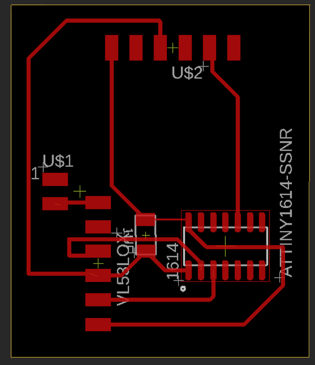
Above is an image of my .brd file after I manually routed each component and oriented it how I wanted. When the file was first transferred from the schematic, none of the traces were connected but there were little yellow lines indicating where I needed connections. These lines were in complete disarray when I first opened the file so the first step I tool was orienting the components in a way that made these lines as organized as possible in order to make milling and soldering as well as routing easier. After I organized each component I first attempted to route using the Autorouter but this was not a success as it formed a lot of close knit traces that would have been difficult to solder. Ultimately I ended up manually routing each component in order to create traces that I liked. Once this was finished I had to change the trace clearance from 6mm which is the default and is very small to 16mm which is what I have used in the past. Finally I saved the file to my drive before beginning to mill it out on the CNC.
Milling process
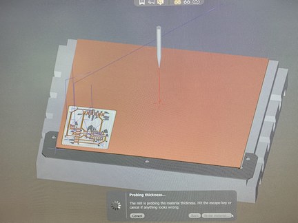
When it came time to mill my schematic that I created, I first had to open my board file on the CNC machine. I positioned it where I wanted it on the material that I was using which was a single sided copper PCB board. I then had to select the first tool I was going to use which in my case was the 15 degree fluted stub bit which I was using for engraving. Then I had to locate the tool. The CNC does this step on its own. Once the tool was located I had to probe the material thickness. This is done by electrically connecting the bed and probing its thickness. I encountered an error here where the machine either registered incorrect values or did not probe at all. I attempted to troubleshoot this error by restarting the machine and the computer as well as exiting and re opening my file. None of these solutions worked and till this day they still have not yet been fixed. I worked around this error by using a caliper to measure the PCB thickness then adding an offset value for the width of the tape. I was finally ready to mill. I decided last minute to create an offset on my traces to allow for easier soldering. This is done by setting a trace clearance then adding the Fab 1/32 bit to mill extra copper. All I needed to do for this is switch the bits after the engraving is completed. While milling the engraving bit worked but when it came to the 1/32 bit the values I imported caused it to mill to deap. This ultimately made my board have lots of copper burs in it. Although it looked messy, I was able to clean it up nicely and make it end up working. I rinsed the board off then scraped excess copper with an exacto blade.
Above is an image of the rendering of the toolpaths for my schematic. I ultimately set the trace clearance much lower from 20mm to 2mm to save more time in the milling process. Above is the result of the 1/32 end mill bit milling away excess copper and can be found in the bantam tools menu under advanced settings.
Soldering
When it came time to solder my completed board I was unsure it would work due to the subpar mill that was a result of incorrect material depth. I first referenced my schematic to see which was to orient the processor. I was starting with the inside components to prevent clustering. Once I knew which way the processor needed to line up, I taped it down. In order to find each component I searched our labs inventory in a spreadsheet provided to us. I applied flux to my board and then began soldering the processor. I first tacked down one corner and lined it up. Then I soldered the opposite corner. Once I was assured it was in line I soldered the remaining pins making no bridges. After the processor was complete I began with the rest of the components. For this schematic I needed 2 sets of 6x1 headers and a 1uf capacitor. I then soldered the capacitor with no problems. Finally I soldered the headers. Once this was completed, I was ready to program.

Above is an image of my completed output board. As you can kind of see from the image, the traces are still not clean cut but they did not cause any problems. Next I am going to connect my board and begin attempting to program it to complete the assignment.
Motor
An important note is that the motor I was using was a hobby 9V DC motor. On the motor driver board I had to connect the motor pins to out1 and out2. These pins received power from the power supply I connected to the VIN power pin on my schematic. I needed the power supply as the arduino is not capable of more than 5 volts. The motor shared a common ground with the board ground.

Driver Board
The Driver board I am using in order to control my motor for this week is a Pololu Drv883x. This board features an H bridge allowing me to control a single Brushed DC motor. This board is also capable of handling 1-11 volts to power motors. It is a breakout board that has pins for powering and grounding the board itself as well as Pulse width modulation for motor speed, Phase pins for direction, a shared ground for the motor and a separate power to power the motor. The motor itself is connected to pins Out1 and Out2. There is no set charge to these pins as the current direction is interchange on the motor I used. Below is an image of the driver board all connected. Although it is hard to see, each pin is labeled making connecting the wires easy and testing with a multimeter.

Coding
When it came time to code my board, I decided to use an Arduino Uno programmed with Jtag2UPDI. I first had to upload the UPDI programmer to the arduino. I compiled and uploaded the sketch without an issue. I set the board to Arduino UNO, the programmer to Arduino as ISP, and the correct port. Once I had the arduino, I connected each cable to the board I created including power ground and UPDI. I then uploaded a code that a classmate of mine created to see whether or not my board was working. I first had to change the board to Tiny1614 and make the programer Jtag2UPDI. Once this was complete, I uploaded using programmer and was surprised that it uploaded first try. I then connected my breakout board to the board I created and the motor to that. I then had to connect the power supply to the driver board. Unfortunately, the motor did not spin. I troubleshooted this by testing each connection with a multimeter and realized the out1 and 2 pins were not getting power but everything else was. I summed this up to a faulty board. I swapped it out with a new one and it worked and the motor spun.
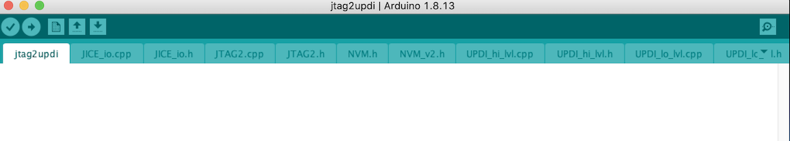
Above is an image of what the Jtag2UPDI sketch looks like when correctly opened in arduino’s software. I then uploaded this to my UNO so that I could use it as a programmer to upload the code to my Tiny1614.

Above is all of my components correctly connected to one another. I had the power supply attached to the driver board motor power and ground pin. Although it would appear like the power supply is bypassing the processor, it is not. The motor is connected to separate pins out1 and 2 which are turned on via the code. In the code I had to make some adjustments to what I wanted it to do with the motor. I also had to change my Phase and PWM pins. I set these to the pins 1 and 0 which they were. I chose these pins because they have the tilda which means they are compatible with the purpose these pins needed to serve.
Code Example
const int pwmpin = 1;
const int phasepin = 0;
void setup()
{
 pinMode(pwmpin, OUTPUT);
 pinMode(phasepin, OUTPUT);
 }

void loop()
 {

 movefwd(255,1); //move function takes analog value then time in seconds (float)

 }


void movefwd(uint8_t spd, float dur)
 {
  digitalWrite(phasepin,HIGH);       //set direction
  analogWrite(pwmpin, spd);      //analog write a PWM value to pin connected to driver
  delay(1000*dur);
  digitalWrite(pwmpin, 0);  //reset analog pin (analog read gives a 10
                                     //bit int, write gives an 8 bit)
 }
Final Video
Above is a video displaying the motor spinning when the power supply is connected to the driver board. I also display the Arduino and my board. I have the power supply close to 9V as this is the recommended power for the motor.
Summary
In conclusion, this week not only made me one step closer to completing my final project, I also was able to learn a lot more about creating my schematic and electronics in general. I completed this week late as I had been behind but ultimately completed the assignment with very minimal errors. I encountered one problem with a faulty driver board but was able to ultimately power the motor through a code on a 1614 processor.