13. Networking and communications
The assignment for this week is to design, build, and connect wired or wireless node(s) with network or bus addresses. I want to incorporate this into my final project by having my input board transmit data about whether or not a golf ball has been inserted and based off that value recived, have my output board spin the motor to clean the ball. I will need to have the input baord transmit data to the output board for this to work.
Group Work
For this weeks group work assigment, our group was designated with the task of using different protocols to communicate between two projects. I aided my group in this task by watching and learning the functionality of software serial. A link to all group work completed can be found on the group site here.
Revisions to Networking week
Following my results from global evaluation, I had to re design a new series of boards to complete the task for the networking electronics week. My previous work did not meet the qualifications as I failed to identify where each signal was coming from and it would of been trivial to use software serial to name the boards as their were only two. To meet the requirements, I first did some reserch about what I needed to complete on my end and then decided to do a master slave board system were when a button was pressed, a 1 would be sent over serial to 2 slave boards. When the 1 was recived, the baords would light up and send a message back over serial stating board a and board b are working depending on which lit up.
Board creation
For this new task I had to create a new board for my new networking ideas and immediatly though of what I used during my interface week. I used a simple blink board that I set up with software serial to blink whenever it recived a 1 over serial sent through processing. I used 2 of these simple blink boards as my slave boards and then had to design a master board. The only requirments I needed for this board was enough pins to have 2 Tx and 2 Rx pins for the software serial as well as power ground and UPDI. I did not use the programmer I created as I only had access to a functional arduino that I programmed JtagUPDI to.
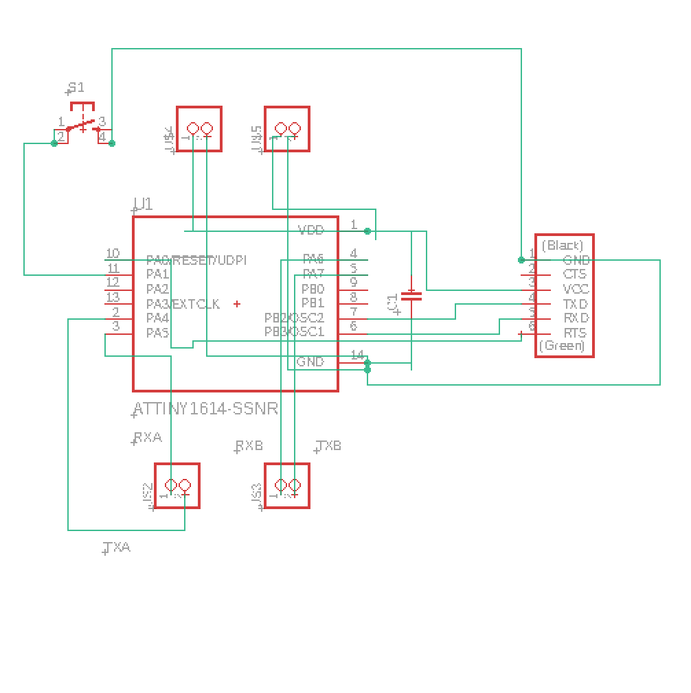
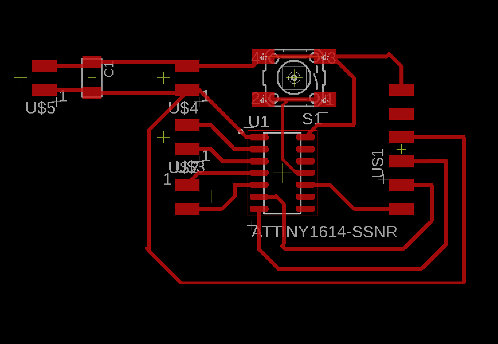
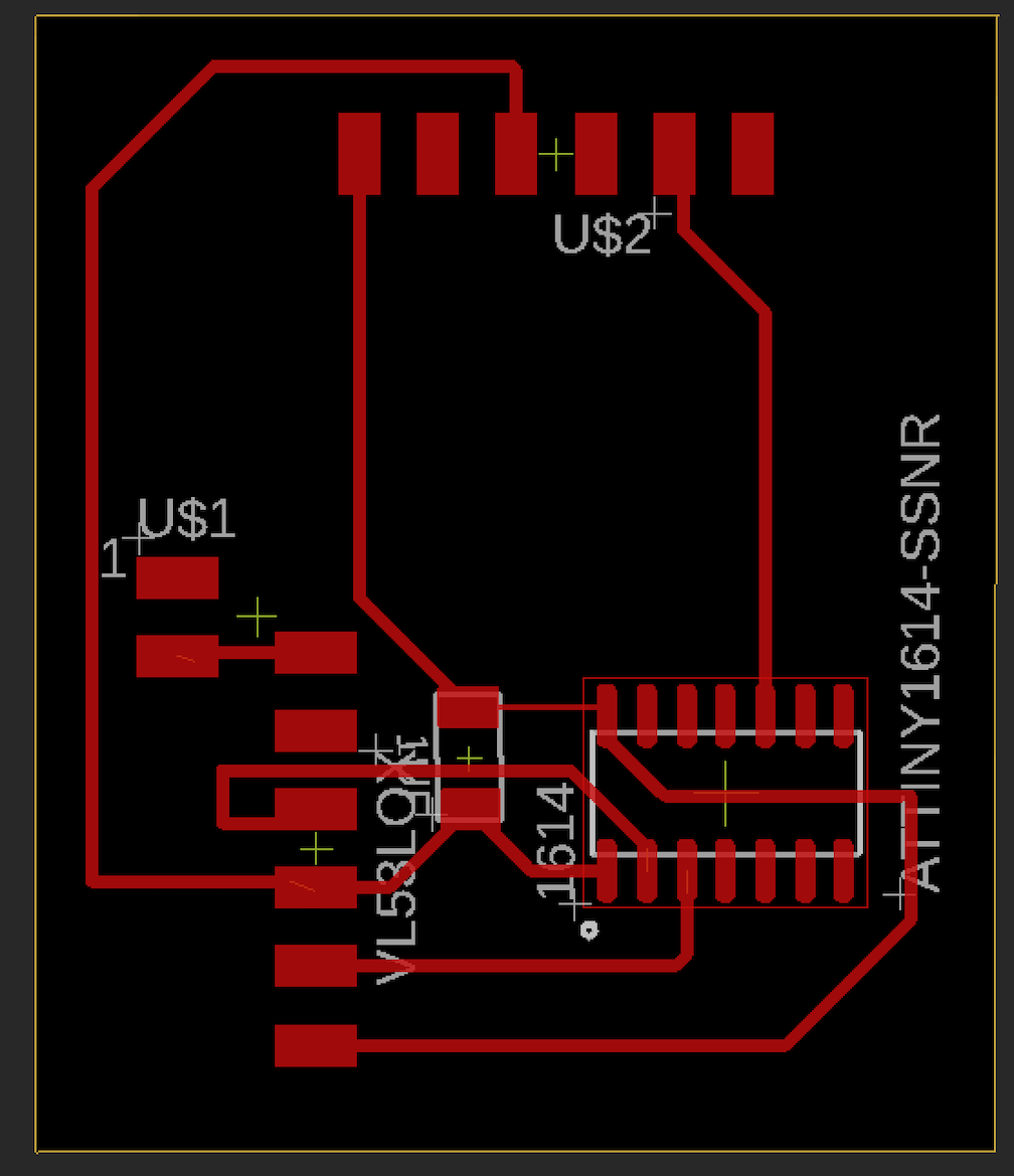
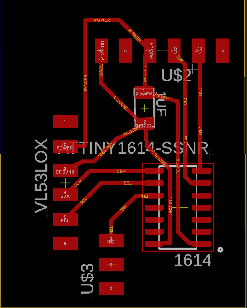
Below is an image of the schematic and board file of my new master board I created in Eagle CAD. I decided to use a 1614 processer as it had enough pins and this would be networked with 2 tiny412 slave boards. I also added enough headers for software serial and a header set for UPDI programming.
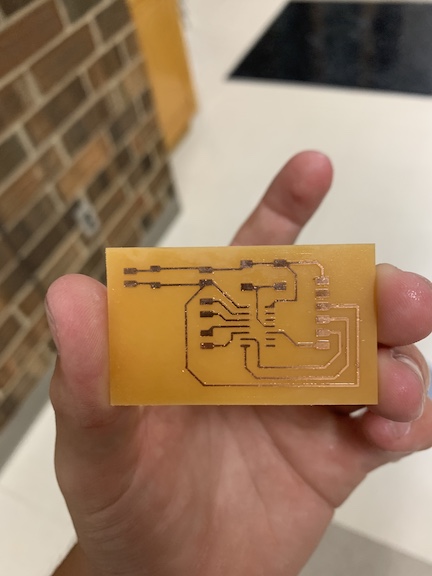
After I created the final schematic for the master board, I saved both of the files and sent them to the schools bantam tools CNC machine to mill out the schematic. For this board, I milled off all the escess copper so that I mitigated the chances of hardware errros and bridges. I used a 15 degree fluted bit for the traces and a 1/32 end mill bit for the excess copper and outline. Once the board was milled, I cleaned it up and began soldering the components.
Below is an image of the master board once I had cleaned it up before I began soldering
Once I finished the soldering process of the all 3 boards, I programmed each of them with the code necessary to complete the networking task. I created a code for each of the slave boards that uses software serial to read if a one is sent by the master board and once that 1 is recived, the board lights up and responds over serial that that board is online.
Below is an example of the code segment
#include <SoftwareSerial.h>

#define RX A1
#define TX A2

SoftwareSerial mySerial(RX, TX);

char val;
int ledPin = 0;

void setup() {

pinMode (ledPin, OUTPUT);
pinMode (RX, INPUT);
pinMode (TX, OUTPUT);
mySerial.begin(9600);
}

void loop() {

if (mySerial.available())
{
  val = mySerial.read();
}
if (val == "1")
{
  digitalWrite(ledPin, HIGH);
  Serial.println("board A is working");
} else
{
  digitalWrite(ledPin, LOW);
}

}
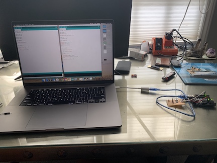
Once I uploaded the 2 slave codes, I had to upload the code I wrote to my master board. This code identifies the 4 pins on the 1614 processor that are being used for software serial as well as sends the 1 over serial causing the 2 blink boards to complete their function. Below is an image of me uploading the code to the master board using an Jtag2UPDI on an Arduino Uno.
Below is the code segment that I uploaded to the master board to complete my task for the networking assignment.
#include <SoftwareSerial.h>
int buttonPin = 8;

#define RXA A5
#define TXA A4

#define RXB A6
#define TXB A7

void setup()
{
  Serial.begin(9600);
}

void loop() {

//if (digitalRead (1) == 1){
if (buttonPin == HIGH){

   // Serial.write("1");
    Serial.println("1");
}
}
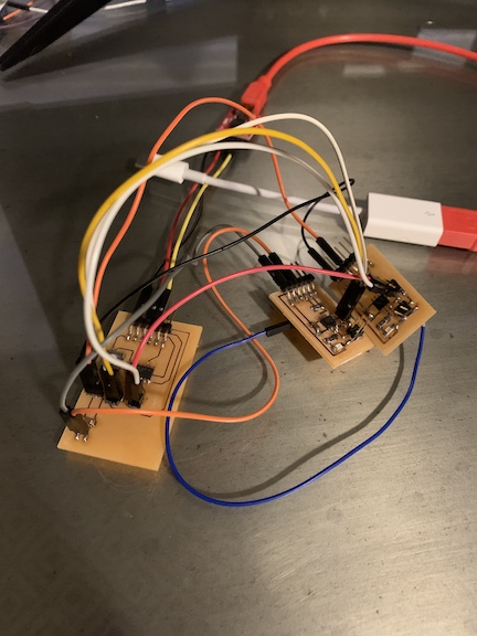
Once I had uploaded all the code to both of the 2 slave boards and my master board, it was time to connect the network of baords to the corresponding TX and RX pins as well as connect the master board to the FTDI chip so I could view the serial monitor. Once everything was connected, I tested the boards for the firt time. When I pressed the button, the LED lit up but did not turn off and I was able to view a 1 over serial constantly without any signal coming back from the slave boards. This tells me that my code is the issue and needs to be revised. I am in the process of revising my code to conclude this task.
Below is an image of the network of the 2 blink boards and 1 master board all connected before I tested using the FTDI chip.\
Boards
The assignment for this week was to network boards that I created. In order to contribute to my final project, I decided to use my input and output boards that I created. This allowed me to have the electronics portion of my final project completed so that when a golf ball is inserted, the time of flight sensor is printing serial data and when the data triggers one of the parameters I wrote in my function, the motor powers up to begin cleaning the golf ball. In order to connect my boards, I had to connect the boards via TXD and RXD to transmit and receive serial data as well as connect both boards to power and share a common ground. I did this by rigging together jumper cables connected to an arduino that I uploaded Jtag2UPDI onto. The schematics for both of these boards can be found on my input week 10 and output week 12 detailing the schematic I created and the data sheet and information for the sensors and breakout boards I used.
Above are the schematics that I used for both my input and output boards. These are the boards I networked and connected the breakout components to in order to make progress towards my completed final project.
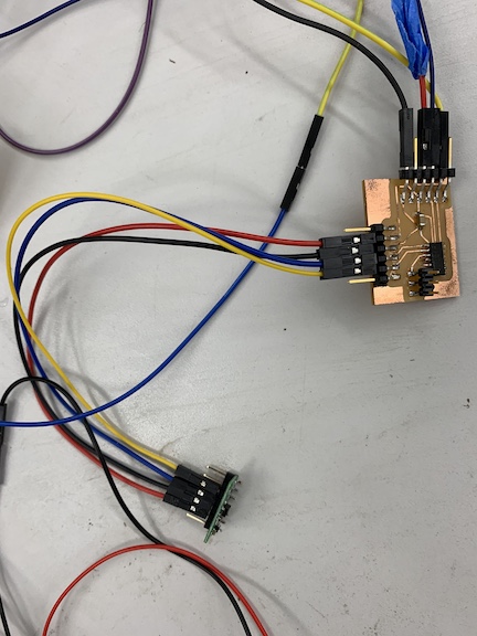
Above is an image of the same sensor board from week 10 that I created and programmed except I am connecting it to the motor driver board via TX and RX pins, a common ground, and power. I am going to combine my code from the IR sensor with the motor driver code and add a loop to allow it to network and function as desired.
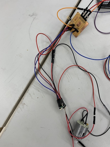
The image above is the same output board from week 12 connected. I have my board that I created connected to my motor driver board connected to a motor. I had to solder a male to female jumper cable to the TX and RX pins of this processor so that it could communicate with the sensor board.
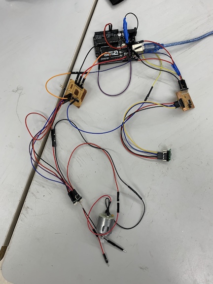
Above is an image of both input and output boards connected to the arduino. I had to connect a common ground and a power between the two boards back to the 5V of the arduino and ground. I also had to connect the UPDI pins to the processors I am coding. I am going to begin creating code to allow these boards to function in sync.
Coding
In order to benign the coding process for this assignment, I first had to connect both my input and output to one another. I had to connect the two processors via the TX and RX pins. This is necessary because in order for the network code to work, the two processors have to communicate with one another based upon the values in the serial monitor. Once I had all my connections correct, I then connected the common power and ground to an Arduino programmed with Jtag2UPDI. Once it became time to write a code for my two boards I separated the input and output code. I needed to upload one code for the IR sensor and then another for the motor that also had the loop to analyze the serial data. I had very little coding experience prior to this so I struggled in making my code actually work although it compiled correctly. My code for the input board was an edited version of the sample code that would only print serial values after having the sensor initialized. I connected the UPDI pin to the arduino and uploaded this code to the input sensor. Then it was time to write the code for the motor board. I first had to paste in the code I used during output week with a couple edits made to it. I changed the motor values of speed and duration to initially off and then when it detects the correct value, fully on. I had to write an if statement in order to analyze the data. This loop contained a function of Serial.ParseInt so that it would print the values, then I used the incoming byte function so that if the serial values are less than or equal to 25 the motor turns on. This signifies when the golf ball has been placed in the cleaner. Once I had this code completed and compiled I disconnected the UPDI from my input board and reconnected the output board UPDI. Then I uploaded the code successfully. Now it is time to test my code and see if it is functional.
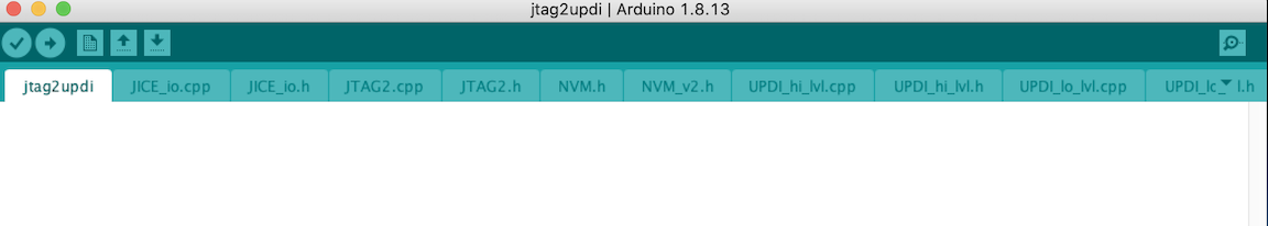
Above is an image of what the Jtag2UPDI sketch looks like when correctly opened in arduino’s software. I then uploaded this to my UNO so that I could use it as a programmer to upload the code to my Tiny1614.
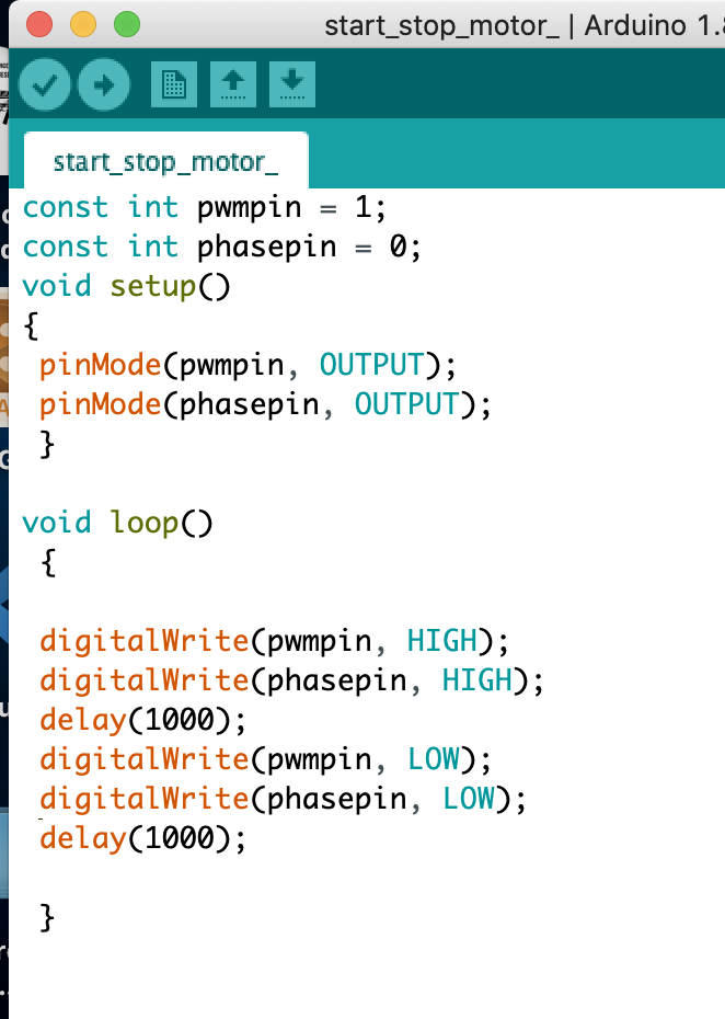
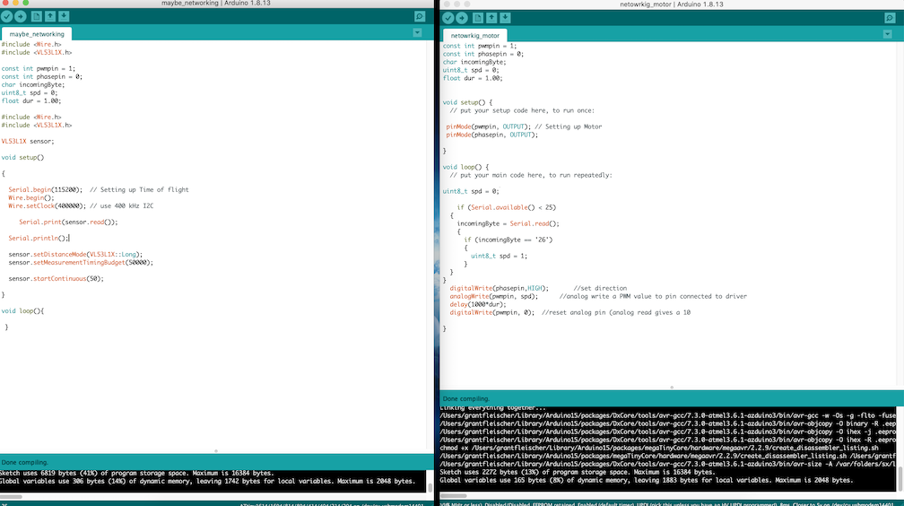
After encountering many errors while attempting to program my motor control board, I tested it by writing a simple code that would turn the motor on and off repeatedly. Above is a screenshot of the segment of code that I wrote.
I also re-wrote the input board code so that each value could be assigned under the variable sensorValue. I edited the code to make this an integer and instead of printing serial.read it printed serial value. I incorporated this variable into my motor board to read the serial data.
#include <Wire.h>
#include <VL53L1X.h>
int sensorValue;


VL53L1X sensor;

void setup()
{
  Serial.begin(115200);
  Wire.begin();
  Wire.setClock(400000); // use 400 kHz I2C

  sensor.setTimeout(500);
  if (!sensor.init())
  {
    Serial.println("Failed to detect and initialize sensor!");
    while (1);
  }

  sensor.setDistanceMode(VL53L1X::Long);
  sensor.setMeasurementTimingBudget(50000);

  sensor.startContinuous(50);
}

void loop()
{

  sensorValue = sensor.read();
  Serial.print(sensorValue);
 // Serial.print(sensor.read());

  if (sensor.timeoutOccurred()) { Serial.print(" TIMEOUT"); }

  Serial.println();
}
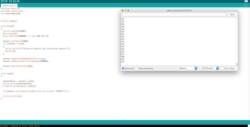
The code segment above is my completed working code that I uploaded to my input board. This code is initializing the library and then setting up the serial read and print statements in the loop so that I can read the data from the sensor about the distance. I know this code works because it worked during my week 10 assignment.
const int pwmpin = 1;
const int phasepin = 0;
int sensorValue = 0;

void setup()
  {
    pinMode(pwmpin, OUTPUT);
    pinMode(phasepin, OUTPUT);
    Serial.begin (115200);
  }

void loop()
 {
    if (Serial.available() > 0) {

  sensorValue = Serial.parseInt();
   delay(10);


  if (sensorValue < 25) {
    digitalWrite(pwmpin, HIGH);
    digitalWrite(phasepin, HIGH);
  Serial.print("A");
  }

  else if (sensorValue >= 25) {
    digitalWrite(pwmpin, LOW);
    digitalWrite(phasepin, LOW);
      Serial.print("B");
  }
Serial.println(sensorValue);

    }//end if serial avail
 }
Above is the code that I used to complete the motor portion. This code not only turns the motor on but also completes the networking aspect of this week’s assignment by reading the sensor values to turn on the motor. This is done by the if statement in the void loop. I also initialized the phase and power pin as well as some other variables. I also had to set speed to 0 and 120 to clean the golf ball. A problem I encountered while attempting to write code for the motor board was not being able to interpret the serial data. In order to troubleshoot this problem, I attempted to write a simple code that printed all serial data the motor received to test if it even worked after a failed attempt of sending the serial values that would trigger the motor via the serial monitor.
Working
The video above shows the electronics networked and the motor board reading the sensor values and powering the motor based upon the code I wrote. As shown, when the code hits a trigger value, it shows an A value in the serial monitor becuase I told it to in the code. I identified on values with A and off values with B. These electronics make up all the electronics I am going to use in my final project.
Summary
In conclusion this week allowed me to learn the most I have learned during my time in the fab academy program. During this week I was met with the most adversity and failure not with my boards but with the code itself. Coding has always been a weak point in my engineering knowledge and this week helped me greatly. Not only was I able to build a networked circuit, I was also able to complete the electronics for my final project. I overall learned the most this week about coding, especially serial reading and transmitting.
Failures
A failure I encountered during this week’s assignment was the processor on my input board was not receiving any power. I used a multi meter and was able to troubleshoot this problem down to just having a bad chip. In order to fix this I reflowed the old processor off and soldering in a new 1614. Another error I encountered was coding. My original code had nothing in the void loop and I quickly realized this would obviously do nothing despite the fact that it was compiling. I quickly fixed this and ensured it would compile. Another error in my code was an error where the input code produced a repeated error that I had the wrong microcontroller. I have not yet corrected this error. Another error was in my serial read area of my motor code. I had serial.Read when it should have been serial.ParseInt in order to act upon the received serial values. I corrected this problem by updating my code then re-uploading.
Above is the code that was wrong where I was lacking many elements. If you look on the left hand side, my void loop for the sensor is completely empty meaning that no matter what I tried and changed, nothing was being done with the sensor. I fixed this by moving the serial read and print into the loop.
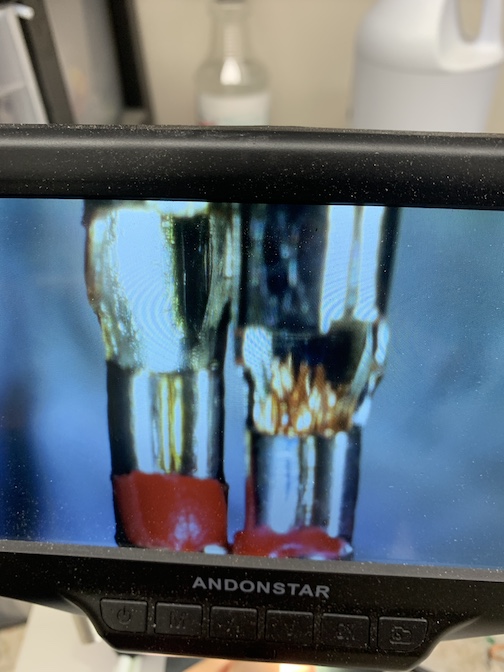
The first image represents a problem that happened that prevented me from being able to power my boards. When I created the jumper cable that allowed the 5 volts to be shared, I accidentally pushed away all the copper creating a charge. As you can see, the image on the right is the problem where no positive current is flowing as the copper was removed whereas the image on the left is still conductive due to the copper.
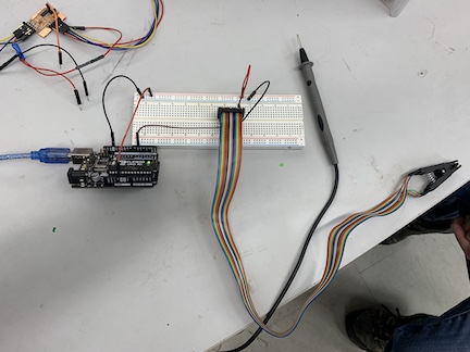
The image above shows me troubleshooting the error from above before I figured out it was a problem with my jumper cables. I attempted to remove all variables from the board by using a clip to directly program the chip and then test it with a breadboard. I ended up stopping halfway through after discovering the jumper cables were the issue.