2. Computer Aided design
Lesson and Assignment
The assignment for this week is to use as many of the different CAD softwares to design projects to develop and understanding and new knowlege. I have chosen to make many small projects in different softwares. Below I have images documenting each of the projects I made in the different softwares. The first image shows a simple dice I made in Tinkercad, a basic CAD software for beginners. I utilized the shapes as well as sizing and push pull tools to create the dice. The second image shows a cookie cutter that I created in fusion 360 that will cut a cookie as well as print the text “mery Xmas”. The 3rd image below is a Corel file to create a tabbed box dice. This displays using the cad software that combines many 2d objects into a 3D object and aided me in my learning about more CAD softwares. The 4th and final image CAD software I used in my exploration was X design. I thought the interface was harder then the rest but I felt as though I learend more. in X Design, I used the canvas tool to insert a refrence image. Then I addded lines and points to outline what would become the base plate for my final RC car. Finally I extruded the base plate to finish it off. I have linked the downloads to all of these images in a google drive folder under the 3D models tap.
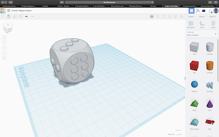
Above is the dice I constructed using TinkerCAD. TinkerCAD is a web based CAD software that is very user friendly. It stores CAD files in the cloud that can be exported and 3D printed. I used tinkerCAD to first learn how to 3D model when I was in the 3rd grade. In TinkerCAD I dragged shapes and was able to group them together to form a simple dice. The major con of this software is its lack of tools. You have to start with pre set figures with very little freedom.
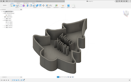
Above is a cookie cutter I constructed in Fusion 360. Fusion 360 is a CAD software as well. While Fusion is harder to learn as a beginer, it is rewarding with many shortcuts for tools and has a great variety of ways to construct 3D files. Fusion offers a variety of functions making it widly used by many. I used the commands such as extrude shell and text to make this cookie cutter a functioning cookie cutter.
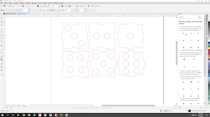
Above is another dice I created using Inkscape. Inkscape is a CAD software that my lab uses for laser cutting. Unlike the other softwares it creates designs in 2D. The major drawback of this software is its lack of tools where softwares like fusion can also export sketches to laser cutters with much more tools. I designed a tabbed box with the different faces of a dice that can be assembled using the tabs on the sides.
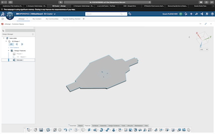
Above is me using a quite different CAD software, xDesign. XDesign is a web based CAD software like tinkerCAD but unlike tinkerCAD it is much less user friendly. I had to learn how to use this software. While the tools do the same the software was quite difficult to use.
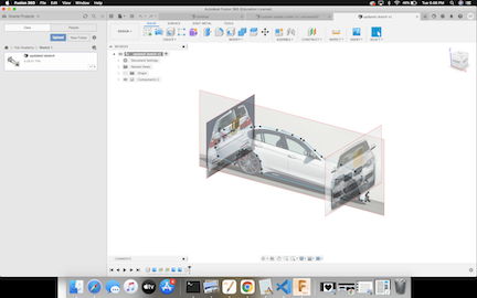
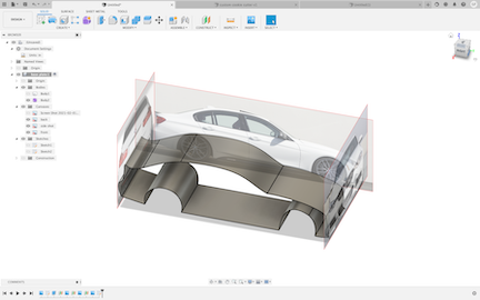
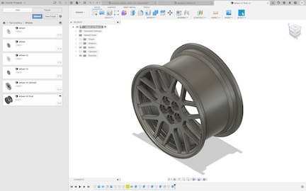
Here is the process as I attempted to use the modeling function on Fusion 360 to create a modeling plane for the shell of my car. I faced an error was that I was unnable to move the edges of the frame and I was only able to select faces despite having the correct settings. The steps included extruding the spline of different profiles of the car. Then positioning the angles, and then filling in the rest of the design by extruding the spline. The first image shows the use of construction planes to organize the faces of the car that will create the body. Image 2 shows extruding half of the car istelf to create the angles that will make up the body. The 3rd Image shows the wheel I created a while back that replicates the BMW ARC-8 wheel. I will use parametric design to re-scale the wheel for my final project.
3D Models
Prior to lesson, building fabricators
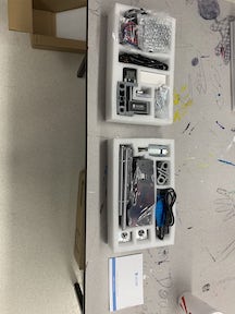
Before beginning this week’s lesson on CAD softwares, my classmates and I assembled our very own personal CNC and 3D printer by Sain Smart. While this wasn’t an extremely complicated process, Some areas of the assembly got complex. Both of the kits we assembled came shipped with everything we needed straight out of the box including tools and screws. While assembling the CNC machine I encountered numerous problems along the way many of which were results from my own human error. I had pieces put in the incorrect orientation as well as motor couplers screwed too tightly restricting motion upon the y axis of my CNC. I quickly addressed all of these problems and then had the CNC back up and running. Our professor had provided us with a document of an example file to run on the CNC to make sure it was up and running. As I am doing my programming on a Mac I ran into some technical issues. I had to download and install and program called candle. This software allowed me to control all axes of the cnc machine through my laptop as well as adding files to be milled and controlling the rotation speed of the spindle. In order to correctly install candle on my laptop I first had to install the Chaser. This would restart my computer and allow me to open the file containing the software I had downloaded. Once I had candle open, I plugged in all my cables connecting my computer to the CNC and the CNC to power I was able to select my ports. To do this I went to preferences and refreshed and it autoselected the correct port for my laptop. Once a connection was established I had full control to change spindle speed and move across all axis.
For the building of the 3D printer I encountered far less problems. I had grown in confidence after creating the CNC and the 3D printer arrived far more pre assembled. While following the directions I had to assemble various components including the axes, motors, and extruder nozzle. While some steps were complex I ultimately succeeded rather quickly in completing my 3D printer. Once I had completed the build It was important to not forget to plug all axes into the correct ports labeled in the instructions. I also had to make sure the PLA ran through the extruder in order to actually be able to print successfully. Finally I would boot up a slicer of my choosing and load a print to test print my 3D printer to confirm everything is running successful. I have not attempted to test print on the printer as of this moment but hope to very shortly prior to the start of CAD week.
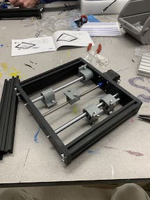
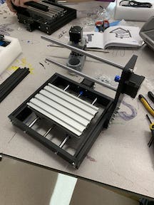
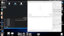
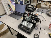
Below are images documenting the process of the building of the CNC kit. The first image represents the unboxing of the kit with all the components. Second image shows the assembly of the base plate followed by the 3rd image of the bed that will hold PCB boards. The 4th image shows the final product with all axis in place and connected to the motor. Image 5 shows candle, the CAD software used to run the machine being setup and finally image 6 shows the CNC all connected to my computer which I used to demonstrate the functionality of the machine. Below is a youtube video showing all my axis and the spindle functioning correctly.
Gallery

Video
From Youtube
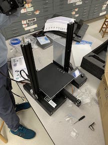
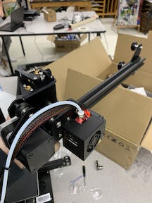
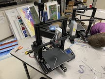
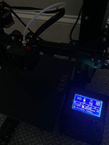
Below are the images of the 3D printer we created. We were each provided our own kit for the 3D printer. I thought it was easier to install then the cnc because it was more assembled out of the box. I have not yet run a program on it but will later this week. The 1st image shows the first step of the assembly process right out of the box. The second photo shows the extruder nozzle which was the second big step. Finally the 3rd image shows the final steps and finished product of the 3d printer turned on.