Revisiting the Project
Research
I was set on this project before we started brainstorming, so this is the only project idea I have.
Through my school’s engineering courses, I decided to revisit my Fab Academy final project. My final project had two major issues- inaccurate movements and a poor method to spin my distance sensor- and I wanted to eliminate these issues through my final project.
Some worries I have with my new proposed project is that the wheels may still not have enough grip to move the car. If this is the case, I would have to increase the weight, but that would also increase the load on the motors, which could cause various problems. I also worry that it may not be able to handle 3D surfaces, even though I am thinking about going into three dimensions. It also may not carry enough power to be able to simultaneously run three boards, a bluetooth chip, and move the car via the stepper motors. I will have to add separate sources of power if this proves to be an issue.
Goals
My two semester goal is to redesign my fab academy final project to a more precise and finished version. I will use stepper motors as the speed and degree of accuracy can be easily implemented and measured. I will also create a system to spin the sensor without tangling wires, and I will try to make it as compact as possible.
This semester, my goal is to complete the electronics design aspects. I may or may not have time to cut out and solder these boards, I will try to fully complete the board that will interact with my distance sensor because my final fab project board can be slightly adjusted to work for two stepper motors. I will also create a rough prototype for the finished car design, including the gear mechanism and organization inside the car.
My fab project was initially inspired partially by the roomba vacuums, which map rooms in order to create efficient cleaning paths, but it was mostly self-inspired as I thought about what I could create.
These are the specific tasks which I will be completing:
- New boards a. Board to communicate and spin sensor b. Board to communicate do BT and move car i. Design done, milling and soldering now
- Fusion designs a. Design main body b. Design sensor mechanism
- Production a. 3d print parts b. Laser cut body
- Assembly
- Cable management
- Programming and testing a. Write code for sensor board b. Write code for main board c. Adjust processing code as needed, or change main code for arduino terminal
- Documentation
- Fab site
This semester, I will be focusing on tasks 1, 2, 3, and 4. I will focus on task 6 over winter break, then improve the physical design aspects in tasks 2-5 next semester.
The main design-specific consideration for my project is size and weight. I am trying to minimize the size, as that would reduce the strain on the motors and improve the look of the product overall. The goal is to reduce the weight as well, but if it is too light it may slip, so that will have to be tested with the final product. For my final product, I will likely layer my components inside the car, as this would drastically reduce surface area.
Materials
Almost all of the materials for my project are in the lab. For my final product, I will use acryllic and plywood that we have in the lab. I will 3D print various components as well. The electronics are fairly cheap, and the most expensive parts are the three 28-BYJ48 Stepper Motors, which are about $1.50 per. I also am reusing my HC-05 bluetooth chip and VL53L1X TOF sensor, which cost about $20 total. I will also order a 7.4V 2500mAh LiPo, which costs about $20. The wood and acryllic for my project costs about $20, and the PLA costs will be about $10. The total for new materials will be a total of $53, and counting the reused parts, the total is $74.50.
Project Management
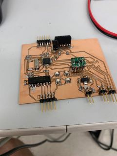
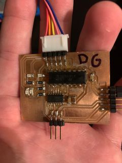
I planned to start with the design and fabrication of my two new boards, as these processes generally take the longest and I didn’t want to save it for last minute. I designed and produced my sensor-spinning board, and designed my second board. I did not fabricate it as I was starting to use a new process, fabricating double sided boards, and I started to eat up the time I would be using for prototyping. Next, I planned to create a general prototype including mounts for sensors, motors, and boards, the car body, and the mechanism to actuate my sensor. I did complete the cad, and finished my prototype just on time after staying in the lab for a few extra hours on the final day.
Tools
I used a variety of tools in the lab. The total list is pcb mills for creating the boards, soldering irons for soldering them, arduino unos for programming them, laser cutters for cutting out the main car body, and 3D printers for creating the mechanical aspects as well as the various mounts.
Daily Journal
My daily journal for the various tasks I preformed can be found here.
Various important decisions and challenges can also be found throughout my daily journal entries, such as the use of bus serial, issues with my fabrication of the second board, and more.
Electronics work
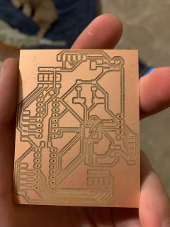
Board One
I started with the movement issue. To fix the movement and make it more accurate, I shifted from dc motors to stepper motors. For this, I needed to make a new board, but I did not have time during the class to create it. I designed the board to be the same as my final project board, but it replace the two DRV motor driver breakout boards with a stepper motor driver board. It took longer than expected to create because I made it two sided due to the large quantity of components on the board. This is the first two sided board I have made. For the time being, I simply removed the two breakout chips and wired the board to a stepper motor driver.
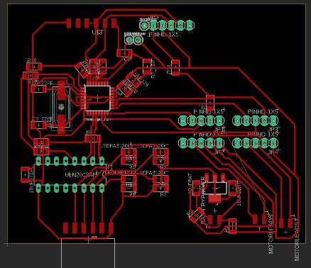
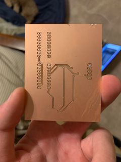
Board Two
Next, I started working on the board that would move the distance sensor. Since I switched to 2 stepper motors for movement, I no longer had enough pins on the 328 to be able to use one board, so I made a new board using an ATTiny1614. This board had communication to my sensor and main board, a stepper motor driver chip, and lines for power and programming.
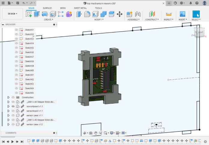
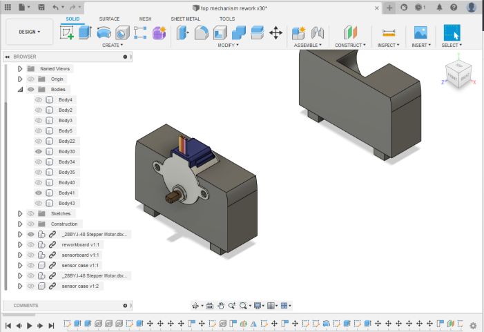
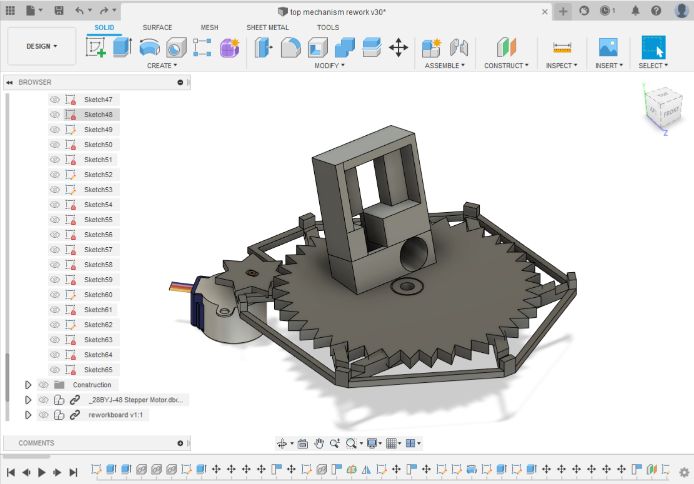
CAD Work
After making and designing the two boards, I started working on the physical aspects. The two boards took longer than I expected, so I did not have a ton of time to work on this part. I created a frame, mounts for my boards and motors, gears for spinning my distance sensor, and space for the battery, charging ports, and programming ports.
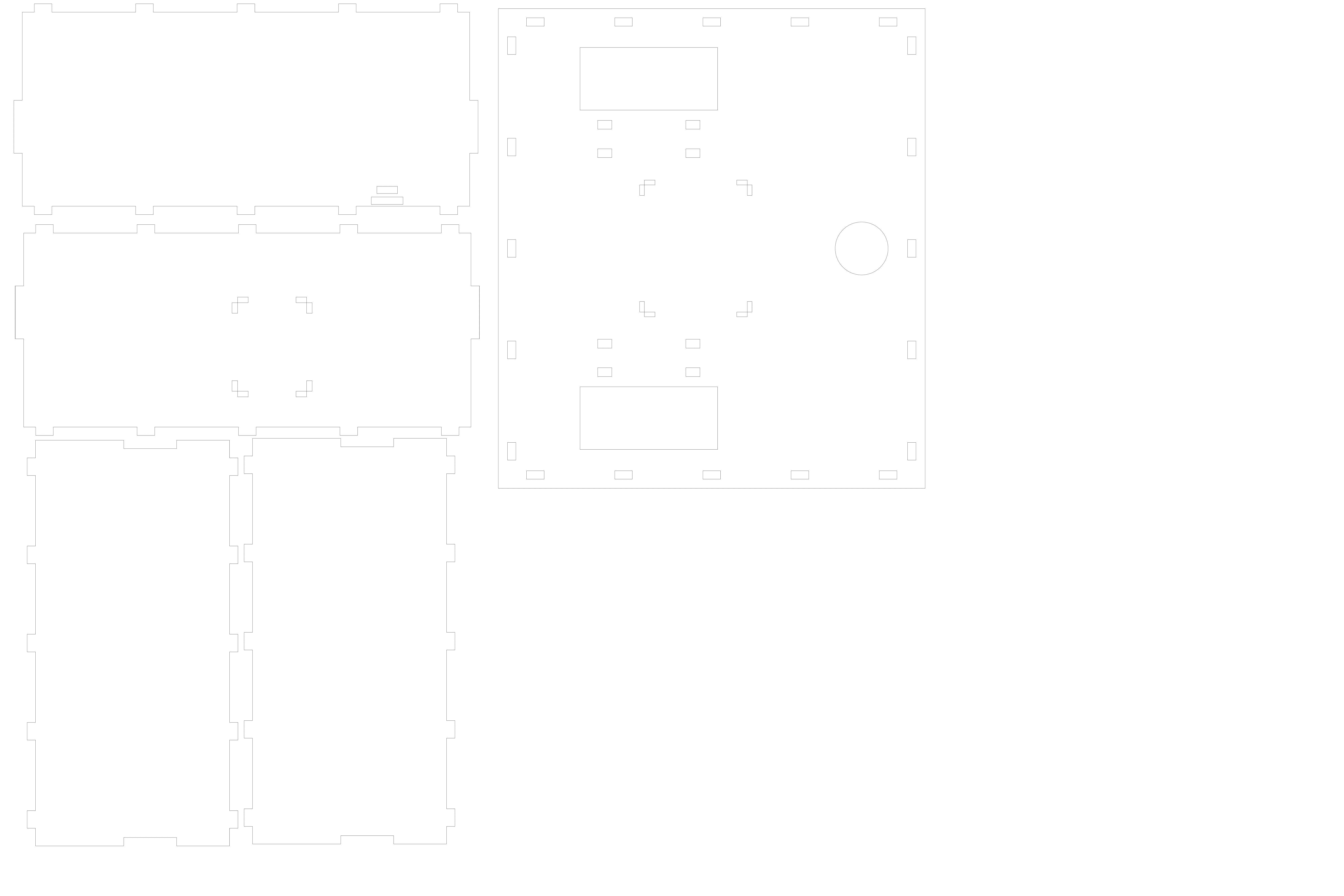

Manufacturing
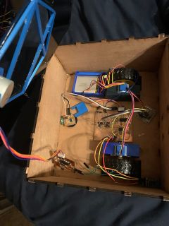
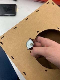
Finally, I began manufacturing the product. I started with cardboard to ensure that everything necessary was included in my cut files, and thankfully, it was working. However, we did not have any 1/8” plywood in the lab, so I quickly changed my joints for 3/16” (which we did have in the lab), tested, and cut it. I cut the sides and bottom of my car out of wood, and the top out of acryllic.
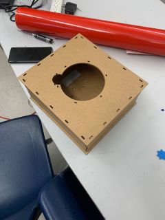
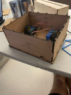
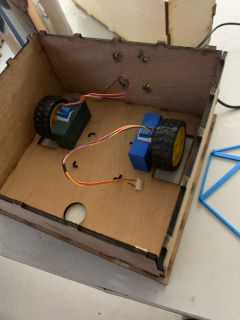
Next, I started working on the 3D prints. These would be used for my motor and board mounts, gears, and some other aspects. I took them from my fusion, printed them in our labs printers, and started assembling them.
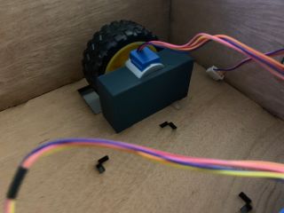
The motor mounts were very successful, and they fit so snugly that I didn’t even have to include screws. The board mount also worked, but my gear mount had some issues, so I reprinted that.
Future Work and Summary
I will be continuing my project during my next semester engineering class, so I will manufacture my second board, clean up the cable management, and create the final design. Over the winter break, I will test my code and look into options for going into three dimensions. If it is feasable for the scope of the class, I will implement it.
Throughout this project, I have improved my general engineering skills and also my project management. I was very close to the deadline for meeting my goals, so in the future I will make a more concrete plan and work more outside of the lab if it is necessary.
Files
My files that I used (except for fusion body files due to their size) can be found in this zip file.
Current Code
Currently, my code is written and works in theory, but I have yet to test it. It is very similar to my previous code, which did work, except for my main board I replaced my dc motors with stepper motors, and I wrote code for a second board with serial and software serial and stepper motor control. The main differneces between this code and my last code was I am changing the arduino side to bus serial, so I have to have tags to designate where the message is supposed to go.
First board code:
For this code, I do not need anything in loop, the car only needs to preform actions when it recognizes a serial signal.
#include <SoftwareSerial.h>
#include <Stepper.h>

#define stepsperrevolution 2048
#define stepangle stepsperrevolution / 360

#define stepper11 2
#define stepper12 8
#define stepper13 7
#define stepper14 4

Stepper stepper1(stepsperrevolution, stepper11, stepper13, stepper12, stepper14);

#define stepper21 11
#define stepper22 12
#define stepper23 10
#define stepper24 13

Stepper stepper2(stepsperrevolution, stepper21, stepper23, stepper22, stepper24);


#define sserial 5
#define sserial2 6


#define wheeldiam 70 //mm


#define spd1 140 //left


float carposx = 0;
float carposy = 0;
float cardeltax = 0;
float cardeltay = 0;
float carangle = 0;
int stepperangle = 0;
bool stepperdir; //false left true right

int indata[28];


int outdata[12][2];

void setup() {

 stepper1.setSpeed(10);
 stepper2.setSpeed(10);
 Serial.begin(9600);

 Serial.setTimeout(10000);


}


void loop() {

}

void serialEvent() {
 Serial.readStringUntil('<');
 String input = Serial.readStringUntil('>');
// Serial.println(input);
if(input.substring(0,1)!="a"){input = ""; return;}
 else{input.remove(0,1);}
 int pointer = 0;
 for(int i = 0; i < input.length(); i++){
  int n = 1;
  if(input.substring(i,i+1) != ","){
    if(input.substring(i,i+1) == ">"){break;}
    while(input.substring(i+n-1,i+n) != "," && input.substring(i+n-1,i+n) != ">"){n++;}
    n--;
    indata[pointer] = input.substring(i,i+n).toInt();
    pointer++;
  }
  i+= n-1;
 }

/* for(int i = 0; i < sizeof(indata)/sizeof(indata[0]); i++){
  Serial.println(indata[i]);
 }
*/
 domove();
}
void moveStraight(int distance, bool dir)
{

 if(dir)
  {
 stepper1.step(distance/22*stepsperrevolution);
 stepper2.step(distance/22*stepsperrevolution);
  }
 else
  {
 stepper1.step(-distance/22*stepsperrevolution);
 stepper2.step(-distance/22*stepsperrevolution);
  }


   cardeltax = cos(3.1415/180*(carangle))*distance;
   cardeltay = sin(3.1415/180*(carangle))*distance;
   carposx += cardeltax;
   carposy += cardeltay;
}

void moveAngle(int angle, bool dir)
{
  int dur = 100*round(angle);
  Serial.print(dur);
   if(dir)
  {
  stepper1.step(1/2*angle);
  stepper2.step(-1/2*angle);
  }
 else
  {
  stepper1.step(-1/2*angle);
  stepper2.step(1/2*angle);
  }
   if(dir){
  carangle += angle;
   }
   else{carangle -= angle;}
}

void mappoints(){
 for(int i = 0; i < 12; i++){
  int ptx = cos(carangle+i*30)*indata[i+1];
  int pty = sin(carangle+i*30)*indata[i+1];
  outdata[i][0] = ptx;
  outdata[i][1] = pty;
 }
 for(int i = 0; i < 28; i++){
  indata[i] == 0;
 }
}

void sendpoints()
{
  String outstring = "<7,";
 for(int i = 0; i < sizeof(outdata) / sizeof(outdata[0]); i++){
  outstring += outdata[i][0];
  outstring += ",";
  outstring += outdata[i][1];
  outstring += ",";
 }
 outstring += ">";
 Serial.println(outstring);
}


void domove()
{

 if(indata[0] == 1){
  moveStraight(indata[1],false);
 }
  else if(indata[0] == 2){
  moveStraight(indata[1],true);
  }
  else if(indata[0] == 3){
  moveAngle(indata[1],false);
  }
  else if(indata[0] == 4){
  moveAngle(indata[1],true);
  }
  else if(indata[0] == 6){

   mappoints();
   sendpoints();
  }
//  else if(indata[0] == 9){
//  scan();
//  sendpoints();
  }
Second Board Code
This code also has nothing in loop, it only responds to serial events.
#include <SoftwareSerial.h> //line to sensor board
#include <Stepper.h>

#define stepsperrevolution 2048
#define stepangle stepsperrevolution/360

#define stepper1 3
#define stepper2 2
#define stepper3 1
#define stepper4 0

SoftwareSerial port2(6 , 7);
Stepper stepper(stepsperrevolution, stepper1,stepper3,stepper2, stepper4);

#define rx 4
#define tx 5

#define sensorrx 6
#define ssplaceholder 7


int indata[8];
int outdata [28];
int stepperangle;

void setup() {
stepper.setSpeed(10);
Serial.begin(9600);
Serial.setTimeout(10000);
port2.begin(1200);

}

void loop() {


}


void serialEvent(){
   Serial.readStringUntil('<');
 String input = Serial.readStringUntil('>');
// Serial.println(input);
 if(input.substring(0,1)!="a"){input="";return;}
 else{input.remove(0,1);}
 int pointer = 0;
 for(int i = 0; i < input.length(); i++){
  int n = 1;
  if(input.substring(i,i+1) != ","){
    if(input.substring(i,i+1) == ">"){break;}
    while(input.substring(i+n-1,i+n) != "," && input.substring(i+n-1,i+n) != ">"){n++;}
    n--;
    indata[pointer] = input.substring(i,i+n).toInt();
    pointer++;
  }
  i+= n-1;
 }
 interpretaction();
}

void interpretaction(){
  if(indata[2] == 2){
    if(indata[0] == 9){
      scan();
    }
  }

  else{
    return;
  }
}

void scan()
{
  int pointer = 0;
  for(int i = 0; i < 360; i += 30){
  stepper.step(30*stepangle);
  stepperangle += 30;
  port2.listen();
  int distance = port2.parseInt();
  outdata[i/30] = distance;
  }

}

void senddata(){
  String message = "<a6,";
  for(int i = 0; i < 12; i++){
    message += outdata[i];
    outdata[i] = 0;
    message += ",";
  }
  message += ">";
  Serial.println(message);
}
Processing
The only differneces between my previous and current processing code is accounting for bus serial by using tags.
import processing.serial.*;

Serial port;


int mainwid = 1300;
int mainheight = 800;

int displaywid = 650;
int displayheight = 650;
int midpointx = displaywid/2+50;
int midpointy = displayheight/2+50;

int controlwid = 400;
int controlheight = 600;

int datawid = 1175;
int datalen = 50;

int[][] pointdata = new int [400][2];
float[][] mappeddata = new float [400][2];
int yoffset = 50 + displayheight / 2;
int xoffset = 50 + displaywid / 2;
float scale = 10;

float carangle = 0;
float carx = 0;
float cary = 0;


int tSx0;
int[] outdata = new int[5];

boolean indir = false;
boolean indir2 = false;

int x;
int angle;
int distance;
int type; //1/2 F/B, 3/4 L/R

int mainboard = 1;
int processing = 3;

void setup()
{
 size (1300,800);   //size
 port = new Serial(this, Serial.list()[1], 9600);
 port.bufferUntil('\n');
 drawSetup();
}


void drawSetup()
{
 fill (125);
 rect (0,0,mainwid,mainheight);   //main area rectangle

 fill (0);
 line (50,50+displayheight/2,displaywid+50,displayheight/2+50); //x axis
 line (50+displaywid/2,50,displaywid/2+50,displayheight+50);    //y axis
 for(int i = 1; i < 8; i++)
 {
   line((midpointx+i*displaywid/2/8),midpointy-5,midpointx+i*displaywid/2/8,midpointy+5);
   line((midpointx-i*displaywid/2/8),midpointy-5,midpointx-i*displaywid/2/8,midpointy+5);
   line(midpointx-5,(midpointy+i*displaywid/2/8),midpointx+5,(midpointy+i*displaywid/2/8));
   line(midpointx-5,(midpointy-i*displaywid/2/8),midpointx+5,(midpointy-i*displaywid/2/8)); //grid
 }
 text((scale/10 + "cm"), midpointx+displaywid/16-5, midpointy+20); //text for scale
 fill (200);
 rect (displaywid+100+75,50,controlwid,controlheight); //controls interface
 fill(250);
 rect (50, mainheight-70,datawid,datalen); //data line
 fill(0);
 text("Car Angle:" + carangle,60, mainheight-50);
 text("Car X Position:" + carx,160, mainheight-50);
 text("Car Y Position:" + cary,290, mainheight-50);

 controlpannelsetup();
}

void controlpannelsetup()
{
 fill(0,128,128);
 rect(855,80,170,170);
 fill(255,180,0);
 rect(855,80,170,50);
 rect(855,200,170,50);
 fill(255,120,0);
 rect(855,130,50,70);
 rect(975,130,50,70);
 fill(0);
 text("forward",910,110);
 text("backward",910,230);
 text("left",872,170);
 text("right",990,170);
 text("scan",930,170);
}


void mousePressed()
{

 delay(100);
 if(mouseX > 855 && mouseY > 80 && mouseX < 855 + 170 && mouseY < 80 + 50){print("forward"); type = 1; move();}
 if(mouseX > 855 && mouseY > 200 && mouseX < 855 + 170 && mouseY < 200 + 50){print("backward"); type = 2; move();}
 if(mouseX > 855 && mouseY > 130 && mouseX < 855 + 50 && mouseY < 130 + 70){print("left"); type = 3; move();}
 if(mouseX > 975 && mouseY > 130 && mouseX < 975 + 50 && mouseY < 130 + 70){print("right"); type = 4;move();}
 if(mouseX > 855 + 50 && mouseY > 80 + 50 && mouseX < 975 && mouseY < 200){
  print("scan");
  String message = "";
  message = "<" + "a" + "9" + "," + "0" + "," + ">";
    print(message);
  port.write(message);

  }        // print here will be replaced with btport print for final code

 if(indir && mouseX > 1050 && mouseX < 1050 + 160 && mouseY > 115 && mouseY < 115 + 30)
 {

   drawSetup();
   controlpannelsetup();

   move();

  fill(0);
  rect(mouseX, 125, 5, 10);

  if(type == 3 || type == 4){
  float fx = map(mouseX, 1050, 1050 + 160, 0, 180);
  x = round(fx);
  angle = x;
  print(angle);
  text("angle: " + x, 1161, 160);
  }

  else if(type == 1 || type == 2)
  {
    float fx = map(mouseX, 1050, 1050 + 160, 0, 100);
    x = round(fx);
    if(type == 2){text("distance: -" + x + "cm", 1161, 160);}
    else if(type == 1){text("distance: " + x + "cm", 1161, 160);}
    distance = x;
  }

  indir2 = true;

 }

 if(indir2 && mouseX > 1100 && mouseY > 150 && mouseX < 1100 + 50 && mouseY < 150 + 50)
 {
   indir = false;
   indir2 = false;
   print("confirm");


   String message = "";

   if(type == 3){
     message =  "<" + "a" + "3" + "," + angle + "," + ">";
     print(message);
   port.write(message);
   }
   else if(type == 4){
   message = "<" + "a" + "4" + "," + angle + "," + ">";
   port.write(message);
   print(message);
   }
   else if(type == 1){
   message = "<" + "a" + "1" + "," + distance + "," + ">";
   port.write(message);
   print(message);
   }
   else if(type == 2){
   message = "<" + "a" + "2" + "," + distance + "," + ">";
   port.write(message);
   print(message);
   }

//prints here will be replaced with btport prints to send the data for movements


  drawSetup();
 }
 if(indir && mouseX > 1050 && mouseY > 150 && mouseX < 1050 + 50 && mouseY < 150 + 50)
 {
   indir = false;
   indir2 = false;
   print("reset");
   drawSetup();
 }


}


 void move()
 {
   indir = true;
   fill(10);
   rect(1050,115,160,30);
   fill(250);
   rect(1050,125,160,10);
   fill(200);
   rect(1110,150,50,50);
   fill(0);
   text("confirm",1115,175);
   fill(200);
   rect(1050,150,50,50);
   fill(0);
   text("reset",1060,175);
   delay(500);

 }


void draw()
{
mapdata();
fill(255);
for(int i = 0; i < mappeddata.length; i++)
{
  if(mappeddata[i][0] == 0){break;}
  rect(mappeddata[i][0],mappeddata[i][1],5,5);
}
delay(1000);


}


void serialEvent(Serial port) {
   port.readStringUntil('<');
   String data = port.readString(); //catch serial data
   print(data);
  try {

    int[] input = int(data.trim().split(",")); //split input string by ,
        for(int i = 0; i < 5; i++){
     println(input[i]);
   }
    if(input[0] == 1)

    {
    for(int i = 1; i < input.length; i+=2){ //for each pos in input data
     for(int j = 0; j < pointdata.length; j++){
      if(pointdata[j][0] == 0){ //check if value at incrementing pointer is set, if set, do nothing and continue, if not set, add more data starting from here
      pointdata[j][0] = input[i];
      pointdata[j][1] = input[i+1];
      break;
      }
    }
   }

  }


  }
  catch(Exception e) { //java do java reeeeeeeeeeeeeeeeeeeeeeeeeeeeeeeeeeeeeeeeeeeeeeeeeeeeeeeeeeeeeeeeeeeeeeee
    e.printStackTrace();
  }
// mapdata();
 //drawpoints();
}


void mapdata()
{
  for(int i = 0; i < pointdata.length; i++)
  {
   float mappedpointx = pointdata[i][0]*1/scale;
   float mappedpointy = pointdata[i][1]*1/scale;
   mappeddata[i][0] = mappedpointx + xoffset;
   mappeddata[i][1] = mappedpointy + yoffset;
  }
/*  for(int i = 0; i < mappeddata.length; i++)
  {
   if((mappeddata[i][0] > displaywid + 50 || mappeddata[i][0] < 50) || (mappeddata[i][1] > displayheight + 50 || mappeddata[i][1] < 50))
  {
   scale *= 2;
  }
 }
 */
}