6. Electronics design
This week my assignment was to redraw an echo hello-world board, add at least a button and LED, check the design rules, make it, and test it. Our group assignment was to use the test equipment in our lab to observe the operation of a microcontroller circuit board.
ATTiny412 Blink Board
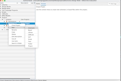
I started the week by designing a simple blink board. I decided to use the software EagleCAD since I had some experience through my electrical engineering class. I started by starting a new project and opening a new schematic.
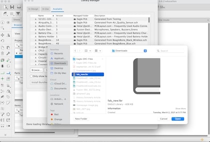
I then downloaded the Fab_New library provided by our teachers and opened it into my project. This library has most of the common components found in our lab, so it will be useful when designing circuits. I also opened a few other libraries, such as the Sparkfun libraries that would have some components that I would use as well.
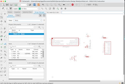
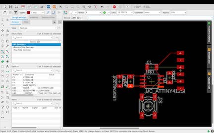
Next, I added all the components that I would need for this assignment. I went to the add part and added a capacitor, a few resistors, an LED, a button, a row of header pins, and of course the ATTiny412 chip. All of the components were located in the Fab_New library, so I added them. I then netted the components together so I can create a board file with the electrical connections laid out.
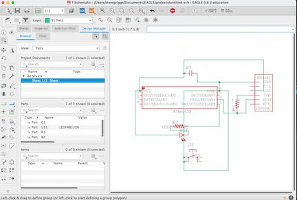
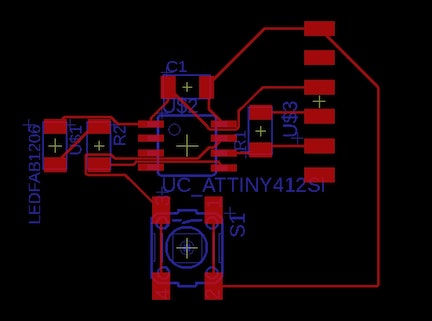
Finally, I created the board file from the schematic by clicking generate/switch to board. I moved the components towards the center, rotated them so that their connections were in the simplest orientation, and routed them together. Finally, I dragged the yellow edge as close as possible towards the board to create an outline for it to cut through.
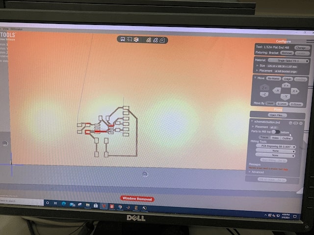
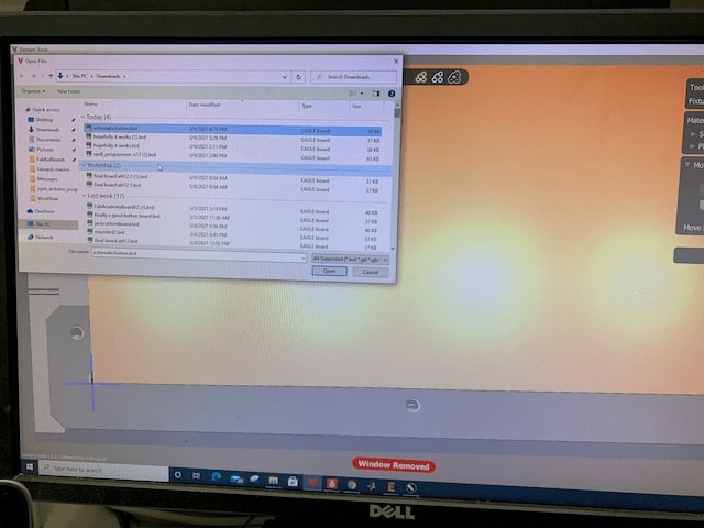
I then uploaded the .brd file to my lab’s PCB mill and milled it out. I used the software Bantamtools with our lab’s othermill CNC machine to mill out the board. I uploaded my .brd file into the software, and the software turned it into gcode.
After milling out the board, I washed and soldered the board:
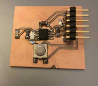
I then borrowed Dr. Harris’ programmer (mine was at home) to upload a simple blink program to the board (using the same process described in electronics production week) to test it, and it worked. I then wrote a short program to change the state of the led after each press, and that worked as well.
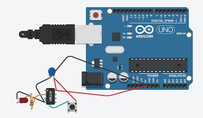
After designing my circuit, I decided to simulate it. I used TinkerCAD to simulate it because it had the ATTiny chip I used. I started by making a new project and adding the components. TinkerCAD is very user-friendly and my circuit is very simple, so it only took me about 5 minutes. I then added an Arduino Uno to power it with 5V and wrote the code to switch the LED state.
bool n=false;
void setup() {
  pinMode(3, OUTPUT);
  pinMode(4,OUTPUT);
  digitalWrite(4, LOW);
}

void loop() {
if(digitalRead(4)==0){
  n=!n;
  if(n){
    digitalWrite(3,HIGH);
  }
  else{
    digitalWrite(3,LOW);
  }
  delay(250);
 }
}
This is the same code that I used to program my LED button board.
The simulation of the board worked, and the button switched the state:
What did I learn?
This week, I learned quite a bit about Autodesk’s Eagle. I had briefly used it with my electrical engineering class, but this week I developed a much deeper understanding of the design process. After dealing with some weak traces, I learned to use thicker traces in the future. I also learned about how to upload libraries in Eagle- before I had only been using the pre-installed libraries, but this week I imported a library that contained some surface-mounted components in our lab.
Group Assignment
Our group assignment was to use our lab equipment to observe the operation of a microcontroller circuit board. My documentation for that assignment can be found on our group site under group assignments and week 4. We used a multimeter and an oscilloscope to observe the operation of microcontrollers.
Final Project Work
With my assignment completely done on the first day of the week, I decided to start thinking about and designing my board for my final project. My final project will be an autonomous car that will map out a room with a distance sensor. I wasn’t entirely sure about what type of distance sensor I wanted to use, but I knew that I wanted to use 4 DC motors to drive my car and a stepper motor to adjust the angle of the distance sensor. I started by looking into the types of DC motors and what was required to control one. I decided to use four DC motors to drive my car since they are small, simple to control, and have fairly high RPM. I will also use a stepper motor similar to the 28byj-48 stepper motor.
I started by designing a board similar to Sashakit. I did not include a couple of the LEDs, but the other components and layouts are the same. Right now, I have all the header pins that were in the original Sashakit, but when I finalize my output and input boards, I will remove all the unnecessary header pins.
After designing my Sashakit board, I designed two motor boards for the stepper motor and 4 DC motors. For the stepper motors, I used the ULN2003A chip. This chip is in the driver board for the stepper motors in our lab, and it is very simple to use. I will use 4 of its 7 inputs, and the chip has 4 output lines as well as a common ground line that will connect to the stepper motor. All I had to do was connect the input lines to 4 port pins on my 328 chip, it doesn’t even need PWM.
The next motor board I made was the one to control my DC motors. I decided to use the L293D chip after looking through a few options for H-Bridge Chips. An H Bridge chip allows me to both 1. control the rpm of a dc motor through PWM, and 2. separate the high voltage and current required for the motors from the microcontroller board. I control the board through 4 input lines that require PWM, and I output the voltage through four output pins. The input voltage needs to be higher than 1/2 the reference voltage (Vss) to produce a logical 1, so I will connect the Vss pin to 9V and the input pins to 5V from the 328 pins. Each pair of output pins connects to one DC motor, so I will be connecting the motors on each side of my car in parallel. I simulated the operation of this board through Tinker Circuits, the circuit diagram looks like this:
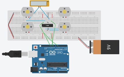
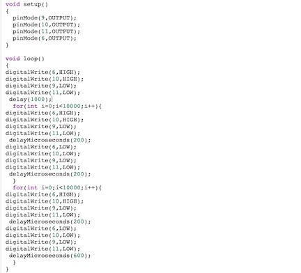
I wrote a few lines of code to help me understand the PWM functions through this board. From what I understand, a constant logical 1 (5V) will result in the DC motor constantly being on, which will max out its RPM. If PWM is used, the RPM of the DC motor will be adjusted according to the ratio of high time to low time. For example, a 1:1 ratio will result in about 1/2 the RPM, while a 1:3 ratio will result in about 1/4 the RPM. I can use PWM to control the speed of each pair of motors on my final car.
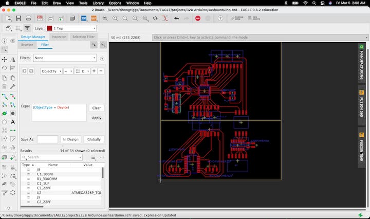
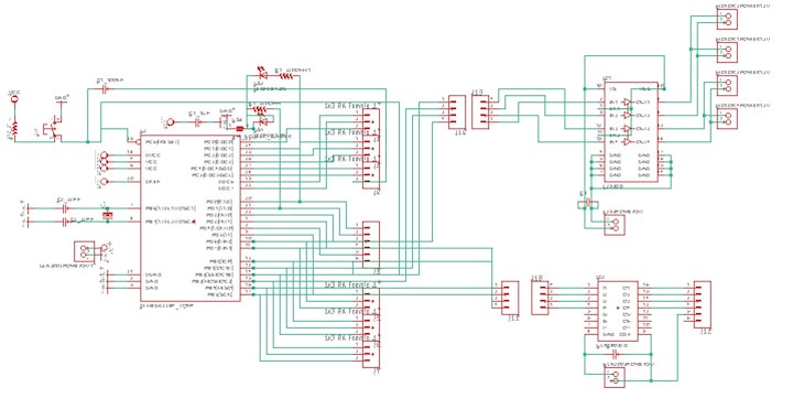
After understanding the pin layout and functions of the two chips, I added each chip into the Sashakit eagle cad file. I added a few components- mostly headers and a few capacitors. I then looked through the pinout of my sashakit and decided to use the PWM pins PD6 and PB1-3 for my L293D board. I decided to use the pins PB4-5, PB0, and PD7 for the stepper motor. The schematic and board diagram up to this point looks like this:
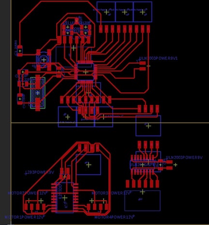
After creating these two boards and creating header pin connections, I decided to add a TX and RD LED to help with debugging, a solder jumper so that I can disable the test LEDs, and I removed a random 0 OHM resistor that I had added earlier when trying to fix my routes. Currently, my board looks like this:
When I finalize my board, I will remove all the unnecessary pin headers. I will also add a voltage regulator to draw the 9V battery down to 5v for the microcontroller board and possibly lower for a sensor board. I will use a 9V battery because I need 9V for most DC motors.
Group Assignment
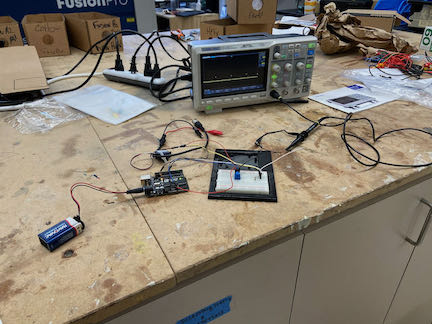
This week’s group assignment was to use the test equipment in your lab to observe the operation of a microcontroller circuit board. My group’s documentation can be found on our lab’s group page.
We used our lab’s SDS1202X-E Oscilloscope to observe the operation of a servo motor through its data wire.
This week’s files can all be found in this zip file.