12. Output devices
This week, I will design the output devices for my final project. My final project’s outputs will consist of 4 brushed geared dc motors and a geared stepper motor, so I will design the boards to control and test my motors.
DC MOTOR
Earlier Work
Since I was ahead during electronics design week, I started looking at possible controllers for my dc motors. I looked into H-bridge chips and designed a board around the L293d. This chip is able to control 2 dc motors but has a major drawback for my project. My project will involve 4 dc motors, so I would connect each side’s motors in parallel to the L293d board.

Unfortunately, the chip can only handle up to .5 amps of current. Each motor I’m using has a stall current draw of 1.5 amps, so this board will not be sufficient.
New Design
I will be using 4 3V-6V gear brushed dc motors from YeeCo electronics on amazon:

I looked through the boards discussed by Neil and decided to go with the DRV883x Low-Voltage H-Bridge Driver from Pololu since my motors are 6V. The DRV chip only had 2 output leads for motors, which can control 2 motors for me in parallel, so I will use 2 of these boards for my final.

I started by designing a breakout board to test with an ATtiny412 chip. My final project’s board will use an ATMega328p, which is much larger and requires more components than the 412, so the 412 will work for testing purposes.
I looked through the datasheet for a breakout board I ordered and lined up the pins to the corresponding pins on my Arduino. It only needs a PWM pin and a regular data pin from my 412 chip, 2 different power/ground leads for the breakout board and motor power, as well as 2 pins for motor output. I also included headers for programming the ATtiny and a capacitor to even the incoming current out, and I created this schematic and board:


Unfortunately, while designing my board, I selected the wrong pin header type, and my vertical pinholes were too far apart for the headers in the lab to fit through.

I then selected the right pin header size and re-milled and soldered my board.


Software
Issues
I wrote some simple code to send PWM waves to one pin and a 1 or 0 to another, but I had some problems. My motor board controls one dc motor through 2 pins- one for direction, and one for speed. The direction needs to be a 0 or 1, while the speed pin can be a 1 or 0 for full power or off, or a pulse width modulation value for any speed between 0 and 1. Unfortunately, my attiny412 board was not giving any PWM output through the speed pin, yet it could give PWM values to the direction pin. I checked for shorts, but there were none. I double-checked the pinout for the attiny412, and it said that pin 4, the pin connected to the speed pin, had PWM capabilities, and that pin 3, the pin connected to direction, was a data pin without PWM capabilities.
I triple-checked my schematic and pinout, but the board was connected correctly. Confused by the problem, I decided to switch the PWM and data pins and remilled. This time, the PWM pin worked but the data pin wasn’t lighting up. I google-searched for problems with PWM on the ATtiny412, but I found none similar to mine.
Frustrated by the problem, I designed and milled a board with 8 headers, the attiny412 chip, and a 1 uf capacitor to regulate current. I used this board to test which pins are capable of PWM and found that the only ones that were capable were pins 2 and 3, the bottom 2 pins. Strangely enough, the pinout does not say that these two pins are PWM capable. It is possible that I messed up something in the software, but I was simply using analogWrite() with the Arduino library, so it is unlikely.

With my newfound knowledge of the attiny412 board, I redesigned my test board around these pins. I connected pins 2 and 3 to the speed and direction headers and milled and soldered again.
I tested it by attaching an LED (with a current limiting resistor) to the speed and direction pins and cycling through a few different types of movements. It worked, and at this point, I was waiting on my electronics to arrive.
const int pwmpin = 3;
const int phasepin = 2;
void setup()
{
 pinMode(pwmpin, OUTPUT);
 pinMode(phasepin, OUTPUT);
 }

void loop()
 {

 movefwd(255,1); //move function takes analog value then time in seconds (float)
 movebwd(255,1);
 movefwd(40,2);
 movebwd(40,2);

 }


void movefwd(uint8_t spd, float dur)
 {
  digitalWrite(phasepin,HIGH);       //set direction
  analogWrite(pwmpin, spd);      //analog write a PWM value to pin connected to driver
  delay(1000*dur);
  digitalWrite(pwmpin, 0);  //reset analog pin (analog read gives a 10
                                     //bit int, write gives an 8 bit)
 }

void movebwd(float spd, int dur)
 {
  digitalWrite(phasepin,LOW);
  analogWrite(pwmpin, spd);
  delay(1000*dur);
  digitalWrite(pwmpin,0);
 }

 int stopmove()
 {
  digitalWrite(pwmpin,LOW);
  digitalWrite(phasepin,LOW);
 }
Testing
I used the ATTiny412 board to test my DRV8833 breakout board. I designed my board so that the breakout board could fit into 2 rows of pin headers, but they were too far apart, so I just connected the boards through a breadboard. I wrote code to switch between different states the driver board could have and attached 2 LEDs to each output and to ground to display the output data.


I uploaded the code to the ATTiny412 and found that the DRV8833 board was functional.
Once I got back in the lab after the weekend, I was able to test the board with the motors I chose. I connected each motor to a breadboard in parallel, connected each output from the DRV8838 board to power and ground, and tested my code. It worked, and the motors spun at the same time. For my final project, I will most likely have a 6V battery with higher levels of current, which would increase the current applied to the motors.
Stepper Motor
Hardware
While waiting for my H-bridge chip to arrive, I started designing my board to control the stepper motor. I also designed a stepper motor controller during electronics design week, so I referenced that design for this week. Our lab has a lot of 5V geared stepper motors with a ULN2003 controller board from ELAGOO, so I referenced the controller board in my design.


The controller board included 4 LEDs and I didn’t understand their function, so I looked up the datasheet for the UNL2003a chip and talked to our lab’s electronics expert Dr. Adam Harris. I learned that the LEDs are used to prevent damage to the chip from the motors. I added them to my schematic and generated my board.

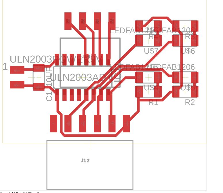
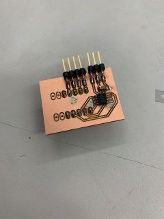
The board has 4 input leads and 4 output leads along with power, and a power and ground line with a current leveling capacitor to the chip.
To determine the resistance levels I would need, I used an online LED resistance calculator. I checked the datasheet for the orange SML-LX1206SYC-TR LED I decided on using and found it dropped 2V under normal circumstances. I set my voltage to 9V because at the moment I hadn’t decided on the power I would have for my motors, and calculated that I needed a resistance of 500 ohms. Our lab had plenty of 499-ohm resistors, so I used those for my board.


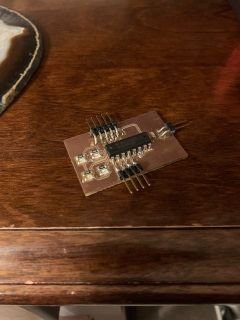
I milled out this board and soldered everything but the uln2003A chip because I was still waiting on it to ship.

On Friday, all my electronics arrived, so I put my final parts together and started testing. Unfortunately, the ULN2003a chip I ordered was through-hole, so I first replaced the footprint in Eagle CADfor the stepper schematic for the through-hole version and soldered everything together.
Software
To start, I tested some code with a standard Arduino and elagoo stepper motor driver board. I downloaded some example code, made a few small changes, and uploaded it to the Arduino UNO. It worked, and the stepper was spinning.
With functional code, I then tested my own board. I used the same Arduino to drive it since my final project will use an ATmega328p chip, which is the same one on the UNO. I connected all the pins and ran an example sketch, but nothing happened. After some probing with a multimeter, I realized that I accidentally hadn’t soldered one of the header pins. I had used a footprint for 6 headers even though I only needed 5, and I had shifted my headers over by one position. I desoldered and resoldered the headers, and the board was working.
Group Work
Our group assignment this week was to observe the power consumption of an output device. I chose a 9V brushed DC motor for this assignment. Our full documentation can be found on our group site.
I used a WANPTEK power supply to view the power, voltage, and current being used.

I then changed the voltage and observed the power used. I used voltage levels of 5V, 7V, 9V, and overpowering it at 12V. I then turned the data into a graph and found an exponential relationship between voltage and power. This makes sense because power is defined as voltage times current, and current increases with voltage.

All my files for this week can be found in this zip file