10. Input Devices
This week’s assignment was to add a sensor to a microcontroller board that you designed and read from it. I will be using the sensor I will use for my final project- a distance sensor.
I started by choosing my sensor. I will use the VL53L1X distance sensor since it had a reasonably large range (~2-4 meters) with high accuracy, which will be useful for my final project.
My final project is to create an autonomous car that can map out a room. The sensor will be used to help guide the car around the room and to detect points in the room.
Datasheet
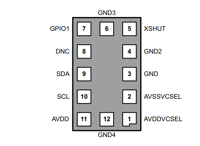
I started the week by taking a look at the datasheet for this sensor. I noticed a few different boards online, some that had only connections between the sensor and header pins and some that included other components, so I wanted to determine if I could control the sensor with just header pins.
In the datasheet, I found the requirements for the sensor and found that it would be possible to just use header pins.
Electronics
Design
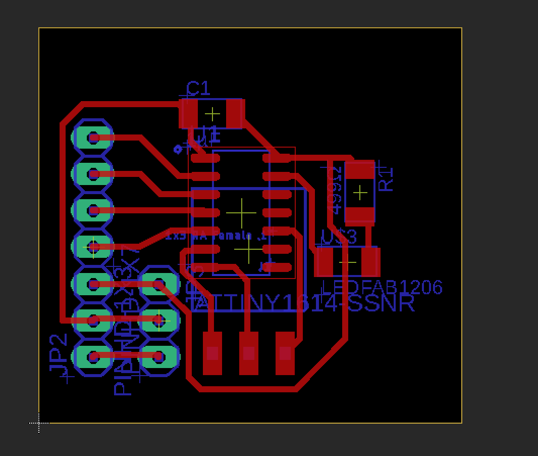
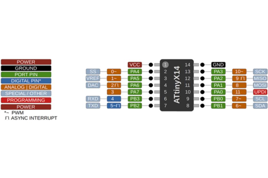
After finding this, I started my work in Eagle CAD to make the board. Originally I created a board with just header pins and the sensor footprint as well as a separate board that I could use to test the sensor, but after learning that the sensor was 2 mm wide and had 10 pads underneath it, I decided to purchase a sensor breakout board. I decided to use the ATTiny1614 chip to test the sensor. To display input data for testing purposes, I added an led to light up at certain ranges.
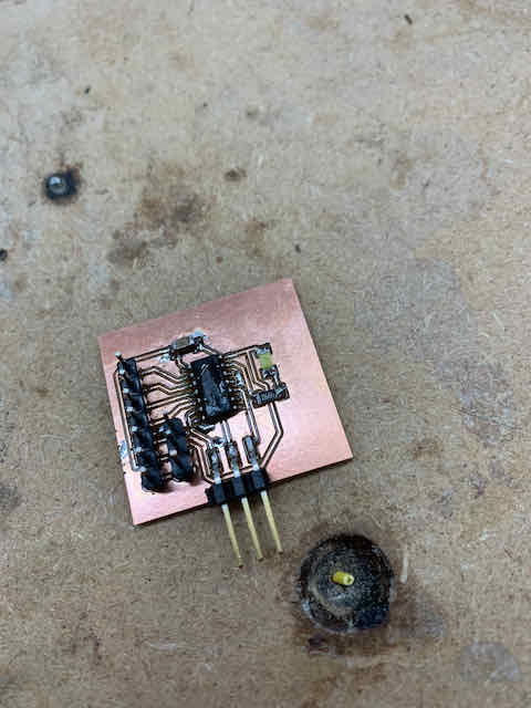
Production
Next, I milled out the board I designed. It milled out nicely, and I soldered it. However, there were a few problems with my board. First, I accidentally forgot to connect power and ground to my header pins (the board design above was after noticing this error). Also, after reading through the datasheet for the ATtiny1614 and my sensor, I realized I had to connect specific pins to my SDA and SCL for the I2C protocol, so I had to redesign my board and schematic.
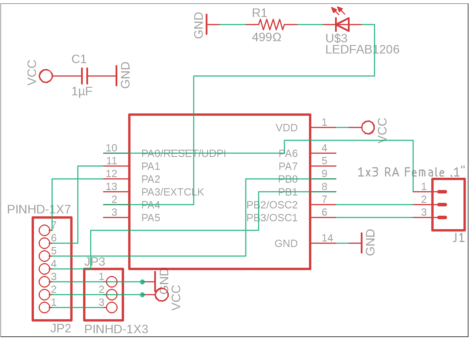
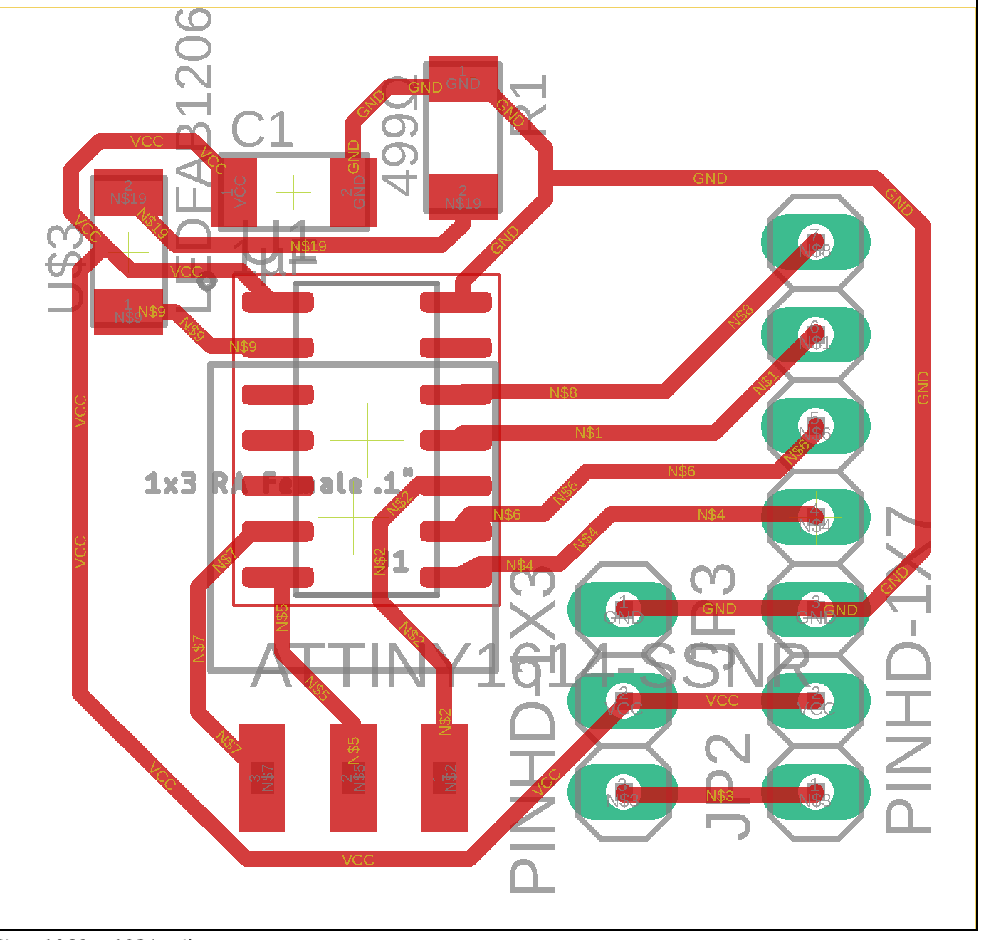
I also consolidated the header pins into 6 pins for the sensor breakout board, 3 pins for VCC/VDD/GND for the boards, and 3 pins for tx/rx/updi.
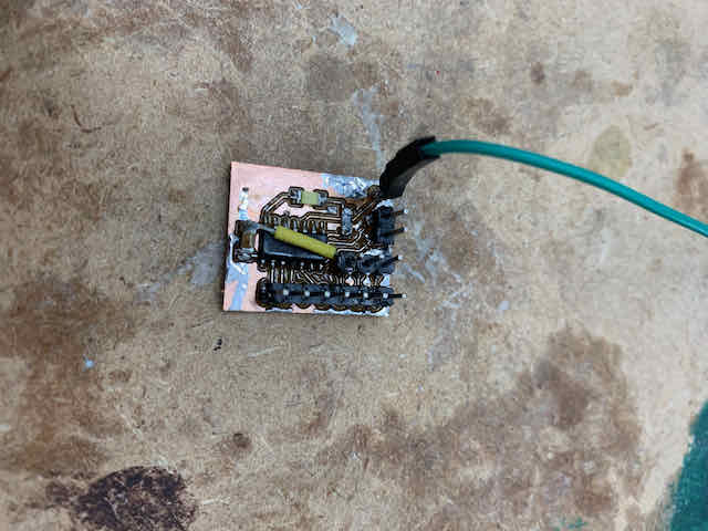
I then milled and soldered my board, and continued with this week.
Software
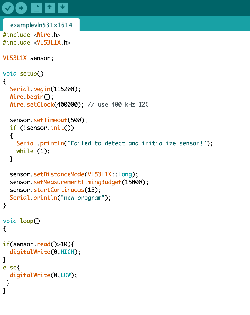
With the boards complete, I started testing the electronics. I looked through the datasheet again to find how I would control the sensor and used it to write code that would read data and light a sensor if the sensor read something in close proximity.
The documentation with the sensor board and library developed by Pololu had very little documentation apart from example codes, so I based mine off of one of the examples.
Serial Communication
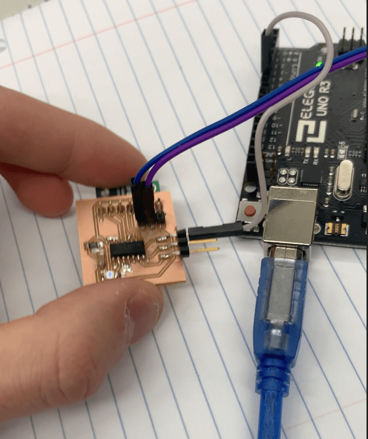
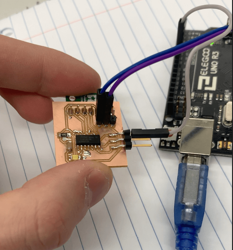
My next step was to establish a serial connection between my 1614 board and my main board. My main board will be an ATMega328p, so I will use an Arduino Uno in its place. I will have Serial communication between the 328 and raspberry pi or computer in my final project, so I decided to try the Software Serial library. To do this, I would set up the 10th and 11th pins on the Arduino Uno as tx/rx pins and connect them to the rx/tx pins on the 1614.
To start, however, I simply connected two Arduino Unos to each other via the tx/rx pins. However, the serial monitor was reading question mark characters. I didn’t have a problem with my baud rate, so I wasn’t sure what was causing the problem. After some time, I realized that I needed a common ground between the Arduinos, and I was able to get the software serial library working between Arduinos. It also worked with the software serial library.
Next, I tried getting software serial to work between my 1614 and Arduino. I used the same code and changed the pins to the tx/rx pins on my 1614 board. However, my program ran into some weird errors. I couldn’t get the code to work reliably. It sometimes returned the ASCII equivalent of a 1 (49), but also returned the numbers 76 and 90. Every time I clicked the reset button on my Uno, the code returned a different number. This is most likely due to some problem with the baud rate, having an unreliable internal clock, or my Serial port setup.
To try to fix this problem, I put in a 1k ohm resistor between the tx and rx pins, and the code worked somewhat more reliably. I then lowered the baud rate to 1200, and I found that almost all of the time I would read 1 on the Uno, and about 10% of the time it would read 64. With the serial communication mostly working, I continued with the software.
I then wrote some simple code to Serial print whatever I read from the sensor, as well as turning on an led for confirmation that the board was working. My code worked, and I put it in the Serial plotter.
However, I wasn’t getting values over 255. I realized that this was because Serial write only sent 8-bit integers, and my numbers were over 8 bits, so it sent two 8 bits per byte. This resulted in the spikes in the serial plotter- it printed the max value, 255, followed by a low value. To resolve this issue, I switched to Serial.println, which would print the ASCII for the number, and used Serial.parseInt() to convert the ASCII into an integer. This code worked, and I was surprised by the accuracy of the VL53L1X distance sensor:
Group Assignment
For our group assignment, we had to test an analog and digital input device with an oscilloscope. We probed a potentiometer for our analog device, and a button for our digital device, and displayed the data on one of our lab’s oscilloscopes.
The full documentation for this week’s group work can be found on our group side.
My files for this week can be found inside this zip file