How to Putt (almost) Anything
Brainstorming project ideas
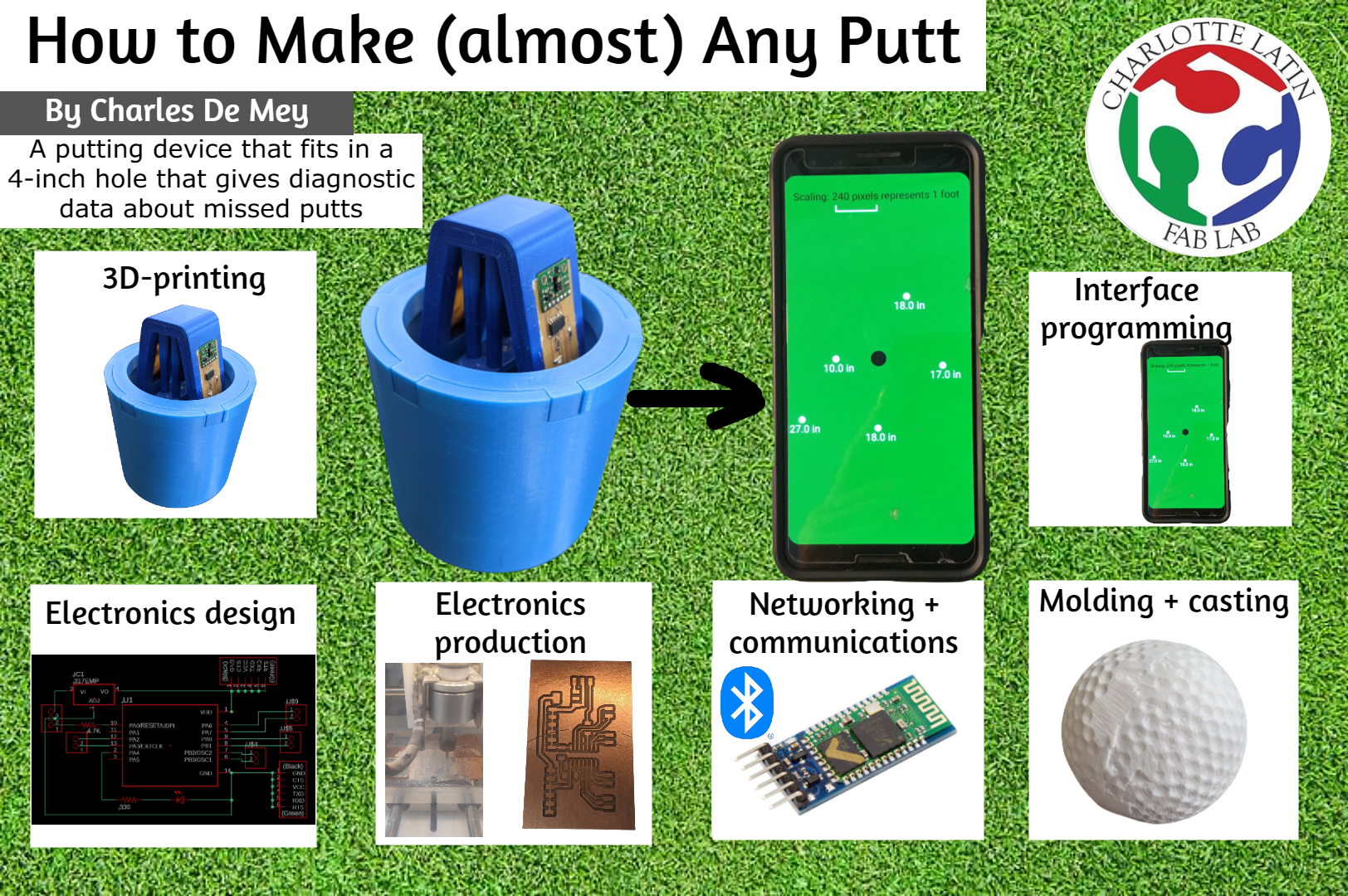
My final project idea is a golf ball returner that will aid golfers in analyzing their accuracy and consistency while putting. I love playing golf, but I hate practicing putting. It is incredibly tedious to putt dozens of balls less than 20 feet away from the hole compared to hitting a driver 250 yards. However, putting is undeniably the most important aspect of the entire game of golf. The average golfer has to putt around 30-40 balls per round, which is vastly more than any other one club or shot. Despite the abundantly clear importance of putting, it is incredibly boring and I rarely putt to improve the stroke and technique. My idea is to create a device that will assist resolve some of this tedium.
Slide + video
How will the device work?
The idea is that after a person putts a ball on a practice putting green, the device will extend a camera above the surface of the hole to start detecting for a ball similar to the phone camera shown below. This is done to ensure that if a putt is successful, it will not knock over the sensor or damage the device in some way.

When the “detect ball” sequence has been initiated, an distance sensor attached to a servo will start rotating. When an object is found within a certain threshold, the device will remember both the position of the servo and the distance of the object. For example, the servo will keep on rotating and then might detect something 131 cm away. The servo will stop spinning and remember the angle value. I will add each of those values to an array and when that value for the array is printed, the result will be “Angle: 72°; Distance: 131 cm”. Then, I will map this on an interface using trigonometry. This will allow the user to identify where they are most commonly missing putts. For example, they might have the correct distance, but always seem to hit next to the hole or it might be that they have a good line, but do not hit the ball hard enough. When the values have been stored and added to the “graph” showing all the missed putts, the sensor will retract and the player will be able to continue putting.
Copyright
The copyright I am applying to my project is the Creative Commons Attribution Non-Commercial 4.0 International. This means that if a person recreates my project, or even references it or uses it as inspiration for their own project, they have to credit me and indicate whether they made any changes themselves. This license also means that my intention is not to commercialize it and nobody can use it for commercial purposes including myself.

This work is licensed under a Creative Commons Attribution-NonCommercial 4.0 International License.
Bill of materials
| Item | Quantity | Cost (each) | In lab or purchased? | Link |
|---|---|---|---|---|
| VL53L1X breakout board | 2 | $11.95 | Purchased | link |
| Servo motor | 1 | $7.60 | In lab | link |
| ATtiny1614 (SMD) | 3 | $0.78 | In lab | link |
| ATtiny412 (SMD) | 1 | $0.51 | In lab | link |
| 4.7K Ω resistor (SMD) | 4 | $0.10 | In lab | link |
| 330 Ω resistor (SMD) | 4 | $0.52 | In lab | link |
| LED (SMD) | 4 | $0.31 | In lab | link |
| Male header pins (SMD) | 44 | $0.1175 | In lab | link (comes in sets of 36) |
| 5V regulator (SMD) | 1 | $0.51 | In lab | link |
| Single-sided PCB sheet | 1 | $1.40 | In lab | link (pack of 25) |
| AA batteries | 4 | $0.92 | In lab | link |
| Battery case holder | 1 | $2.99 | In lab | link |
| Female to female jumper cables | ~25 | $0.21 | In lab | link (pack of 50) |
| Royal Blue Prusament | 1 | $24.99 | In lab | link |
| HC-05 bluetooth module | 1 | $7.99 | Purchased | link |
Interface
My goal for the interface is to have an interactive platform where the player can analyze and discover details about each recorded putt. The idea is that by simply pressing on an an icon that represents one of the balls, the player could learn the exact distance to the hole and the probability of making the putt from that distance. For example, there might be 2 different balls the player might want to analyze. The first was a very bad putt and is still 5 feet away from the hole while the second is only 6 inches away. While it is possible that the player will sink both of these putts, it is far more likely that the player will miss the 15 foot putt rather than the 15 foot putt. Data like this could assist the golfer setting helpful goals.
5 randomly generated x- and y-coordinates
This is an example of the interface with golf balls placed at random angles and random distances. I wrote this on Processing for Android. Visit my interface and applications week to learn more about this code and how to use Processing for Android.
import java.io.*;
import java.util.*;


float x = 0;
float y = 0;

float[] distances = new float[5];

String printable_array = "";

void setup() {
  fullScreen();
  background(47,120,31);
  fill(0);
  circle(width/2, height/2, 90);
  textSize(60);
  stroke(255);
  strokeWeight(6);
  text("Scaling: 240 pixels represents 1 foot", 50, 100, width-50, 250);
  line(300, 180, 300, 210);
  line(300, 210, 540, 210);
  line(540, 210, 540, 180);
}

void draw() {
  fill(255);

  for (int i = 0; i < 5; i++) {
    float x = random(width/2-500, width/2+500);
    float y = random(height/2-500, height/2+500);
    circle(x, y, 33);
    float distance_from_hole = round((sqrt(sq(width/2 - x) + sq(height/2 - y)) / 20) - 2.25);

    if (distance_from_hole <= 0) {
      distance_from_hole = 0;
    }

    distances[i] = distance_from_hole;
    text(str(distances[i]) + " in", x-75, y+75);
  }

  noLoop();

}

Randomly generated angle and distance
The next thing I wanted to do was do the opposite: find the x- and y-coordinates with only an angle and a distance (the hypotenuse of the right triangle). I know that on a cartesian graph the 0 angle is the positive x-axis, but just for visibility I made it the positive y-axis. This meant that everything that was in the range of 0 to 180 degrees was to the right of the hole and everything from 181 to 360 degrees was to the left. Also, since Processing measures angles in radians instead of degrees, I had to use the radians() function on that randomly generated angle.
After I had the angle in radians, I needed to randomly generate a distance. Since my sensors transmit information in millimeters, I will have to convert these distances into inches. This is because in the United States, people say “Oh, that putt was 6 inches left” instead of “That putt was 15 centimeters to the left”. To convert from millimeters to inches I had to divide by 25.4. As mentioned in the scaling section in the first example, 1 inch in real life correlates to 20 pixels on my phone screen. Since Processing will map out points based on pixels, I had to multiply this inch distance by 20 to get the pixel distance.
Then, I used the sin() and cos() functions to find the ratio between that side (opposite of the angle or adjacent to the angle, respectively) to the hypotenuse (the total distance). I can then add these values to the y- and x-coordinates, respectively.
Just like in the first example, I also add some information next to each point. In the first example, I only displayed the distance, but here I will also display the angle (in degrees).
void setup() {
  fullScreen();
  background(47,120,31);
  fill(0);
  circle(width/2, height/2, 85);
  textSize(60);
  stroke(255);
  strokeWeight(6);
  fill(255);
  text("Scaling: 240 pixels represents 1 foot", 50, 100, width-50, 250);
  line(300, 180, 300, 210);
  line(300, 210, 540, 210);
  line(540, 210, 540, 180);
}

void draw() {

  fill(255);

  float random_angle = random(0,360);                               // generates a random angle
  float random_angle_radian = radians(random_angle - 90);           // subtracts 90 degrees and converts to radians
  float random_distance = random(0,650);                            // random millimeter distance
  float random_distance_inches = (random_distance / 25.4) - 2.125;  // converts from millimeters to inches

  if (random_distance_inches < 0) {                                 // if distance is less than 0 ...
    random_distance_inches = 0;                                     // set distance to 0
  }

  float random_distance_pixels = random_distance_inches * 20;       // converts from inches to pixels

  float sin = sin(random_angle_radian);                             // finds ratio between opposite side and hypotenuse
  float cos = cos(random_angle_radian);                             // finds ratio between adjacent side and hypotenuse

  float opposite = sin * random_distance_pixels;                    // calculates actual y-length relative to the hole
  float adjacent = cos * random_distance_pixels;                    // calculates actual x-length relative to the hole

  float x_coordinate = (width/2) + adjacent;                        // adds x-length to hole position
  float y_coordinate = (height/2) + opposite;                       // adds y-length to hole position

  circle(x_coordinate, y_coordinate, 33);                           // makes a circle with radius of 33 pixels at that point

  text(str(round(random_distance_inches)) + " in", x_coordinate - 50, y_coordinate + 75);   // displays the distance from the hole below
  text(str(round(random_angle)) + char(176), x_coordinate - 40, y_coordinate - 40);         // displays the angle above

  noLoop();                                                         // makes the loop run once
}

Angles and distances from master board
Boards
Distance sensor board
During Input Devices week, I designed and made a board for a VL53L1X distance sensor.
Although my final board design is very similar to the one I had during the input devices week, I altered the way the breakout board for the sensor was mounted. Previously, I had used header pins, but to make the best connections between the main board and the breakout board, the breakout board had to be positioned underneath the main board. When I was making a CAD design for the sensor board mounts, I remembered that Dr. Gershenfeld had mounted his boards in a different way as shown below. As you can see, this allowed him to solder the breakout board on the same side as the rest of the components.

I attempted to find libraries for circular, surface mount pads such as that, but I was unable to find anything. Then, I wondered if I could make my own version of that. I ended up finding the Youtube video shown below and was able to make my own symbol and footprint:
Following that tutorial, I was able to make the symbol and footprint for the circle surface mount pads and then use it in my schematic and .brd file. The first step of making your own component like this is making a symbol. This is how the component will be viewed in the schematic file when you connect each of the pins. Then, you have to make a footprint which is what actually will be milled onto the board. On the breakout board for hte sensor, each hole is a circle with a diameter of 0.05 inches and the distance between each center is 0.1 inches. Then, you have to make a device and add the symbol. On the right hand column, there is a section about adding package footprints. If you named the pins in the symbol and the footprint, you can easily press “connect” for each of the pins. Then, you just have to add this library to whatever schematic you are designing like any other component. Download the schematic here, the .brd file here, and the custom library for the pads here.


This is the final result:


This is the code I uploaded to the board to read values. All the distances in the video below are displayed in millimeters. I am using an FTDI chip to read the values to my computer. Download the code for yourself by clicking here
#include <Wire.h>
#include <VL53L1X.h>

VL53L1X sensor;

void setup()
{
  Serial.begin(9600);
  Wire.begin();
  Wire.setClock(400000);

  sensor.setTimeout(500);
  if (!sensor.init())
  {
    Serial.println("Failed to detect and initialize sensor!");
    while (1);
  }

  sensor.setDistanceMode(VL53L1X::Long);
  sensor.setMeasurementTimingBudget(50000);

  sensor.startContinuous(50);

}

void loop()
{
  Serial.println(sensor.read());
  delay(100);
}
Servo board
Master board
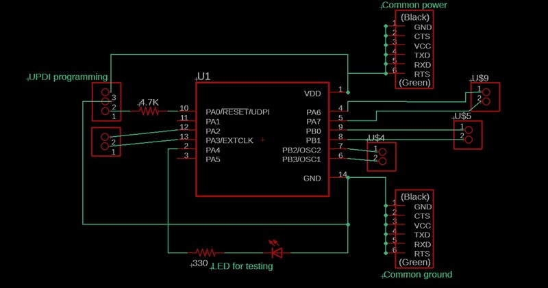
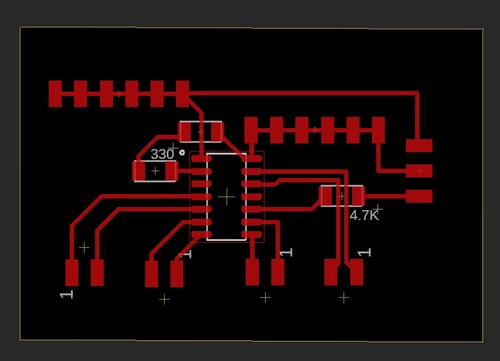
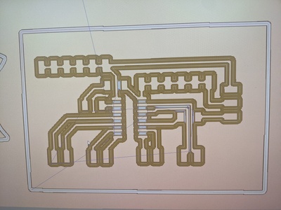
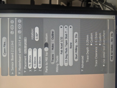
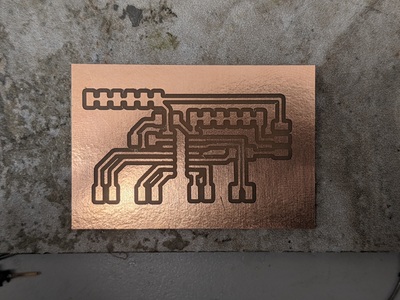
After all the weeks, I had several independent boards, but I needed a master board that could collect information from all those sub-boards. In this central board, other than pins for ground, power, UPDI, and an LED for testing, all the other pins can be used for serial communication. Since each set of software serial pins is only 2 pins, I have space for 4 sets of software serial pins in addition to the 2 built-in serial pins. That being said, it was very easy to design and make board. Download the schematic here and the board file here
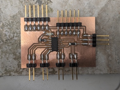
This is a video of me uploading a simple blink program just to make sure that I can upload programs to the board.
I did have to change the board, however. Since I didn’t have any 5V batteries and I didn’t have a lot of leeway in that aspect, I had to redesign the schematic by adding a voltage regulator. The only difference this made on the final board is just that the voltage that powers the microprocessor and all the other components passes through a regulator and that some traces had to be rerouted.

Communication between boards
Software serial
Since I had an FTDI chip connected to the Rx and Tx pins of the master board, I had to use the software serial pins to receive values from one of my input boards. The input board I am using is the time of flight board I designed during Input Devices week.
The code is relatively simple. I just have to start by including the software serial library and then assigning certain pins as the software serial pins. I did this by writing the line “SoftwareSerial input1(9, 10)”. This makes sets pin 9 as Rx and pin 10 as Tx. Then I have to start the hardware serial pins at a baud rate of 9600 and the software serial pins also at 9600 baud rate. In the “void loop()”, I print a counter to show which value is being printed, then spacing for readability, then the value from the distance sensor, ” mm” for units, and then I increase the counter by 1 for the next cycle.
#include <SoftwareSerial.h>

SoftwareSerial input1(9, 10);                       // sets pin 9 as Rx and pin 10 as Tx

int i = 0;

void setup() {
  Serial.begin(9600);                               // starts normal serial monitor at 9600 baud

  input1.begin(9600);                               // starts communication with input1 at 9600 baud
  Serial.println("Input1 has been initialized");
  Serial.println("");                               // adds a line of spacing for readability

}

void loop() {

  if (input1.available() > 0) {
    Serial.print(i);                                // prints counter
    Serial.print("      ");                         // space between counter and distance
    Serial.print(input1.parseInt());                // prints distance value from sensor
    Serial.println(" mm");                          // prints "mm"
    Serial.println("");                             // adds a line of spacing for readability
    i = i + 1;                                      // increases the counter by 1
  }
}
Bluetooth
HC-05 module
The first bluetooth module I tried using was a HC-05 Bluetooth Module. This is important for my final project since the idea of the device is that it detects balls within a certain distance of the hole. If I had to go to the hole to click initiate the “sense” command, the device might accidentally sense myself instead of a ball. This would alter and interfere with the results and measurements. I have posted the data sheet for the bluetooth module below.


I used this tutorial to learn about how the HC-05 module work and I executed a simple example program to turn on or off an LED depending whether I sent an “1” or a “0”.
Connecting to a bluetooth module is very easy. When the module is supplied with power but not connected to any device, the built-in LED will blink non-stop. To connect, go to the settings app and connect the module just as any any other bluetooth device such as a speaker or a computer mouse. This bluetooth module will always appear as “HC-05”. Once it is connected, go to whatever terminal app you are using. On Windows, there is an app called Bluetooth Serial Terminal. Any device that is compatible with this should appear in the “devices” list. If it does not, just click “refresh list”. Once you have found the device, just click “connect”.
Once I connected the bluetooth module to the master board, I uploaded the following program to the board. The idea is that it reads whatever character is coming in through the Serial pins. If that character happens to be a 1, the LED will be turned on and “LED is on” will be printed to the Serial monitor. If the character is a 0, the LED will turn off and “LED is off” will be printed. If any other character is received, nothing changes. As I demonstrate below, I send a 1s and 0s multiple times and the program acts accordingly and when I send the letter “c”, the state of the LED does not change. Click here to download the code for yourself
char junk;
String inputString = "";

int led = 0;

void setup()                    // run once, when the sketch starts
{
  Serial.begin(9600);            // set the baud rate to 9600, same should be of your Serial Monitor
  pinMode(led, OUTPUT);
}

void loop()
{
  if (Serial.available()) {
    while (Serial.available()) {
      char inChar = (char)Serial.read();            // read the input
      inputString += inChar;                        // make a string of the characters coming on serial
    }

    Serial.println(inputString);

    while (Serial.available() > 0) {
      junk = Serial.read() ;                        // clear the serial buffer
    }

    if (inputString == "1") {                       // in case of '1' turn the LED on
      digitalWrite(led, HIGH);
      Serial.println("LED is on");
    }
    else if (inputString == "0") {                  // incase of '0' turn the LED off
      digitalWrite(led, LOW);
      Serial.println("LED is off");
    }
    inputString = "";
  }
}
Once this was done, I wanted to use the Bluetooth module and combine it with the software serial example that I used above. The idea was to use the bluetooth exactly the same way as the FTDI chip, just transmitting whatever data over serial back to my computer. The code I used for this was exactly the same as the code I used in my software serial example above.
As you can see in the video above, the values that are coming through the bluetooth module are not continuous. The counter shows that data is sent in bulks of 10-15 values at a time. This is not ideal for my project since the servo will constantly be changing positions, and the distance might not be viable anymore for the position. I have to find a way to solve this, but I am still not sure how I will approach this issue.
After doing some research and troubleshooting with Dr. Adam Harris, we found this Arduino Forum where somebody was also having the same issue of only receiving data from their HC-05 module every couple of seconds. They were wondering how to resolve this and make the module send data more frequently. At some point during this forum conversation, somebody commented this:

As you can see in the photos of the module earlier in this section, one of the 2 big chips looks like a square while the other is more like a rectangle. This means, that the chips I have are not very helpful for my project. Some people in the forum speculated that the company that manufactures these modules did this on purpose to force customers to purchase the newer Bluetooth Low Energy (BLE) devices instead of these models.
HM-10 Module
The second bluetooth module I experimented with was the HM-10 module. This uses a newer version of Bluetooth called Bluetooth Low Energy (BLE).
I followed this tutorial to get this module working, although the process was almost identical to the HC-05 module.
This is the code I used to just turn on or off an LED on an Arduino. As you can see, I connect the bluetooth module to the software serial pins (2 and 3). When a “1” is sent to the module, the builtin LED (pin 13) lights up. When I send a “0” the LED turns off. The app that I used to connect to the bluetooth terminal allowed me to make buttons that automatically sent a “1” or “0”, although this makes no difference in what is transmitted to the module.
#include <SoftwareSerial.h>
SoftwareSerial mySerial(2, 3);
int led = 13;

void setup() {
  mySerial.begin(9600);
  Serial.begin(9600);
  pinMode(led, OUTPUT);
}

void loop() {
  int i;

  if (mySerial.available() > 0) {
    i = mySerial.read();
    Serial.println("DATA RECEIVED:");

    if (i == '1') {
      digitalWrite(led, HIGH);
      Serial.println("led on");
    }

    if (i == '0') {
      digitalWrite(led, LOW);
      Serial.println("led off");
    }
  }
}
I was able to get this with the previous bluetooth module as well, so this next task was really the “moment of truth”. If it could read serial values continuously just like an FTDI chip, then I know that this board is indeed different and will work better for my project. This meant I used the exact same code where I just print to the hardware serial pins whatever I have coming in from software serial pins 9 and 10 (called input1 in the code). As you can see in the video below, this did work. With the first module, the data was sent in bulks of 15 points, whereas now there was virtually no delay between each reading.
#include <SoftwareSerial.h>

SoftwareSerial input1(9, 10);                       // sets pin 9 as Rx and pin 10 as Tx

int i = 0;

void setup() {
  Serial.begin(9600);                               // starts normal serial monitor at 9600 baud

  input1.begin(9600);                               // starts communication with input1 at 9600 baud
  Serial.println("Input1 has been initialized");
  Serial.println("");                               // adds a line of spacing for readability

}

void loop() {

  if (input1.available() > 0) {
    Serial.print(i);                                // prints counter
    Serial.print("      ");                         // space between counter and distance
    Serial.print(input1.parseInt());                // prints distance value from sensor
    Serial.println(" mm");                          // prints "mm"
    Serial.println("");                             // adds a line of spacing for readability
    i = i + 1;                                      // increases the counter by 1
  }
}
VSync
Vsync is a library for Processing and Arduino that allows for variable synchronization (hence the name VSync). The idea is that whenever the value of a variable changes in the arduino, it automatically updates the value of that variable on the Processing side.
Potentiometer example
The example that is on the Github page for VsSync is just synchronizing 1 variable for the position of a potentiometer and then changing the background color of the Processing screen based off that. I connected the potentiometer directly to the Arduino using the power pin, ground pin, and A0 pin since a potentiometer is an analog device. All credit for these 2 sketches go to Maximilian Ernestus, author of the VSync library.
This is the code that has to be uploaded to the Arduino. The potentiometer has to be connected to Analog pin 0 (A0).
#include <VSync.h>
ValueSender<1> sender;

int analogValue;

void setup() {
  Serial.begin(19200);

  sender.observe(analogValue);
}

void loop() {
  analogValue = analogRead(A0);

  sender.sync();
}
This is the code for the Processing side:
import processing.serial.*;
import vsync.*;

ValueReceiver receiver;

public int analogValue;

void setup()
{
  size(400, 400);

  printArray(Serial.list());
  Serial serial = new Serial(this, Serial.list()[4], 19200);

  receiver = new ValueReceiver(this, serial);

  receiver.observe("analogValue");
}

void draw() {
  background(analogValue/4);
}


Values from servo board
For the next step, I wanted to do the same thing as in the potentiometer example, except with the angle of the servo. The idea was when the servo angle is greater (closer to 180°), the background of the screen gets lighter and when the servo angle is lower (closer to 0°), the screen gets darker. On the servo board itself, I had it print whatever angle it has every time the angle changes. Then, I received that angle on the masterboard and then sent out that variable to the Processing side. To make the wiring simpler, I did not attach the servo, but the angle of the servo was still changing on the servo board.
This is the code I uploaded to the master board.
#include <VSync.h>
ValueSender<1> sender;

#include <SoftwareSerial.h>
SoftwareSerial servo(2, 3);

int servoAngle;
int i = 0;

void setup() {
  Serial.begin(9600);
  servo.begin(9600);

  sender.observe(servoAngle);
}

void loop() {
  if (servo.available() > 0) {
    servoAngle = servo.parseInt();
  }

  sender.sync();
}
This is the code I uploaded to the Processing side:
import processing.serial.*;
import vsync.*;

ValueReceiver receiver;

public int servoAngle;

void setup() {
  size(400, 400);

  printArray(Serial.list());
  Serial serial = new Serial(this, Serial.list()[4], 9600);


  receiver = new ValueReceiver(this, serial);

  fill(255);
  textSize(50);

  receiver.observe("servoAngle");
}

void draw() {
  background(servoAngle / 0.75);
  text(str(servoAngle) + char(176), 50, 50);
}
3D-Printing
Sensor boards mount
The first thing I designed and printed for my final project was a sensor board mount. Since the sensors will have to rotate on a servo, I had to find a way to connect the two. The servo I used already had some horns, so I decided to use that as the connection to the servo itself. The basic idea of the mount is that there are 2 “branches” for each sensor board. As you can see, there is a clear space for each board and I designed this to be press-fit. That means that I need no additional adhesive such as glue or tape to hold the board in place. Each “branch” is set at a 13.5° since the field of vision of each sensor is 27°.
This is what the model looked like in the Prusa Slicer:

These are images that I took at different points in the print:


There are 2 likely causes of this failure. The first is that the printer was under extruding filament. I could have resolved this by either increasing the flow rate of filament or decreasing the speed of the print. The second possible cause is that the device just would not have been strong enough as is. In the Prusa Slicer, I set the perimeter width to 2 layers which is considered relatively weak. In my second attempt at printing, I increased the perimeter width to 6 layers. I also slightly decreased the width and height of the spaces for the sensor boards since I noticed that they were still loose in the broken model.
This is the printed second version of the sensor mount before and after removing all the support structures:


After I had removed the supports, it was time to see if the sensors fit and if they really were “snap-fit”. As you can see in the video below, the boards fit into their places, but easily fall out:
To resolve this issue, first I attempted to hot-glue the boards into their place, but the hot glue did not seem to stick to the filament. After this failed solution, I decided to use superglue and superglue accelerant. I used this to connect the boards to their places and the servo horn to the bottom


Replica hole
This part of the CAD designing was incredibly easy. It was literally just making a circle and extruding the outline. I did this so that I could easily test out on a replica golf hole instead of having to go to a real putting green. Just like a real golf hole, the inner diameter is 4.25 inches. After some research, I noticed that there is not unified depth of a hole, so I just decided to make a hole that was 3 inches deep. The total time it took me to design the model, slice the file, and start the print was about 10 minutes. The longest part of the process was probably waiting for the extruder to heat up to test the filament.
Device case
My final device case has to have space for some very important components, namely the master board, the bluetooth module, the servo board and a battery case. It also has to be a specific shape to fit inside a golf hole.
Just like a real golf hole, the replica hole I made has an inner diameter of 4.25 inches. This allowed me to get an understanding of the clearance I would need between the hole and the device.
When I was designing my final device case, I used the “spiral” technique. Every time I had a good version of the board, I added a component or feature. For example, the very first iteration was just a case for the servo that had space for the wires. Then, I added a space for the servo board, etc. For almost all of these boards and components, I imported them from EAGLE and used a clearance of ~0.15 mm between the board and the actual walls of the inlay.
Iteration #1
Like I mentioned before, the first iteration was just getting a case for the servo. I started off by pretty much making a shelled out cube. I also had a little hole for the wire that contains ground, power, and data. However, I did not take into account that I will also need the same amount of space when I need to put the servo in the box


I then edited the servo model with the little space so I could slide the servo and the wire into the container.


Iteration #2
The second task was adding a space for the bluetooth module and servo board. I decided to make these snap-fit so that I did nto have ot use any sort of adhesive such as glue or tape. I learned this the hard way because on the sensor board mount, if I ever need to replace a part of the board or even the board entirely, something would definitely break since I used superglue and accelerant.


Iteration #3
The next task was adding a space for the master board. I also had to change the previous iteration a bit to allow for this. If you look closely in the images in the “Iteration #2” section, the bottoms of each board section are not level with each other, so I had to change the outlines of each of those sides to rectangles before I started adding a masterboard. Then, I created an inlay the same way as I did before. For this board, the best way to save space and be the most efficient with my design was to actually have the board be placed upside down. Because of this, I decreased from 0.15 mm to about 0.12 mm.


Final iteration
For the final iteration I actually had to put everything together and make a made case and a lid that had all the boards. The images have barely any of the wires connected that need to be connected. There is only the ground and power from the battery pack going to the main board and the 3 pins from the servo being connected to the 3 complementary pins on the servo board.
The basic idea of the final device was to have one half that was the main wall that held the battery at the bottom. Then the second part would be the model that I built up to in the previous iterations. This means it contains the servo, the servo board, bluetooth board, and the master board. I also needed some way to connect the two halves. Since I did not want the top lid to slide whenever the servo moved, I created little slots of which the top lid had the complementary pegs.


There was, however, one major thing I did not take into account: the wires from the sensor boards on the sensor board mount. I must have completely forgotten to put holes for the wires, so I had to drill 2 holes. As you can see in the image below, the plastic looks like it is about to fray and peel off, so I had to use the heat gun to slightly melt and clump all that plastic together.

Molding and casting
During wildcard week, I designed a golf ball mold. The result of that week’s assignment was a pretty lopsided and overall low quality ball. The final mold that I used was Dragon Skin 10NV, but this material was very flexible which made it not ideal for my 2-part mold. For the final attempt at making a golf ball, I used the same wax mold as the one I designed and made in Molding and Casting week. What I tried this time was casting Task 8 by Smooth-On into this. My reasoning was that after I had these 2 halves out, it would be a lot easier to align them and effectively cast the final material. Since this material was not flexible at all, I had a bit of trouble getting it out of the mold, but I could just tap it onto the table with a layer of cardboard in between as shown in the video below (I am not sure why the video froze):

Unlike in my molding and casting assignment, I was not able to simple separate these 2 halves with a razor blade. I had to use my lab’s band saw. I also used this to trim the edges. For the casting into these 2 halves, I used Smooth Cast 300. I decided to use this material because had a lot of it and the end product also is white just like a golf ball.

This is where I encountered a bit of a dilemma. Since the material would not flex at all and the cast stuck to the mold, I had to break the mold with a hammer and chisel. First, I had to separate the 2 halves. I got this very easily, but the cast was still stuck to one of the halves. After that, I just had to break a couple of pieces off to release the golf ball.


There was still a little stub at the top (where I poured the material) so I had to use the band saw again to remove the stub. It seems that the 2 halves were still not completely aligned, so I used our lab’s belt sander to smooth over the drop-off and the place where the stub was. I also included a video of the ball rolling and bouncing. Both of these are not as good as a real golf ball, but that is completely expected when casting a golf ball.
