18. Project development
- Complete your final project and make it ready to present to Dr. Neil Gershenfeld
What tasks have been completed and what tasks remain?
Completed
For my final project (including work from this week), I have completed some crucial aspects of my project. The first of these aspects is communication between the boards and then back to my phone. Software serial is the communication protocol I will use to send and receive information between boards. To do this, I had to design a masterboard that would collect all of the information from all the sub-boards. To transmit all of that information back to my phone / computer, I will use Bluetooth, so I did some experimenting with a bluetooth module called HC-05.
What tasks remain?
There are, however, some important tasks that lay ahead. The most important of these tasks is actually making a device case. The most challenging part of this is the fact that everything has to fit in a small golf hole with a diameter of 4.25 inches and a depth of 4 inches. In this tiny space, I will have to fit a battery pack, a masterboard, a bluetooth module, a servo board, and most challenging of all, the sensor boards mount. That part is the most difficult because if I want the actual sensing part of the board to be about ~0.5 - 1 inch about the ground, the rest of that contraption will be 2 inches deep, leaving me very little space for all the rest.
Another thing is I have to experiment more with the bluetooth module I have (HC-05) or maybe find a new module all together. In the section below when I talk about using this module, I explain how it seems to transmit data in big clumps instead of continuously. When I use an FTDI chip, I receive a dozen values per second at a consistent interval, but with the bluetooth, values come in clumps of 15 or 20 readings every 2 seconds.
I also have to experiment with VSync, the library for synchronizing variables between a board and Processing. This is because if I were to transmit all the data from all the sub-boards through one serial terminal back to Processing, I would have no way of differentiating between a sensor angle or a reading from either of the 2 distance sensors.
What’s working? What’s not?
Working
The software serial is working very well when connected to the FTDI chip, but when I try to transmit the data through bluetooth, the data comes in clumps.
Not working
Although the bluetooth is technically working, I will definitely have to troubleshoot about how to get more consistent data readings. My goal for that is to have continuous readings on the bluetooth, as if I were using the FTDI chip.
What questions need to be resolved?
Like I mentioned earlier, I still need to troubleshoot a lot with the bluetooth and I may need to buy a new type of module if it doesn’t start working correctly. I also suspect that the VSync will take a little while to work
What will happen when?
For these last couple of weeks, I will try to complete tasks in parallel. For example, I will make the device in spirals so that I am entirely sure that a certain part of the contraption works as planned before heading to the next step. With each step, a board mount will be added and after 4 or 5 iterations, I will have a working model. I will make these models by 3D-printing them, so I will have these run overnight or start them at the beginning of the day so I can work on other things while it is printing. While they are printing, I will work on other things such as trouble shooting the bluetooth or figuring out how to use VSync. If everything goes according to plan, I will have 2 days (Monday and Tuesday) to work on my video and slide before I present on Wednesday, June 16th.
What have you learned?
I have learned a lot about communication between the boards with things like the software serial and bluetooth.
On a more general scale, I have learned that almost nothing will every work on the first try and that things will take a lot longer than expected. For example, I anticipated that I could complete the bluetooth in an afternoon, but when I actually sat down and started working, I realized that it would definitely take longer than a mere 3-4 hours.
Final project work
Working on software serial and bluetooth
During the networking and communications week, I used hardware serial to communicate data between boards. For my final project, I’d like to have one master board that transmits the data from all the sub-boards (2 sensors and 2 motors) via bluetooth to my phone. Since the ATTiny1614 only has 2 built-in serial ports (Rx and Tx), I am going to use something called software serial to turn other pins of the processor into artificial serial ports. I can do this because on my master board that collects data from all the other boards, I only need an LED for testing, a pin for the UPDI, ground, and power. Other than that, I have all 10 other pins (including the builtin serial ports) left to use for communications.
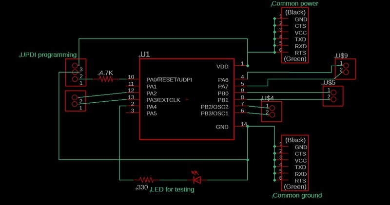
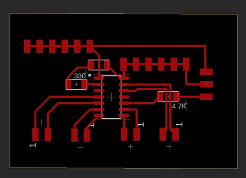
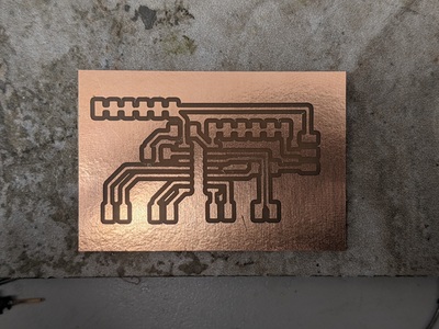
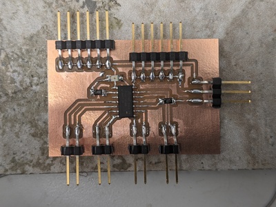
Designing and making a master board
As I mentioned above, all I need on the board is a power pin (which I will turn into a common power), and ground pin (which will also be turned into common ground), UPDI (for uploading programs), and an LED (for testing). Since an ATtiny1614 has 14 pins in total, that leaves me with 10 pins that are available for serial communication. The only thing I had to keep in mind is that I obviously want the 2 pins for each of the devices to be side-by-side. That being said, this board was very simple to design and mill. Download the schematic here and the board file here
Bluetooth
FOr the bluetooth communication, I am going to use a HC-05 Bluetooth Module. I have posted the data sheet below.


I used this tutorial to learn about how the HC-05 module work and I executed a simple example program to turn on or off an LED depending whether I sent an “1” or a “0”.
Connecting to a bluetooth module is very easy. When the module is supplied with power but not connected to any device, the built-in LED will blink non-stop. To connect, go to the settings app and connect the module just as any any other bluetooth device such as a speaker or a computer mouse. This bluetooth module will always appear as “HC-05”. Once it is connected, go to whatever terminal app you are using. On Windows, there is an app called Bluetooth Serial Terminal. Any device that is compatible with this should appear in the “devices” list. If it does not, just click “refresh list”. Once you have found the device, just click “connect”.
Once I connected the bluetooth module to the master board, I uploaded the following program to the board. The idea is that it reads whatever character is coming in through the Serial pins. If that character happens to be a 1, the LED will be turned on and “LED is on” will be printed to the Serial monitor. If the character is a 0, the LED will turn off and “LED is off” will be printed. If any other character is received, nothing changes. As I demonstrate below, I send a 1s and 0s multiple times and the program acts accordingly and when I send the letter “c”, the state of the LED does not change. Click here to download the code for yourself
char junk;
String inputString = "";

int led = 0;

void setup() {                   // run once, when the sketch starts
  Serial.begin(9600);            // set the baud rate to 9600, same should be of your Serial Monitor
  pinMode(led, OUTPUT);
}

void loop() {
  if (Serial.available()) {
    while (Serial.available()) {
      char inChar = (char)Serial.read();            // read the input
      inputString += inChar;                        // make a string of the characters coming on serial
    }

    Serial.println(inputString);

    while (Serial.available() > 0) {
      junk = Serial.read() ;                        // clear the serial buffer
    }

    if (inputString == "1") {                       // in case of '1' turn the LED on
      digitalWrite(led, HIGH);
      Serial.println("LED is on");
    }
    else if (inputString == "0") {                  // incase of '0' turn the LED off
      digitalWrite(led, LOW);
      Serial.println("LED is off");
    }
    inputString = "";
  }
}
Software serial
Since I had the HC-05 bluetooth module connected to the built-in Rx and Tx pins, I had to use the software serial pins to receive values from one of my input boards. The input board I am using is the time of flight board I designed during Input Devices week.
The code is relatively simple. I just have to start by including the software serial library and then assigning certain pins as the software serial pins. I did this by writing the line “SoftwareSerial input1(9, 10)”. This makes sets pin 9 as Rx and pin 10 as Tx. Then I have to start the hardware serial pins at a baud rate of 9600 and the software serial pins also at 9600 baud rate. In the “void loop()”, I print a counter to show which value is being printed, then spacing for readability, then the value from the distance sensor, ” mm” for units, and then I increase the counter by 1 for the next cycle.
#include <SoftwareSerial.h>

SoftwareSerial input1(9, 10);                       // sets pin 9 as Rx and pin 10 as Tx

int i = 0;

void setup() {
  Serial.begin(9600);                               // starts normal serial monitor at 9600 baud

  input1.begin(9600);                               // starts communication with input1 at 9600 baud
  Serial.println("Input1 has been initialized");
  Serial.println("");                               // adds a line of spacing for readability

}

void loop() {

  if (input1.available() > 0) {
    Serial.print(i);                                // prints counter
    Serial.print("      ");                         // space between counter and distance
    Serial.print(input1.parseInt());                // prints distance value from sensor
    Serial.println(" mm");                          // prints "mm"
    Serial.println("");                             // adds a line of spacing for readability
    i = i + 1;                                      // increases the counter by 1
  }
}
As you can see in the video above, the values that are coming through the bluetooth module are not continuous. The counter shows that data is sent in bulks of 10-15 values at a time. This is not ideal for my project since the servo will constantly be changing positions, and the distance might not be viable anymore for the position. I have to find a way to solve this, but I am still not sure how I will approach this issue.