This week, we had two tasks to fullfill. First of all we had to use a vinyl cutter to create some kind of sticker.
Second task was to parametric design a construction kit in an use a laser cutter to create it. Important was the calculation of the kerf and the customizybility.
For the first task I used our Silhouette cameo and the corresponding silhouette studio software, to vectorize an jpg image and the cut it out of sticker paper.
I opend Silhouette Studio and imported the FabLab Logo as jpg file:

![]()
Then I used the trace function on the right side to trace the outlines of the logo, as I only want to cut these out of the sticker paper:

Here you can see the difference between the logo and the traced lines, these red lines will then be cut on the vinyl cutter:

Once you are happy with your design and finished with tracing you can go to the "Send Tab". I selected Sticker Paper as Material, set the action to cut and selected the matching knife:

After all settings are set you click send and the cutter will start.
As you will notice the file I used in the images above and the final result are different. This is due to me, who forgott to take screenshots while creating the final sticker. While creating the tutorial above at home the original file was not available anymore, that's why I switched to the FabLab Logo^^
For my test I cuttet a design a friend of mine made for his "The Dark Eye" Pen and Paper role play game character as a little gift.
Due to copyright reasons I can only show the final sticker, as I am not allowed to share his design online.

One part of the second task was to use parametric design to create a construction kit, which the will be cuttet out on the laser cutter in part two.
The main part of parametric design is the use of global parameters, that you set up beforehand, which you can change and edit later on. You use those parameters to define thinks like the width of the material or the dimensions of the finisched project.
In my design I used parameters like materialwidth, the amount of interlocking theeth, the overall dimensions of my parts etc...
As a construction kit I decided to create a little marble track, which can be individually set together. I had a lot of ideas in mind, due to the time limit I had to reduce my ideas to the basics...
For designing I used Fusion 360, as this is my main programm and I use it quite often. I googled how to set up parameters in Fusion 360, as I have never used those before.
I quickly found out, that you set them as a type of variable and give them a vallue, and after that you can use them in your sketch.
Then I started designing a base track with a lot of parameters set. Additionally I designed the corresponding walls, so that the marble can leave the track:

You can see, every dimensioning that starts with "fx:" uses one or more parameter to calculate the value.
The designing took quite some time, as I maybe have set to many parameters, which made everything much more complex. The Track alone uses 12 individual parameters.
After the base track I designed a curve and the corresponding walls for it. As the walls need to be bend I used a example file from Aaron Porterfield on his Instructables page and imported it into my sketch.
I then sized the cutout pattern to the size I needed and combined it with my design.

As last track part I designed a devider / merger piece, where the track can be devided into two tracks or combined back to one track:

Next I needed something to hold those tracks in the air and let them tilt to a certan dregee, so that the marble will roll naturaly. Each of those tracks got little anchors on the side, which let them connect to the bars, which support them.
I designed the first one two be exactly the sice of one base track, so that I can connect them in a horrizontal or vertical way. I will show you what I mean later.
Then I designed a connecting bar, which is as wide as the base track and will stabelize the support bars.
At last I dublicated the first bar and changed the dimensions, so that I have a lot of different sized bars to choose from. I also created little platforms to hold the bars on the ground.

In total I used 32 different parameters. In retrospect I maybe used to much, cause they sometimes lead to Fusion 360 crashing while changing one of the main parameters like the material thickness. But in the end I can fully customize my tracks, the count of the interlocking teeth and much more.

After I was satisfied with my design I went on and lasercutted the first test parts. I quickly realized, that I forgott to calculate tollerance values in order to get a thight fit between my part. I measured that our Lasercutter roughly burns 0.35mm of material, which I had to add to my joints.
After I updated my design with the new tollerance values I cutted one piece of every track, just to be sure, that everything fits.
I imported my files into RDWorks V8, which is the software of our Lasercutter.


I then set the setting for my cut job and send the data via USB-cable to our lasercutter:


After that I set the Lasercutter above my cuting material and used the auto focus, to set the perfect cutting hight:

Then I set the origin and used the frame function, which visualizes the size of the cut job by moving arround the job and showing you the boundries.

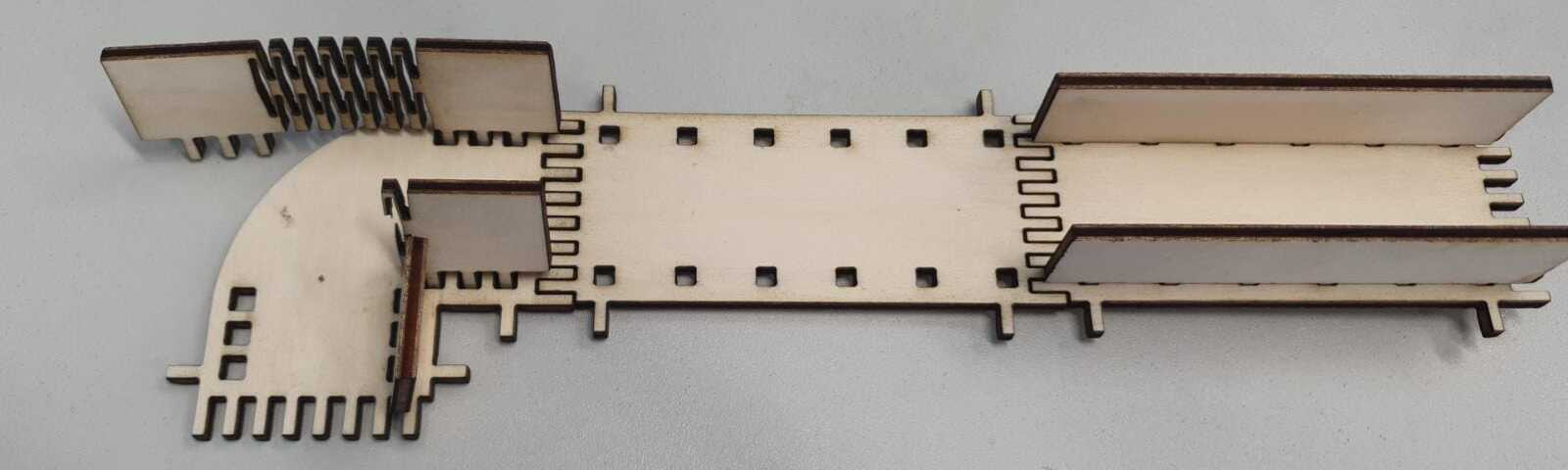
The cut came out nice, everything fitted and the parts came together quite nice:

I cuttet more tracks, curves and devider so I could create my individual marble track:


Then I went on and cuttet the support bars and connecting bars. Sadly I might cutted to much on this day, because the filter system of our lasercutter could not keep up and I quickly noticed a lot of smoke and wood particles on may parts.
I made a video of the lasercutter cutting and you can see the smoke building up to be like fog:


As group assignment we had to characterize the lasercutter we are using. Due to the pandemic situation we could not work together in a group, but we disscussed and decided our steps online.
In our FabLab we have a GS100160 PR from GS Laser Systems with following specs:
| Quick Specs | |||
|---|---|---|---|
| Laserclass | 1 | Lasertype | CO2-Laser |
| Laserpower | 150W | Wavelenght | 10600 nM |
| Max. Engraving Speed | 1000 mm/s | Max Cutting Speed | 100 mm/s |
