
This week we had to design a mold, mill it with at least a rough and a three-axis finish cut and then use it to cast parts.
I had a lot of Ideas for this week and wanted to try out so many different things, but most of them didn't work due to different reasons, so let me tell you why and what worked in the end:
For a while now we have a Babyplast Micro injection molding machine at our FabLab, which I always wanted to try out.
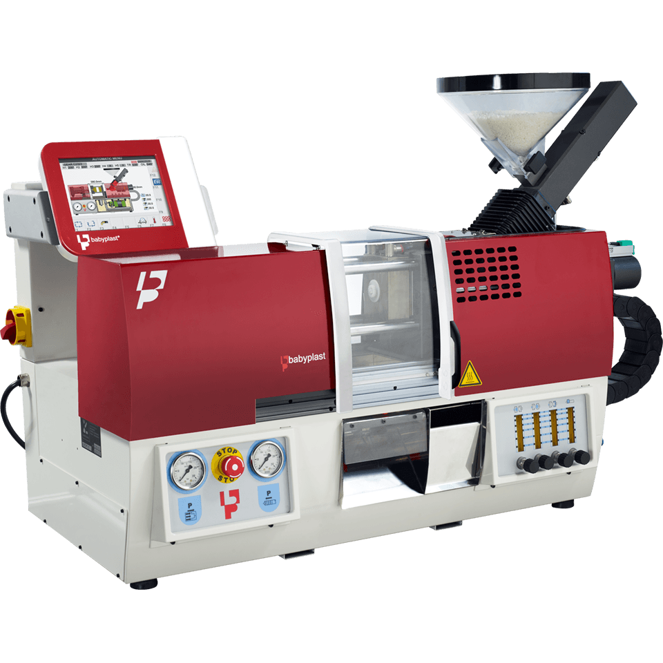
So I thought this week would be the best reason to get used to the machine and make my first test injections. Little did I know that injection molding is a highly complex field and just trying it out would not work.
Also, and that's the part where I realised that I should focus on other ideas, was the fact, that the machine is not connectet to our power grid, nobody has ever used it and there was little to no documentation available at this moment.
So I set this Idea beside, but I will definetly try it out sometime in the future!!
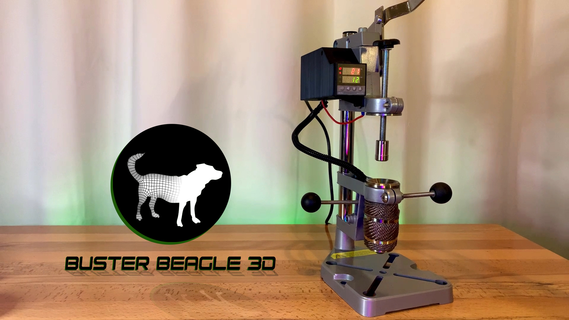
So after realising that my first Idea wasn't the way to go for this week, I remembered, that I had found a DIY injection molding machine on youtube, which I'd like to build and try out.
The small Youtuber Buster Beagle 3D posted a Video with a detailed list of parts and a step by step tutorial on how to build your own injection molding machine.
I was very excieted and started to order the parts I need, only to realise, that those parts would need to long to arrive here in germany, so that I also could not use it in this weeks assignment...
Never the less I will try to use it in my wildcard week, hopefully it will work out ^^.
After both of my Ideas did'nt work out as I had planed, I came up with an Idea I had long time ago, but didn't find it that interesting in the beginning. At the End it kinda worked out, so I'm glad I tried it.
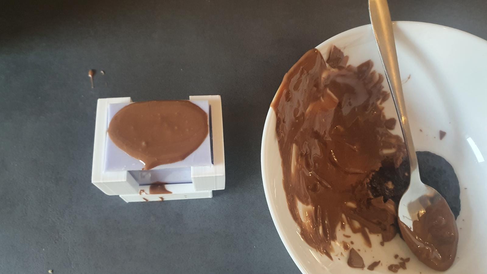
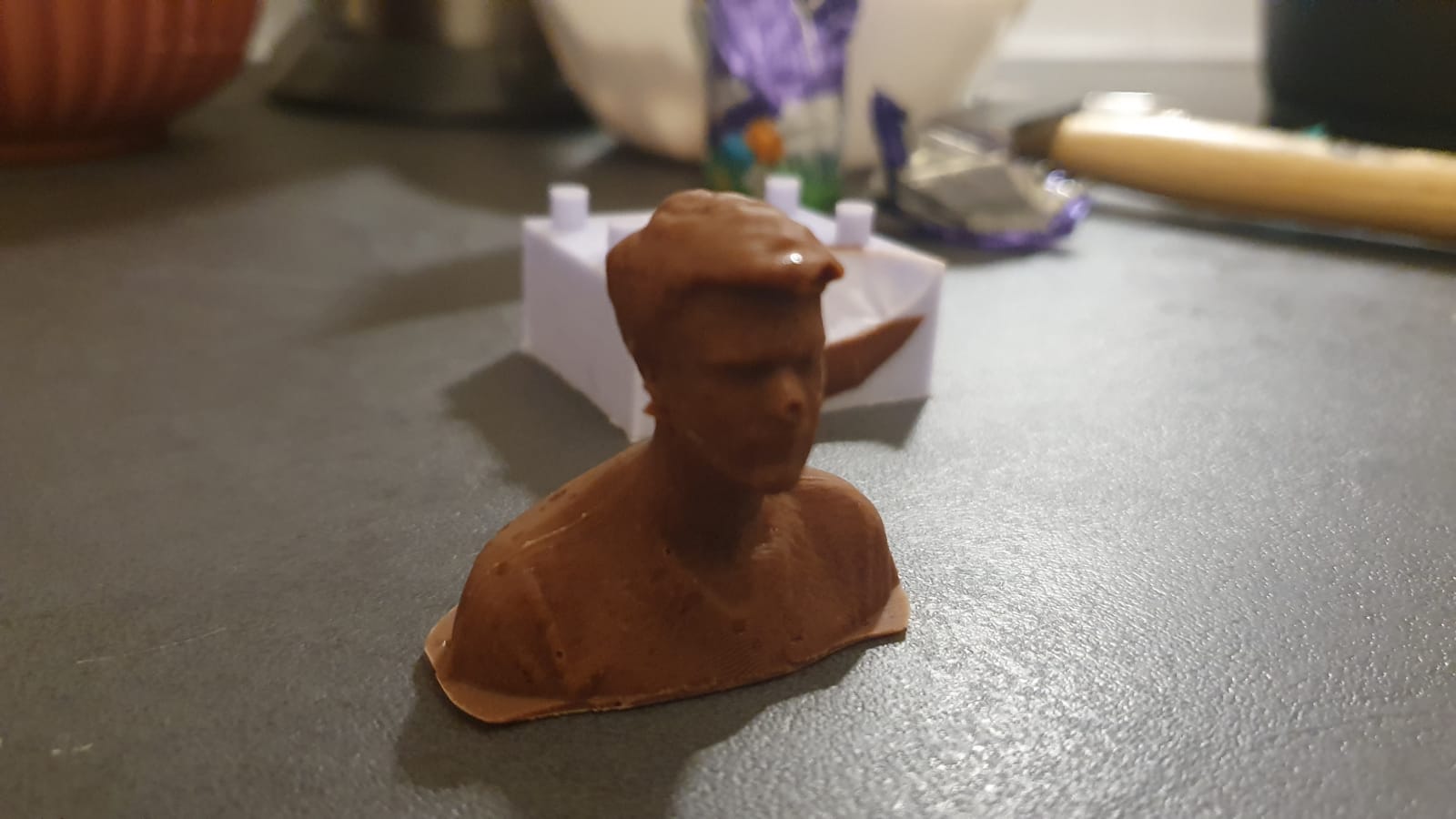
From the work at my bachelor thesis I had some food safe silicone leftover, which I wanted to use to create a Mold of my head, so I can make little chocolate me^^
The Plan was to 3D-Scan myself, import the 3D-model into Fusion, create a positive form which I could mill out on our CNC-Machine, the cast a negative form out of the food safe silicone and the mold chocolate and fill the form:
First Step for me was to get a 3D Model of myself. I our FabLab we have create many 3D-Scan of visitors and other people but I never create one of myself.
So I borrowed our iSense Scanner from our Lab and quickly explained my girlfriend, how to use it. She had to try it a few time but in the end I got this model of myselfe:
After exporting the 3D-Model of myself I imported it into Fusion 360, as it is the CAD / CAM software I'm used to work with.
As I described before, I wanted to make a positiv mold for my negative mold... sounds complicated, but you will see in a moment what I mean^^
At first I had to cut the model of myself in half, so that I can create two mold halfs, which will be later held toghether in some form.
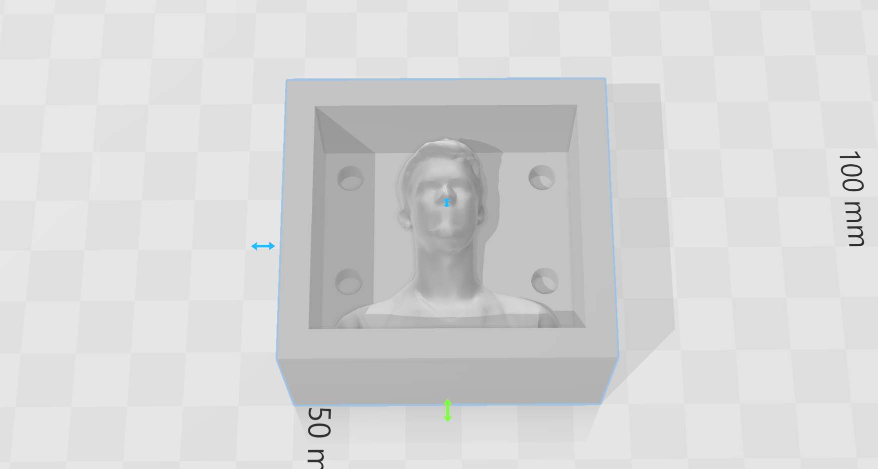
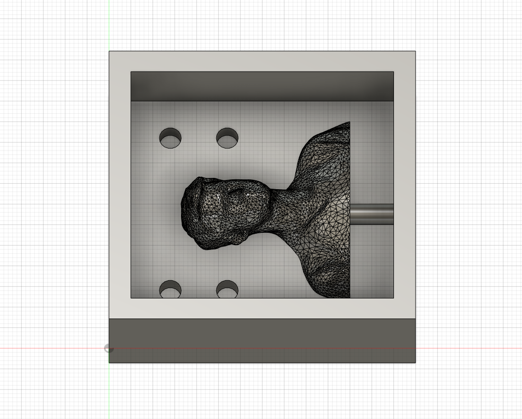
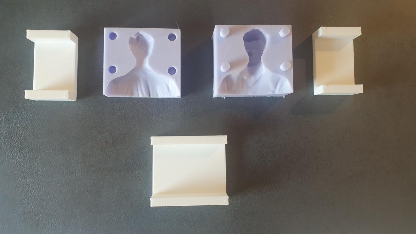
I then created two seperate container, one for each half, which will be a bit different from each other:
The smaller one was designed for 18mm thick plywood and contains the smaller half of the cutted model aswell as positive pins for alignment:
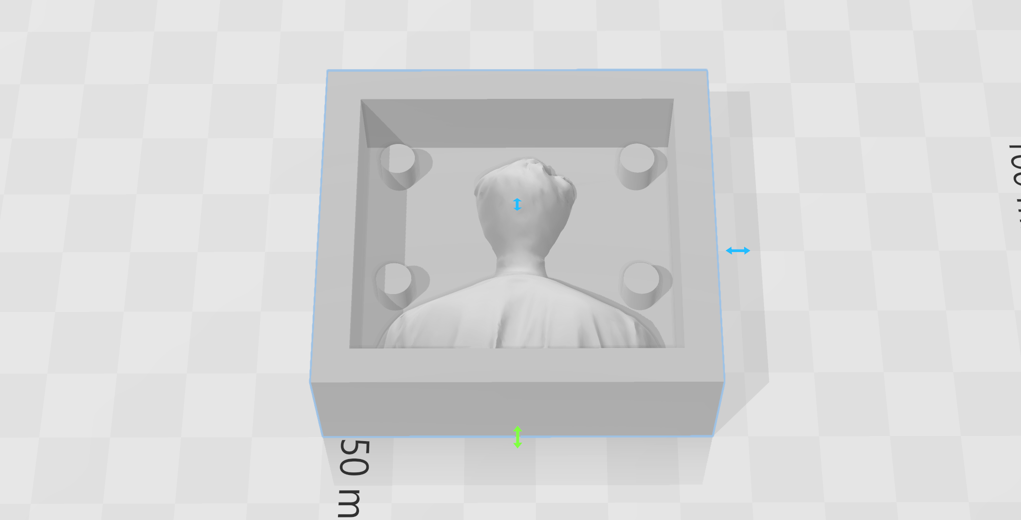
The larger one was deigned for 30mm thick plywood and contains the larger half of the cutted model aswell as the negative cutouts for the alignment pins:
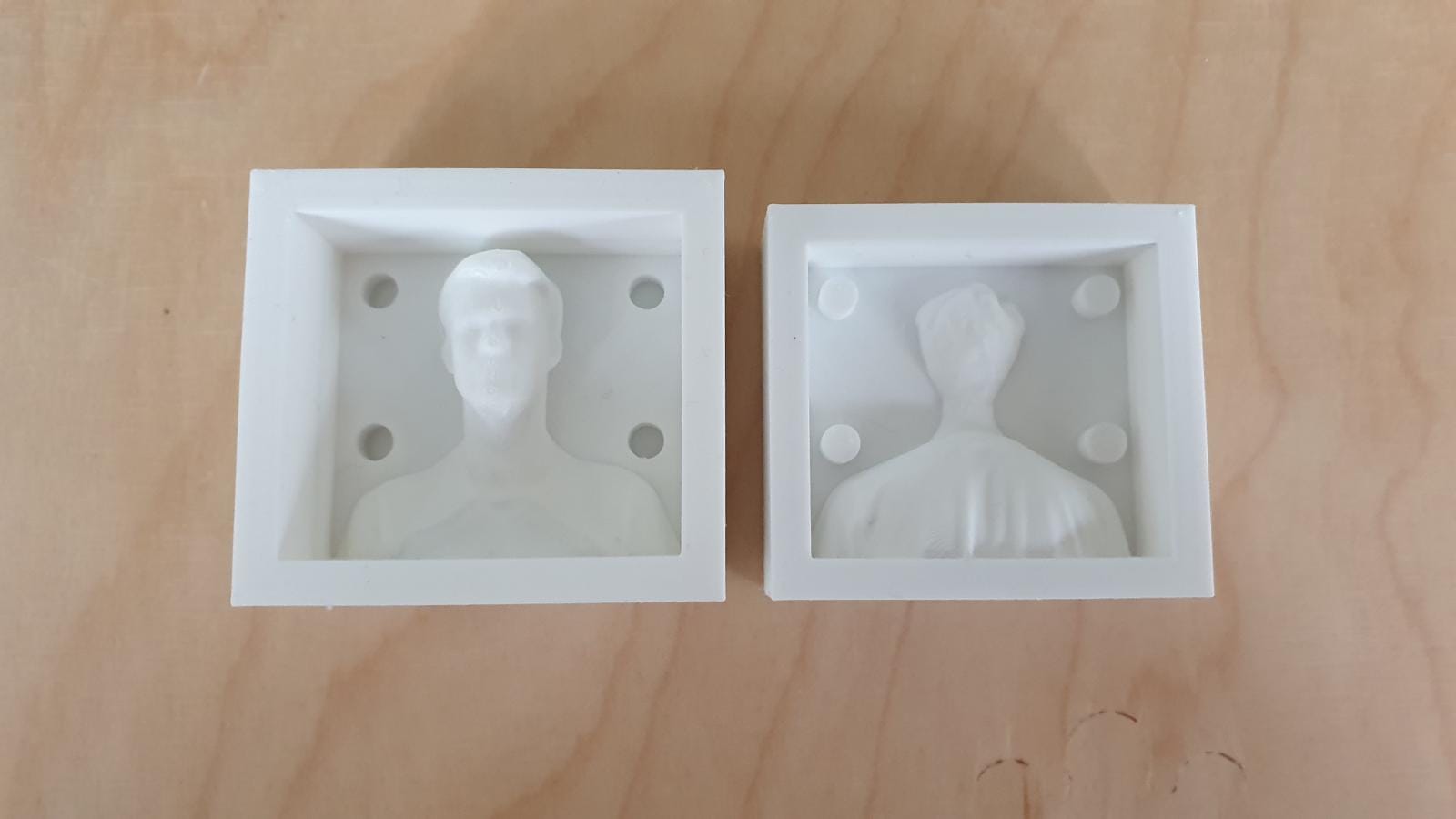
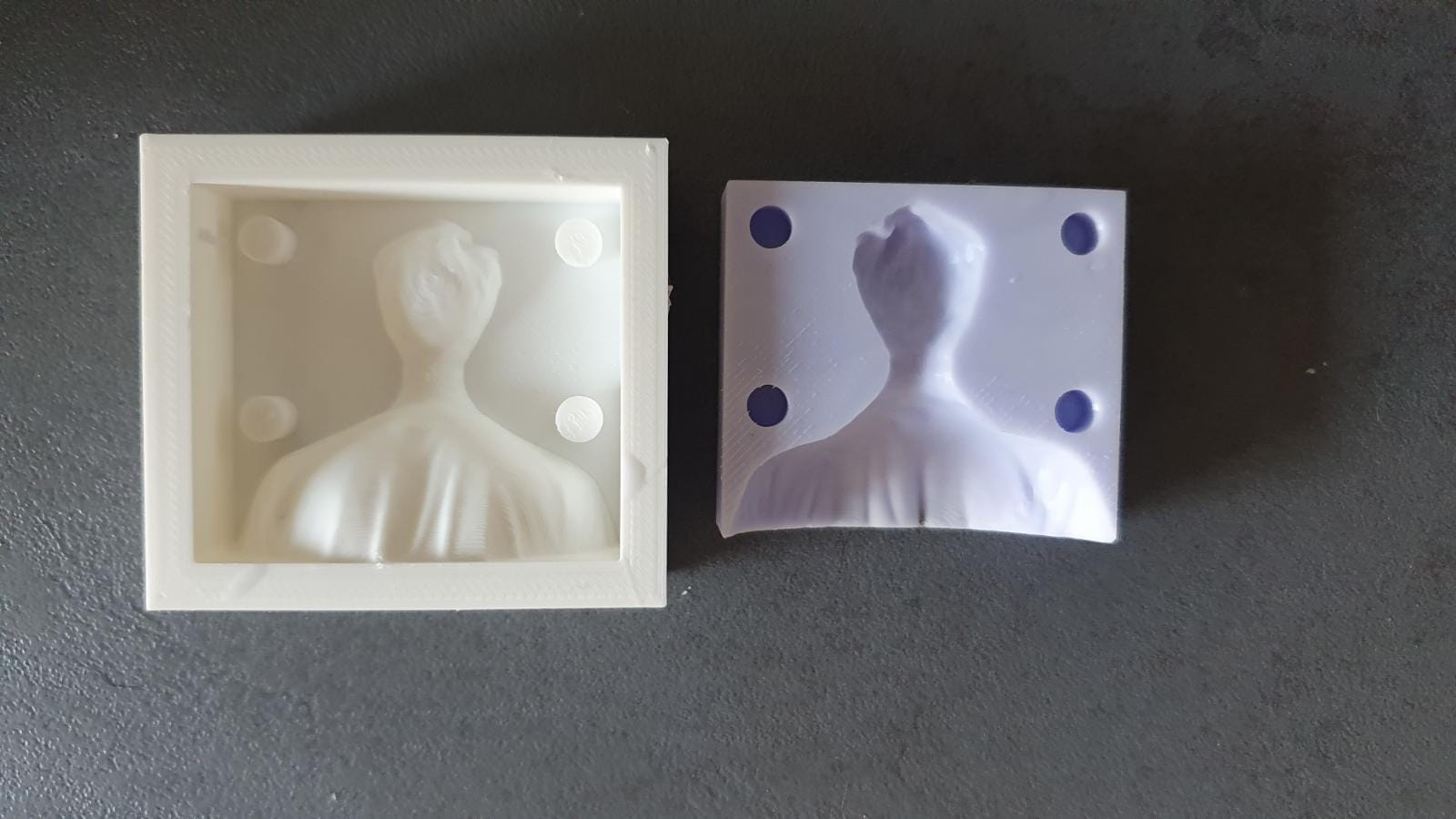
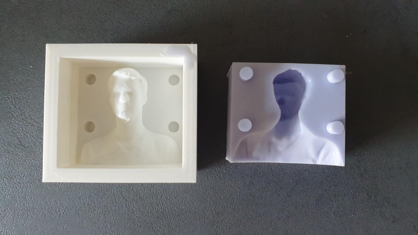
As I didn't know, if my plan and my design will work as intended I exported the mold-halfs and printed them on my 3D printer. I know that I could not use them to fullfill the tasks of this assignment but I wanted to have them in case the milling didn't work or something goes wrong.
In retrospect I'm glad I printed them, but you will see later why^^
Anyway here are the printed halfs as backup plan:
While my backup plan was printing I started working on the gcode generation for my cnc machine.
I had never used Fusion 360 for this type of application before, so I quickly searched for a tutorial and found this one on Youtube, which helped me a lot getting started and basic steps to work:
How to Get Started With CAM Within Fusion 360
As learned in the tutorial I started with the basic setup:
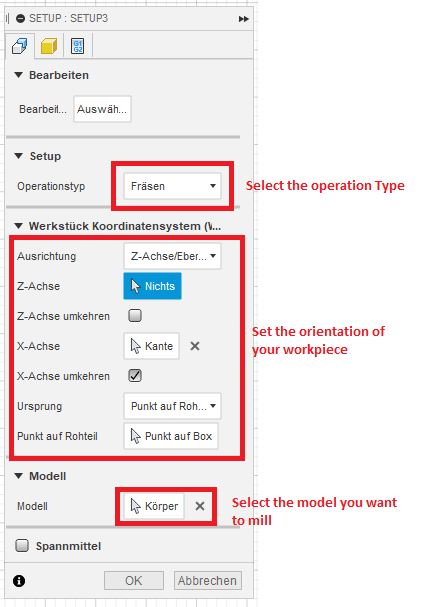
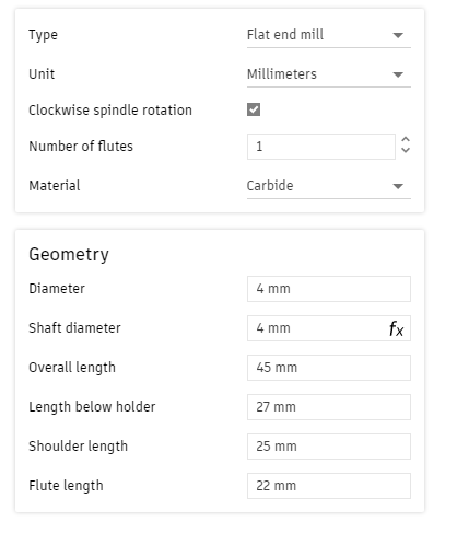
I set up the 4mm single flute flat end cutter with the following settings:
I then added a first 3D pocket clearing as a rough cut fpor removing most of the material in the first place.
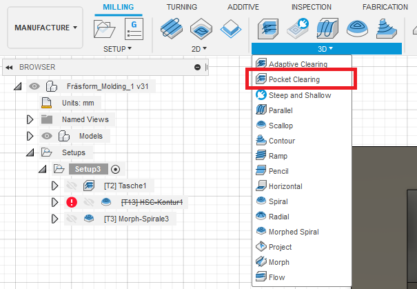
![]()
As I was not experienced enough I stayed with the basic settings.
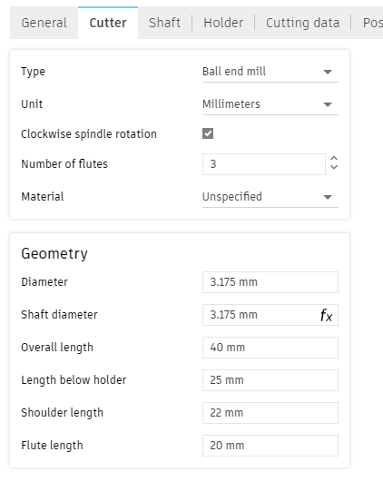
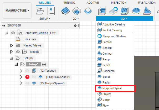
After that I did the same thing for the morphed spiral cut. I first set up the 1/8" ballpoint cutter I had with the machine:
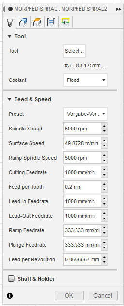
I then added a morphed spiral cut with the basic settings in place:
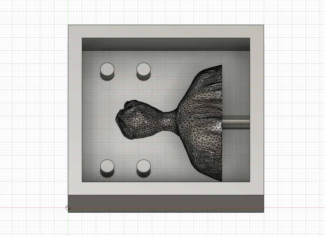
After I was finished I used the inbuild preview to check my settings and if everything was set correct.
Thats when I noticed that my 4mm bit was to thick to reach some areas, so I got back to the original model and made the mold container a bit larger, so that all bits would easily fit.
The new models are shown here:
As you can see I changed the position of the alignment pins and added a way to cast my chocolate into the mold after the two halfs where put together.
After everything was set up for the second model I used the post process tool to create the gcode for my cnc machine.
As the small one in our lab is a generic 3 axis cnc machine, I selected GRBL as processing type and exported the gcode as .nc file:
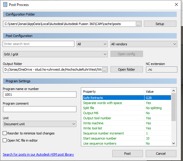
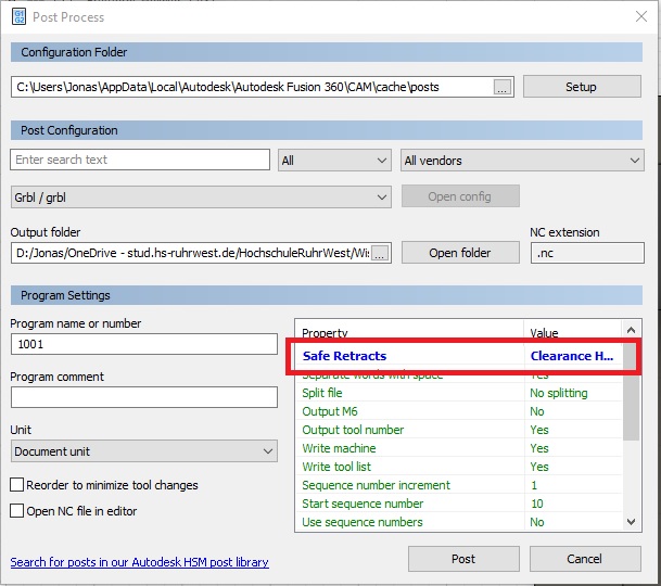
As I will describe late I found out that the basic settings were wrong and that I had to change the "Safe Retracts":
As I was now ready to mill my first part I starte a program called "Universal Gcode Plattform", which can establish a serial connection via USB to different devices like 3D printer and CNC-Machines and send the gcode.
The different buttons are very self explaining, so I won't cover them here. If you are interessted in learning more you can find more inforamtions here:
Universal Gcode Sender
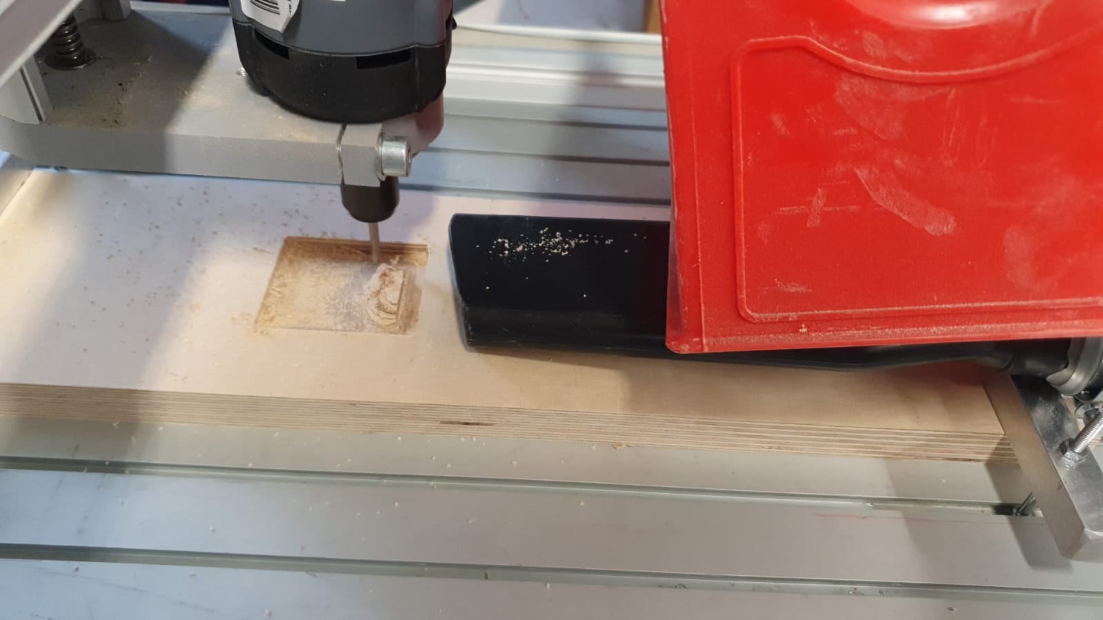
I connected our machine and loaded the 4mm single flute flat end cutter. I then fixed a piece of 18mm plywood to the machine and set my zero position where I needed it.
I turned on the spindel with 10.000 RPM, which was the lowest setting, and started the run.
I quickly realised, that the machine was not moving as I expected it, but I was to slow and the machine began to cut into the aluminium clamp...
I stopped the machine, set a new zero position and started again, only to see the same thing happen, the mill cutting into the clamp, not into the wood...
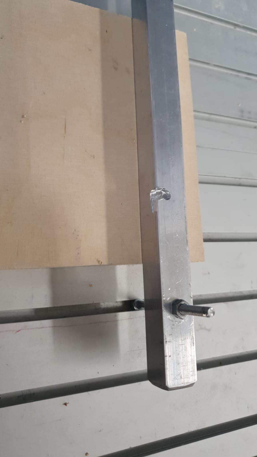
After a second of thinking I opend the .nc file with Notepad++ and discovered a G28 command, which tells teh machine to home to it's original positions. I was a bit frustrated, removed the command and started again.
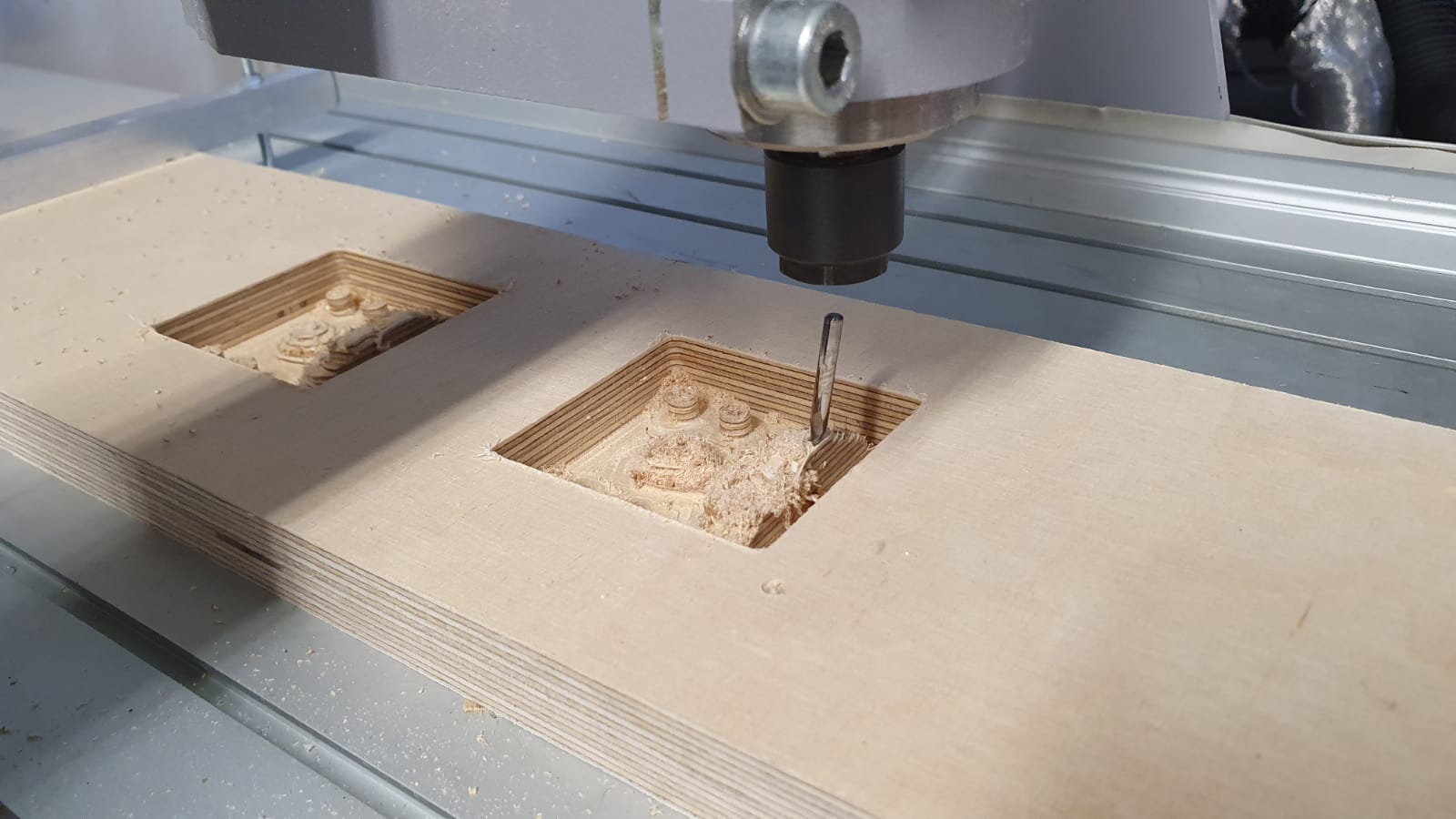
This time the cut workes as expected and the CNC-Machine began to remove material where it should do.
I was very happy to see the machine working like it should, but my good mood vanished, as the machine finished it's cut 30 minutes after I started I and moved straight into the clamp again -.-
I was quick enough to hit the emercency stop, but through this the machine lost track of it's coordiantes and I had to start over again...
After inspecting the .nc file again I found out that I was dumb enough to forget the second G28 command at the end of the process...
So I look up in Fusions post processing and found the option to turn off G28 commands, as written before.
I generated the files again, set a new zero position and started a second cut.
As expected the 30 minutes went as it should and the machine finished, so that I could change the bit and start the second run.
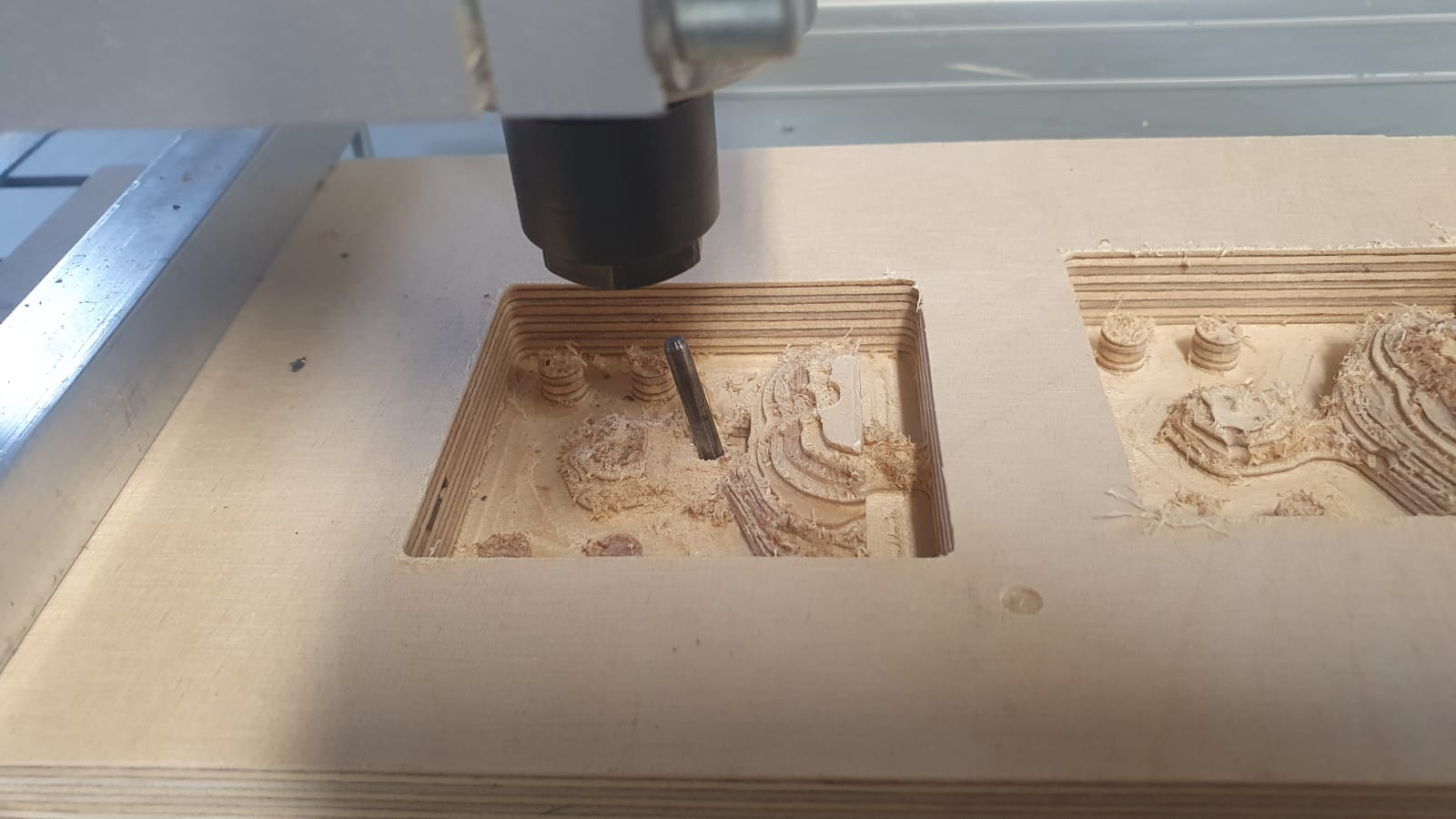
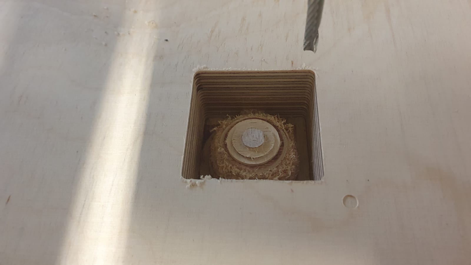
Halfway trough the second run the ballpoint bit came loose and I had to stop the machine againe, loosing all my progress:
I thoughed that maybe the collet wasn't tight enough, so I again set the zero point, changed the bit to 4mm falt end and started a third time.
As before It worked, I changed the bit to the ballend, started the run and...
It crashed again!!!
Now I had three failed attempts and was very unhappy:
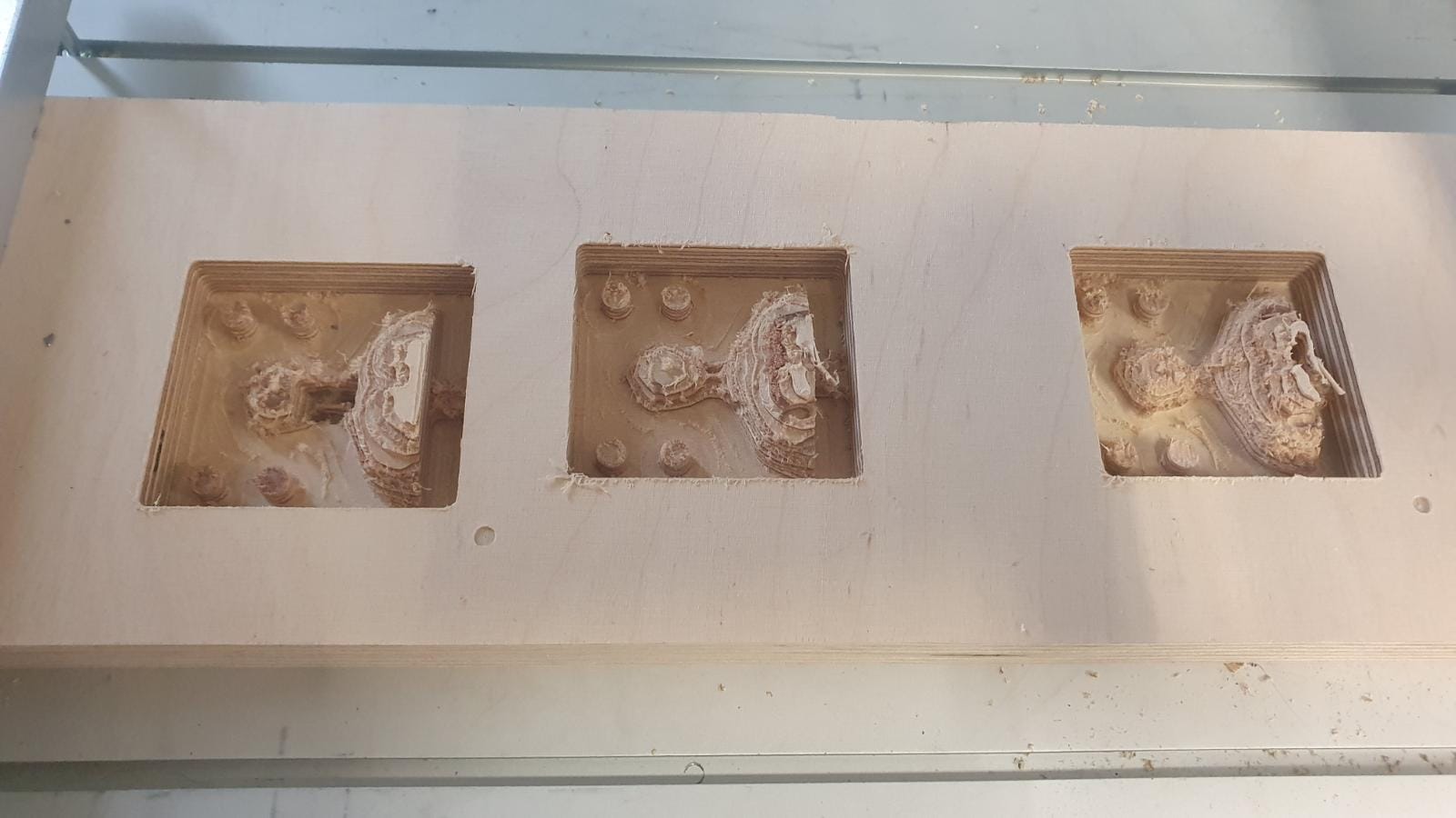
I was so frustrated that I gave up with this model and quickly designed a new, very simple one, so that I at least got something to show...
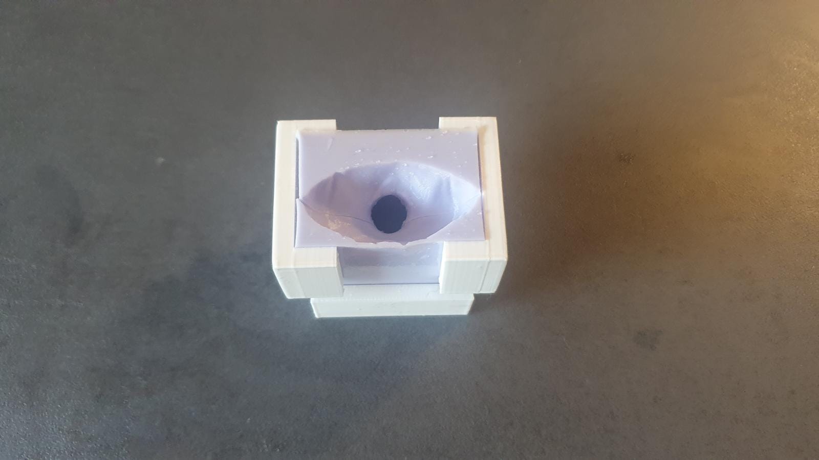
I made a half sphere, which should be easy enough to cut and good enough to use a 3 axis finish cut:
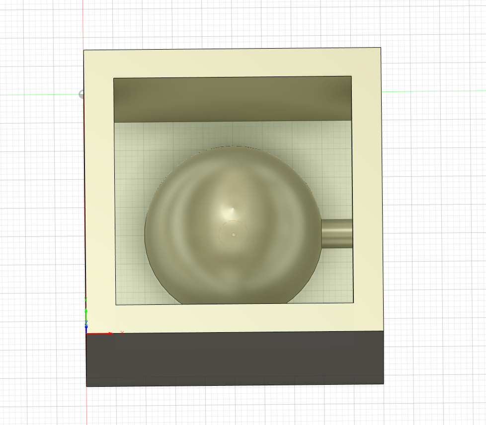
I again create a 3D pocket cut and a 3D morphed spiral cut, exported my files as .nc, started UGS, connected the machine, load the 4mm flat end and fixed a new 30mm plywood piece to my CNC-machine.
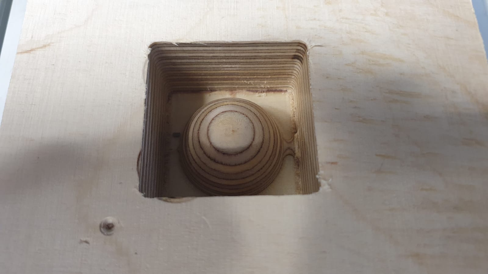
I started the rough cut and was happy to see everything working:
After that I inspected the collet a little bit more and found out that I was a dumb piece of bread...
As said before the ballpoint mill was 1/8" thick. I was thinking that if i use the 4mm collet I can thighten in up enough so that it would fit..
Found out that we had a 1/8" collet which I should have used bevore...
I switched to that, started the job and everything worked as it should!!
I will add a video later, I have to compress it first...
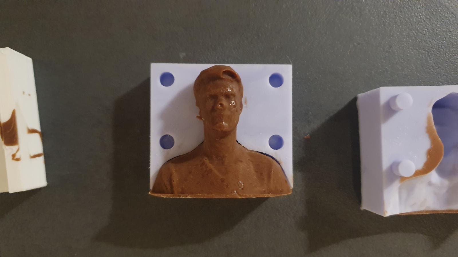
Now that I had a finished piece I went on and mixed a good amount of my food safe silicone, so mold the cutted ball and my backup plan aswell:
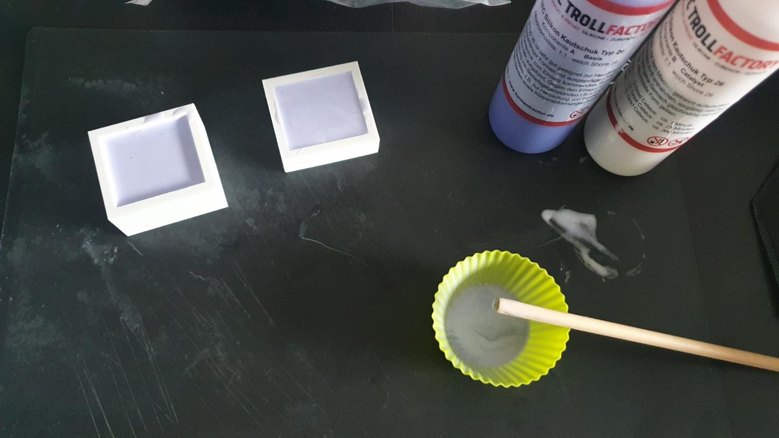
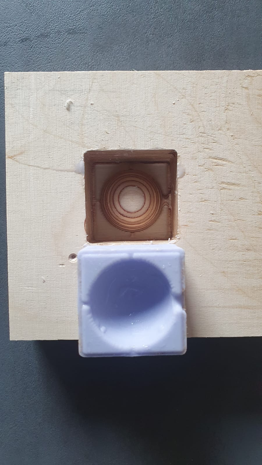
The 3D printed mold came out perfectly while the wood mold hat some small wood particles inside, so for my final chocolate moldig I used the 3D printed mold halfes...
The End.
As group assignment we had to review the safety data sheets for each of our molding and casting materials. As we all used different molding materials, I will review the saftey data for mine.
If you want to see the other materials, please visit Lana or Lars pages.
The Material I used was TFC Silicone Type 26. I used this, because it is food safe.
Here are some Data of the Material:
Color: lilac (component A) and white (component B)
Mixture: 1:1 by weight
Specific gravity: 1,25
Viscosity 5500 ± 450 mPas
Mixing time at 23 degrees Celsius 1 minute
Processing time at 23 degrees Celsius approx. 25 minutes
Curing time at 23 degrees Celsius 360 minutes
Hardness Shore A after 24 hours approx. SH 26 +/- 3
Breaking load 3.5 ± 0.2 N/mm²
Elongation at break 500 ± 20%
Tensile strength 5 ± 1 N/mm²
Reproduction detail accuracy: 2 micron
Dimensional change after 24 hours 0.02