13. NETWORKING AND COMMUNICATIONS
Individual assignment:
Design, build, and connect wired or wireless node(s) with network or bus addresses.
Group assignment:
Send a message between two projects.
ASYNCHRONOUS SERIAL COMMUNICATION WITH AT COMMANDS
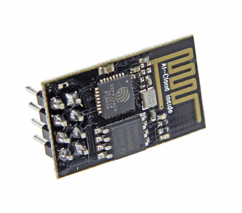
ABOUT ESP 01
The ESP8266 ESP-01 is a Wi-Fi module that allows microcontrollers access to a Wi-Fi network. This module is a self-contained SOC (System On a Chip) that doesn’t necessarily need a microcontroller to manipulate inputs and outputs as you would normally do with an Arduino, for example, because the ESP-01 acts as a small computer. Depending on the version of the ESP8266, it is possible to have up to 9 GPIOs (General Purpose Input Output). Thus, we can give a microcontroller internet access like the Wi-Fi shield does to the Arduino, or we can simply program the ESP8266 to not only have access to a Wi-Fi network, but to act as a microcontroller as well. This makes the ESP8266 very versatile, and it can save you some money and space in your projects.
INTERFACE ARDUINO WITH ESP 01
Arduino – ESP-01
RX – RX
TX – TX
GND – GND
VCC – VCC
VCC – CH_PD
None – GPIO 0
None – GPIO 2
Arduino – Arduino
Reset – GND
Note: Use the Uno as a bridge to talk to the module directly. Bypassing the Uno boot loader connecting RESET to GND.
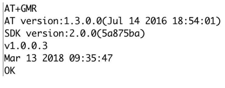
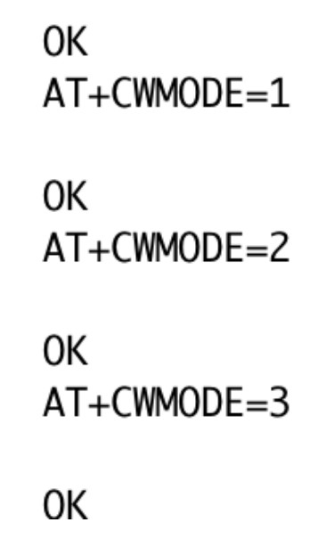
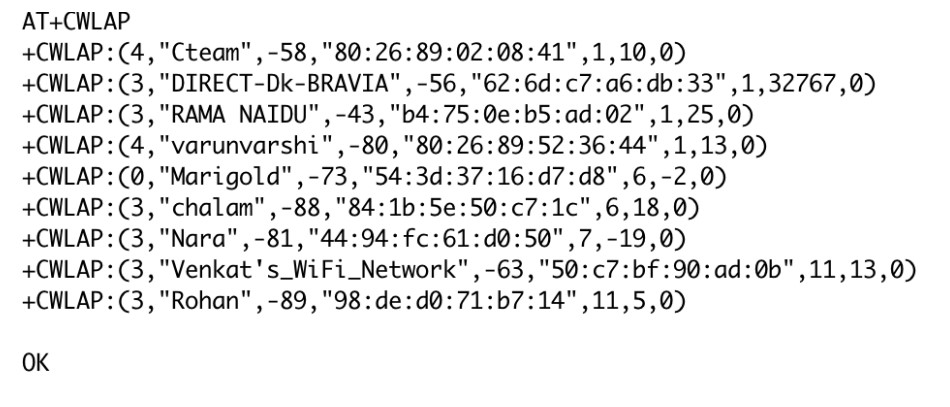
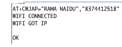
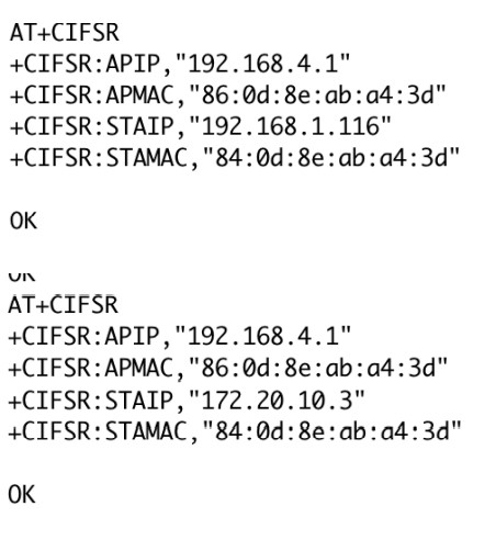
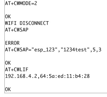
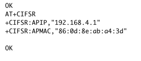
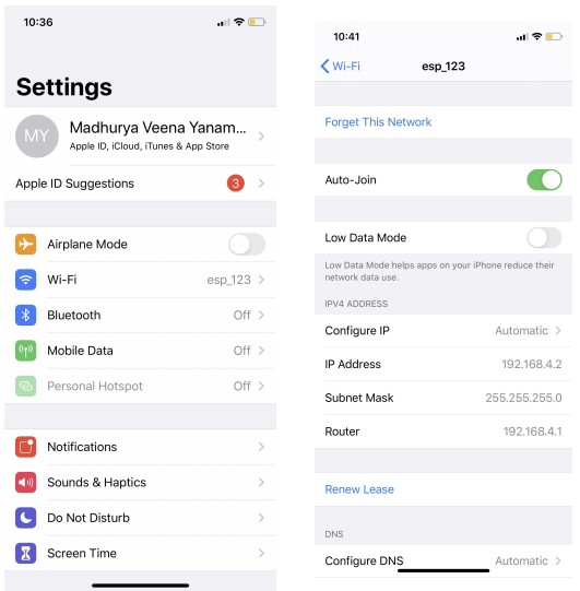
RUN AT COMMANDS TO CHECK SERIAL COMMUNICATION WITH PC
MAKING THE WIFI BOARD
I referred Neil’s hello.esp01 board to prepare my design of the board.
ESP8266 requires 3.3volts. Therefore a 3.3voltage regulator is needed for esp8266. This page has clear documentation of making a 3.3 voltage regulator for esp8266.
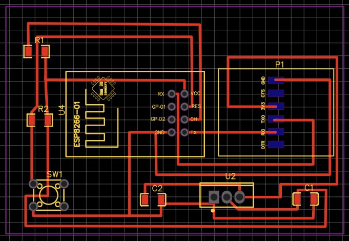
I did the design in easyEDA software.
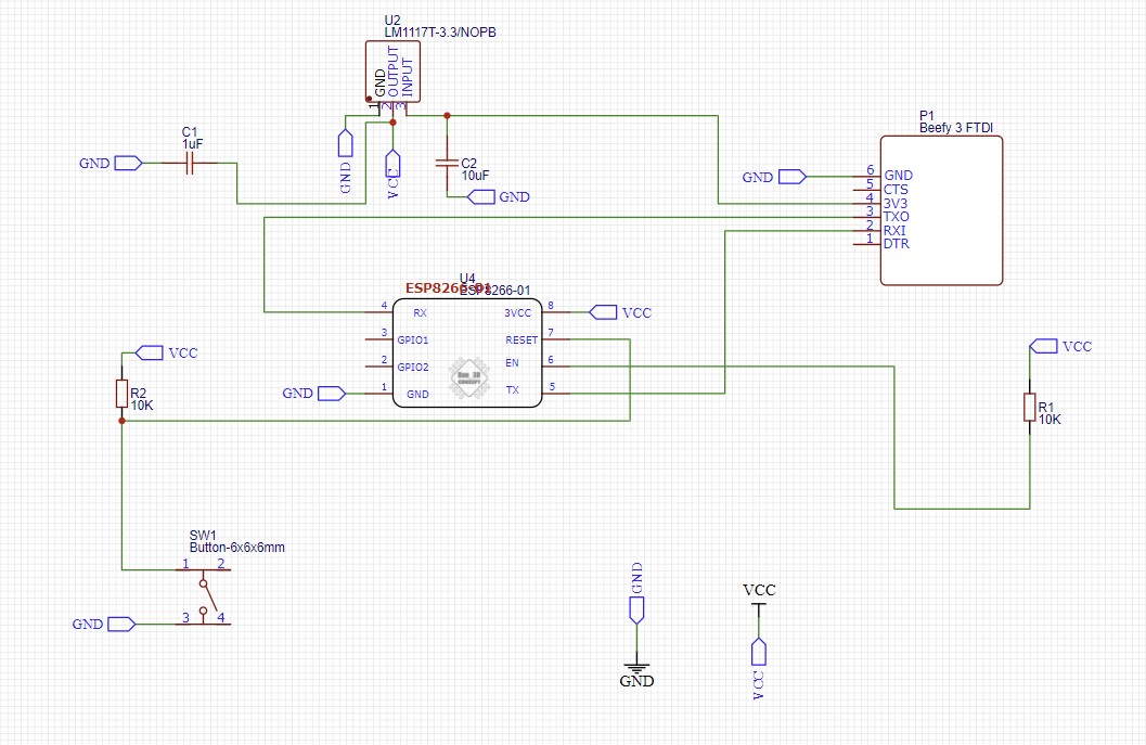
SCHEMATIC OF WIFI BOARD
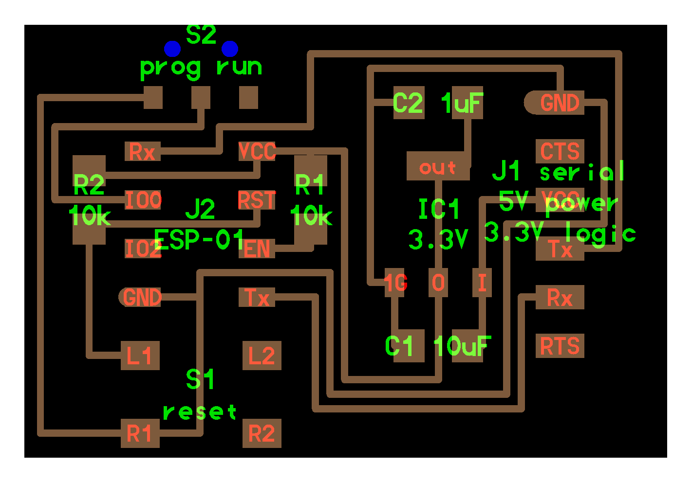
BOARD LAYOUT