10. INPUT DEVICES
Tasks for this week:
Individual assignment:
Measure something: Add a sensor to a microcontroller board that you have designed and read it.
Group assignment:
Probe an input device’s analog levels and digital signals
Microcontroller board to read sensor values
This weeks assignment is to interface a microcontroller with input devices like switches, keyboards , sensors and reading the values from it. Since, I’m new to electronics design I decided to use the Satshakit board by Danielle Ingrassia.
1.Satshakit Board
To begin with, I looked up for different satshakit board. There are many types of satshakit boards , I selected the satshakit micro board as it’s compact and perfectly fits the purpose.
What is satshakit?
Satshakit is a 100% Arduino IDE and libraries compatible, fabbable and open source board, and also an improved version of Fabkit.
Main improvements and features are:
-
16Mhz instead of 8Mhz
-
crystal instead of resonator.
-
costs less
-
100% compatible with default Arduino IDE (satshakit is recognized as Arduino UNO)
-
ADC6/7 connected instead of ADC6/7 not connected (satshakit laser and cnc)
-
larger space to easy soldering (satshakit laser and cnc)
Satshakit micro
Satshakit micro is a downsized version of the satshakit laser and cnc, developed to be used in constrained space applications like embedding the board in textiles or in small objects, or useful for who wants just a bare metal board to start with, also easy to be modified or customized. While satshakit micro is less than half the size of the other satshakits, it’s a full featured board with the full Adruino pinout, missing only the possibility to be programmed using an FTDI cable.
For more information on types of satshakit board
This page helped me in understanding more about satshakit board.
For more information on satshakit micro board
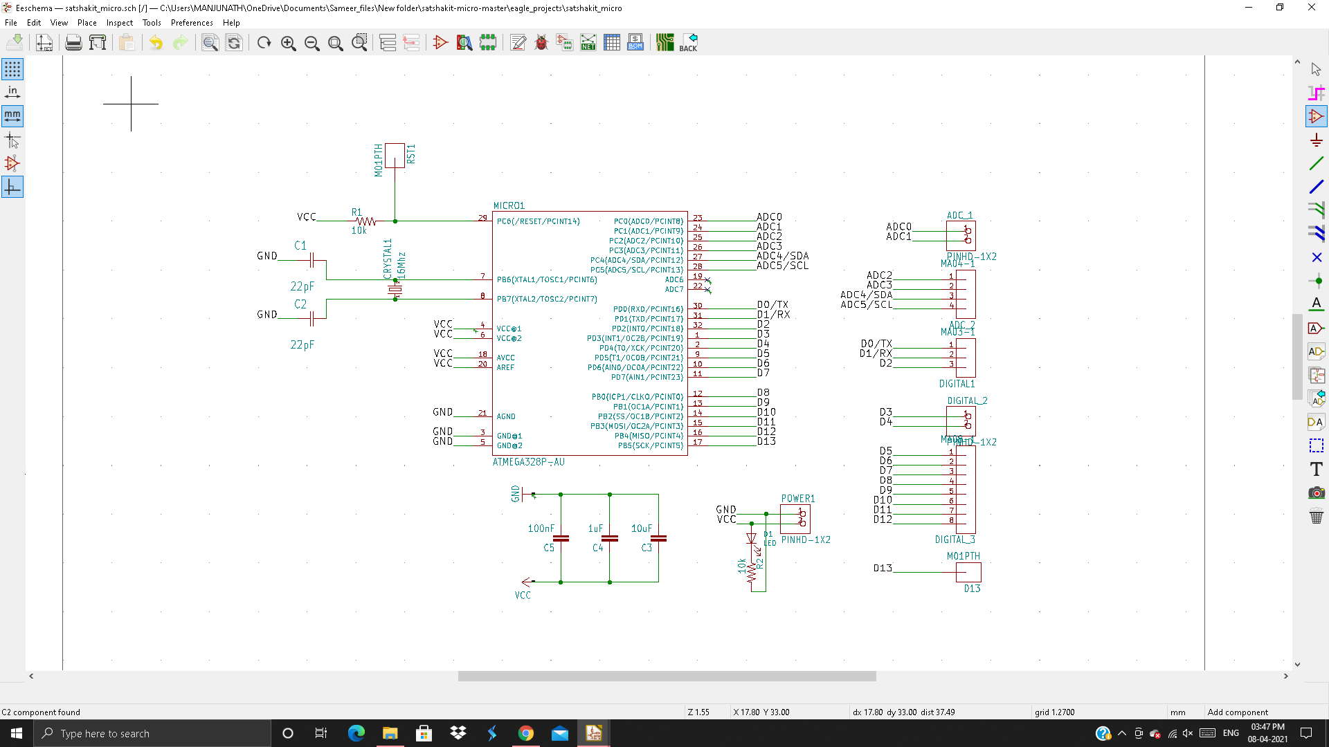
Satshakit micro board
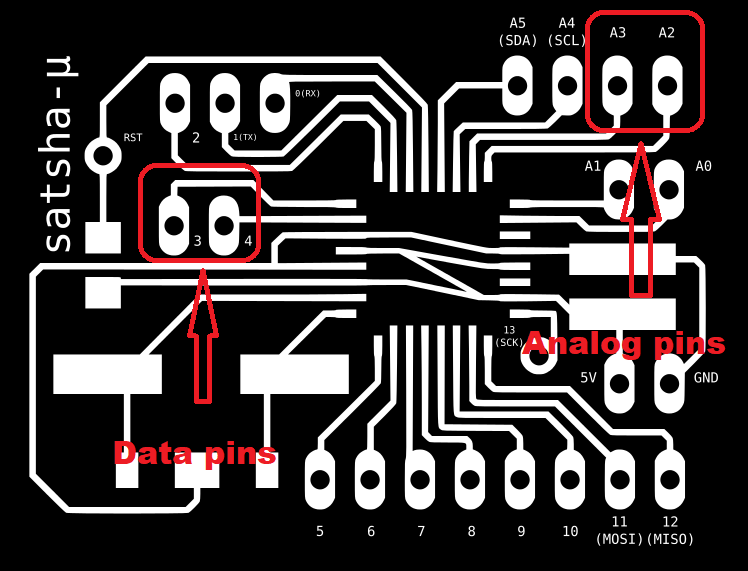
There is 13 digital pins in total and 5 analog pins , same like the arduino which is really useful to integrate sufficient sensors.
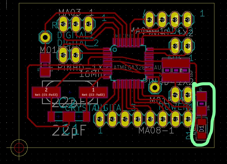
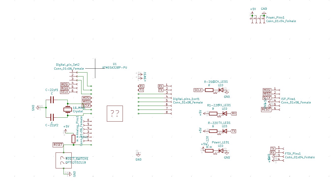
In the satshakit micro board, there is no LED to indicate the status when the board is powered on . So I included an LED and a 10K ohm resistor in the board.
Changes made to the satshakit board
The green circle indicates the changes made. Added an LED and 10K ohm resistor.
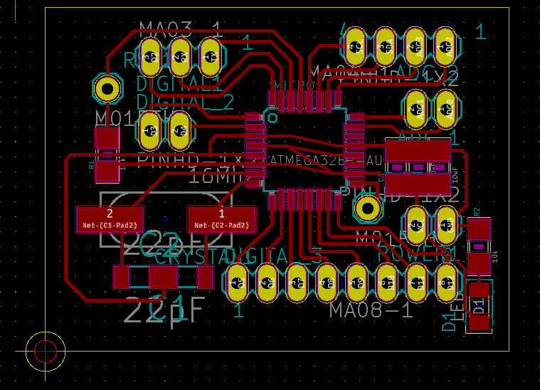
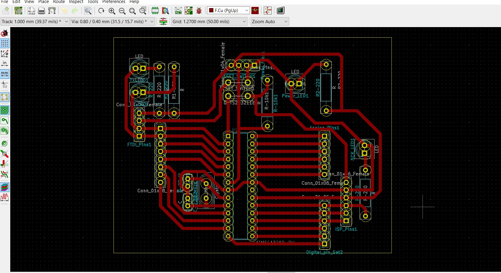
Final board design
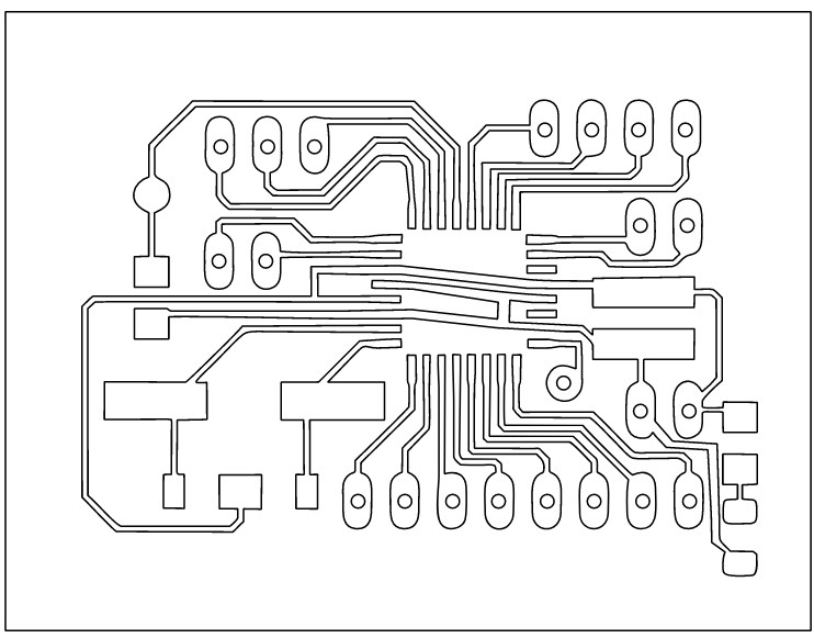
Preparing the file for milling
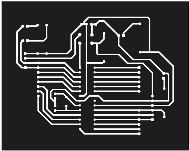
The above design was exported to DXF format in kicad. The DXF file had few breakages so I edited the file in corel draw to ensure there are no breakages.
The picture below shows the final DXF file which is ready for milling.
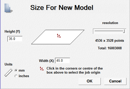
Art cam settings for milling
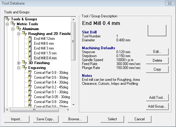
1. The DXF file is imported in artcam.
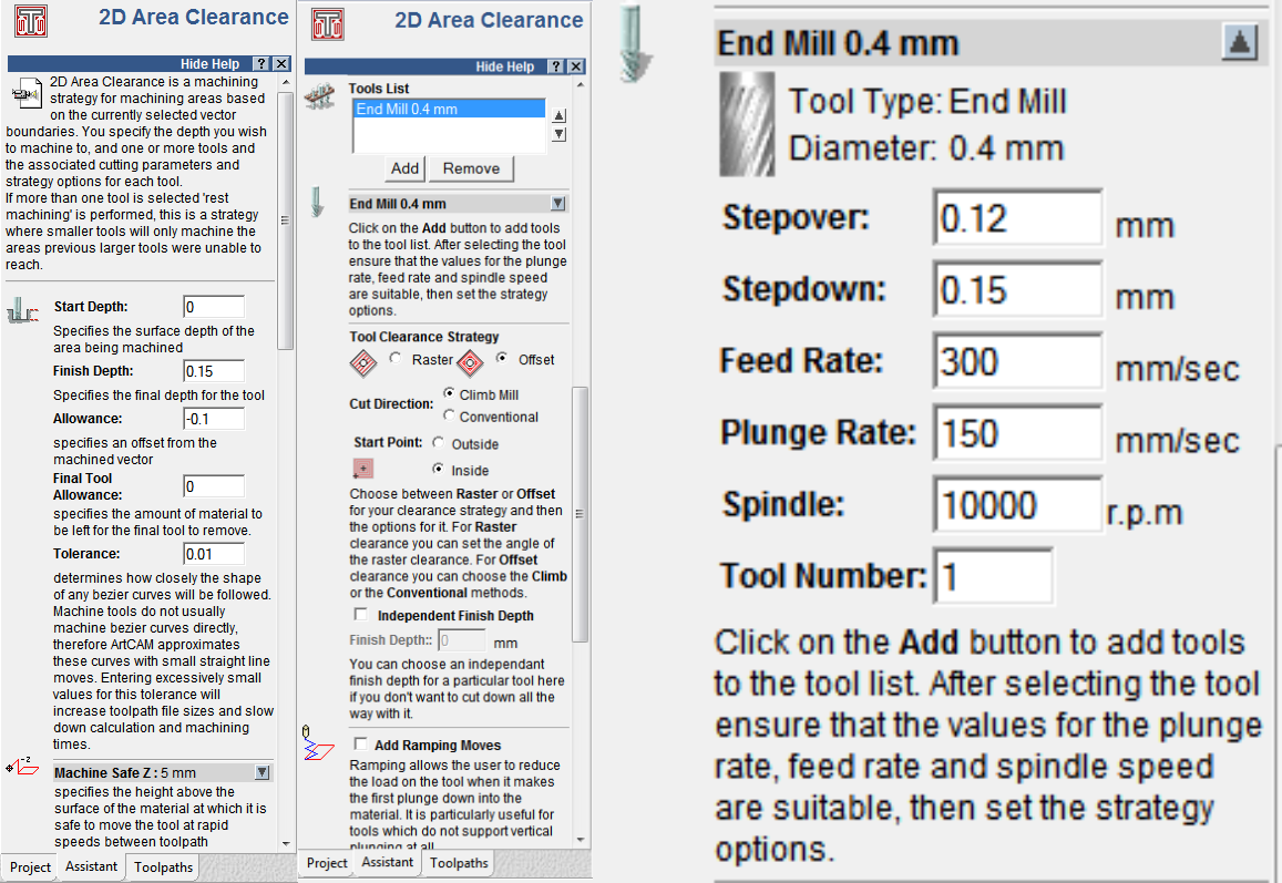
2. 2D area clearance parameters for inside traces
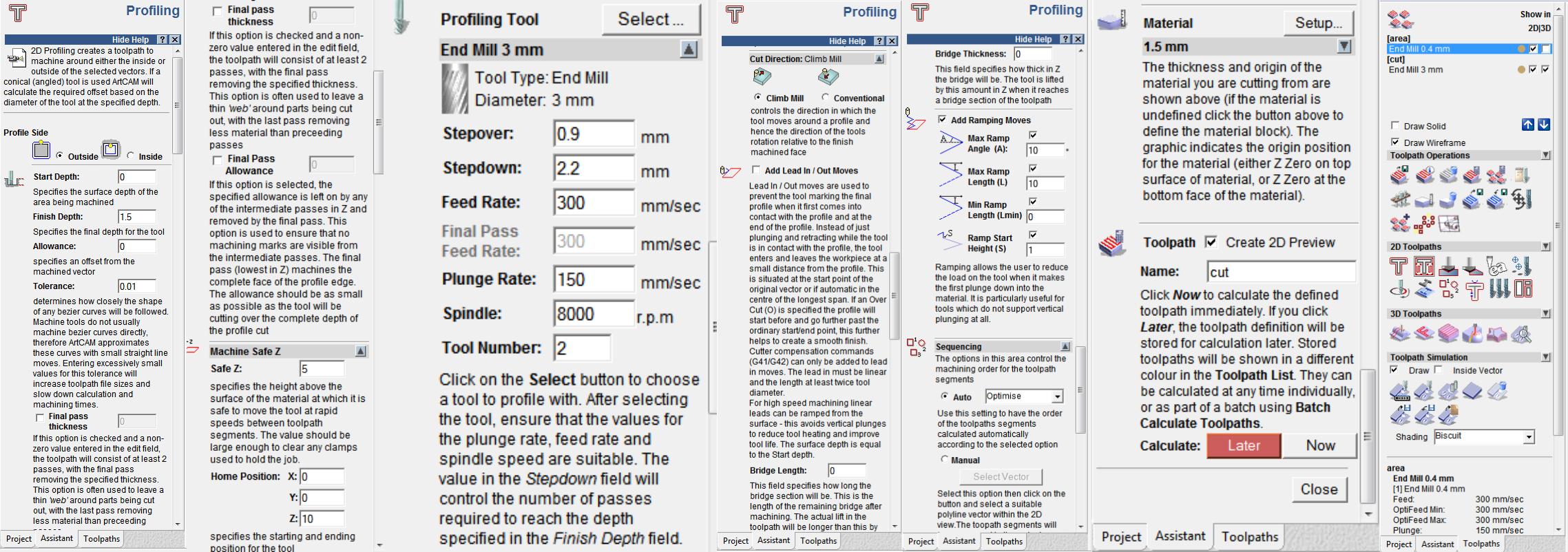
3. Profiling for outside outline cut
4. Saving the toolpath as .tap file
The toolpath for each tool should be saved separately in the preferred file location.

5. Preview of the board in art artcam

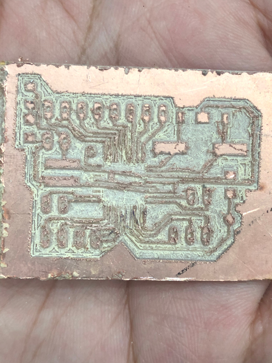
Milled board
2. Board 2
Credits : Sreedhar Ramaswamy
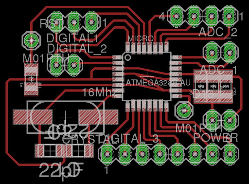
Schematic
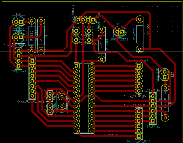
PCB design
Chemical etching method:
I tried chemical etching method for this board.
Etching is a “subtractive” method used for the production of printed circuit boards: acid or any other chemical is used to remove unwanted copper from a prefabricated laminate. This is done by applying a temporary mask that protects parts of the laminate from the acid and leaves the desired copper layer untouched.
Process
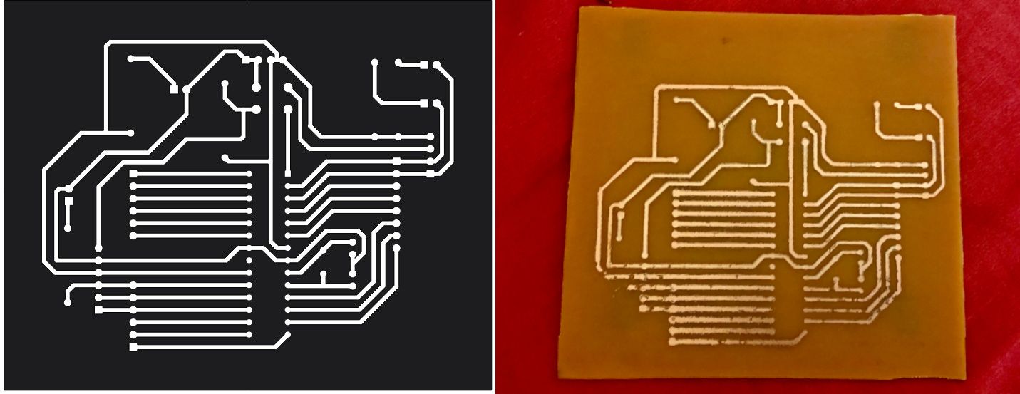
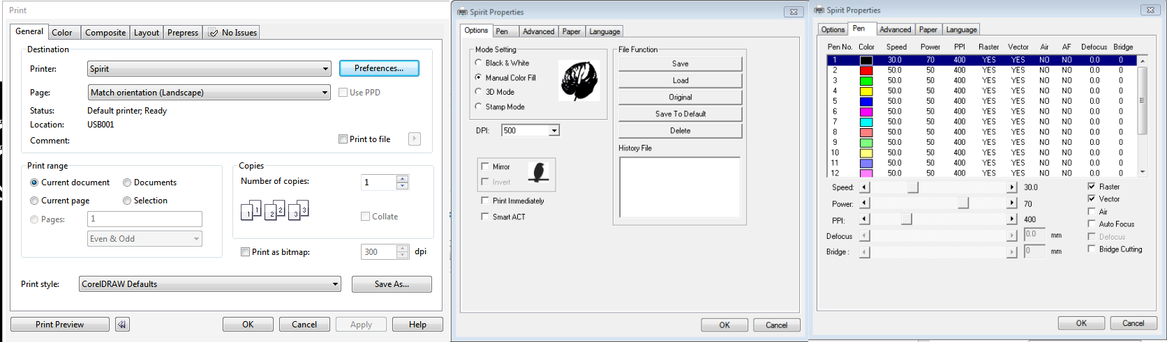
1. Preparing the file for laser cutting
The file is prepared for laser cutting in corel draw. The traces are engraved with the laser cut machine.
2. Laser cutting
- Vinyl sticker paper should be neatly pasted on copper clad material. Colin or any cleaning liquid can be sprayed on the sticker for it to stick well. Before pasting he sticker paper , the copper clad material should be cleaned with isopropyl solution.
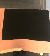
- Next, the traces are engraved in laser machine.
3. Preparing recipe for chemical etching
While using chemicals , safety is very important. Gloves is mandatory while working with chemicals.
This documentation helped me in calculating the quantity of chemicals.
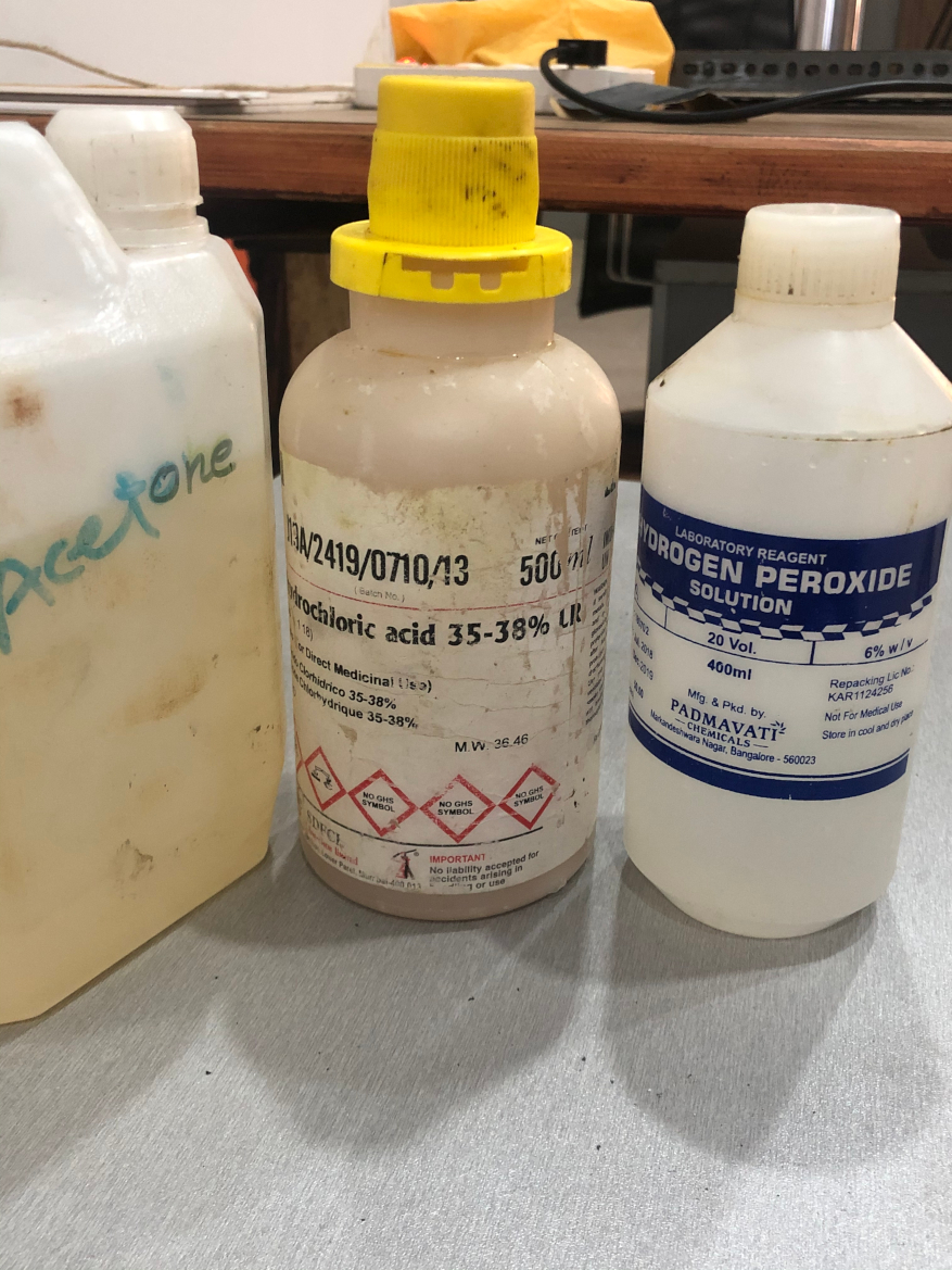
There are various ways of doing the PCB chemical etching. I used HCL and hydrogen peroxide because the reaction time is very quick with these chemicals.
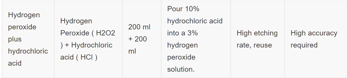
Dilution formula
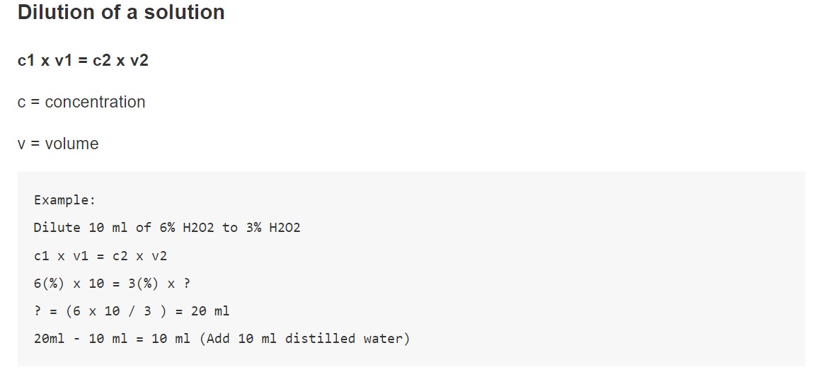
In our lab, we have 36% HCL and 6% hydrogen peroxide. Used the above formula to find the HCL and H202 volume for the above concentration. The volume of these chemicals depends on its concentration.
Calculation of HCL volume
c1 * v1 = c2 * v2
36 % * v1 = 10% * 200
v1 = 56 ml
Here, 200 ml of HCL is used for 10% concentrated HCL. For, 36% concentrated HCL 56ml of HCL should be used.
Dilution : v2 -v1 200ml - 56ml = 144 ml
Therefore, 144 ml of water should be used to dilute 56ml of HCL.
Calculation of H202 volume
c1 * v1 = c2 * v2
6 % * v1 = 3 % * 200
v1 = 100 ml
Here, 200 ml of H202 is used for 3% H202. For, 6% H202 100ml of H202 should be used.
Dilution : v2 -v1 200ml - 100ml = 100 ml
Therefore, 100 ml of water should be used to dilute 100ml of H202.
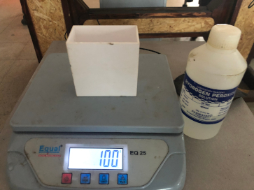
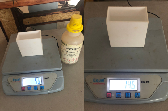
We don’t have any conical flask and measuring spoons to calculate volume in our lab. So I used the weighing scale which calculate mass.
Converting volume to weight
1 ml = 1 gram
The weighing scale should be set to tare so that it only calculates the weight of the liquid and not the container.
- H202
- HCL
4. Chemical reaction
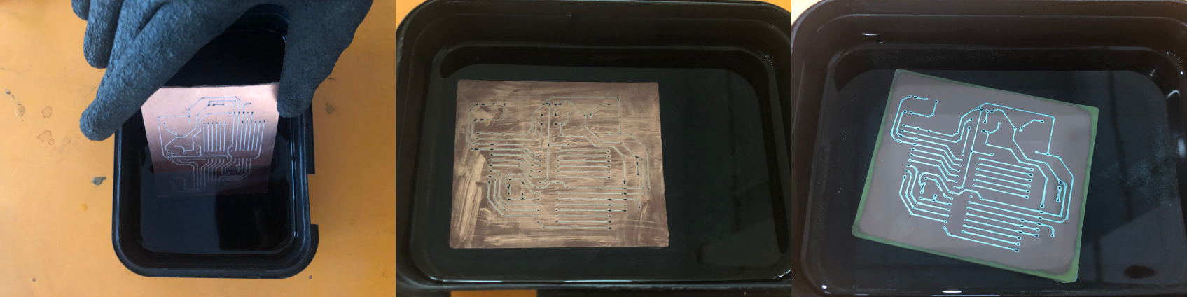
The unwanted copper is removed. The traces are protected due to the sticker.
The etching time depends on the trackwidth and the board size. This board took around 40 minutes.
The mixture should be agitated regularly every 5 minutes. This will speed up the reaction.
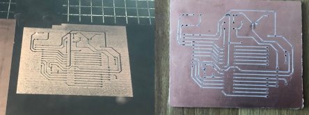
5.Removing sticker
The vinyl sticker should be removed from the traces to get the copper traces.
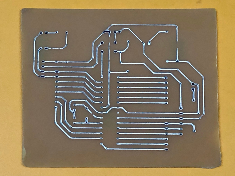
6.Board
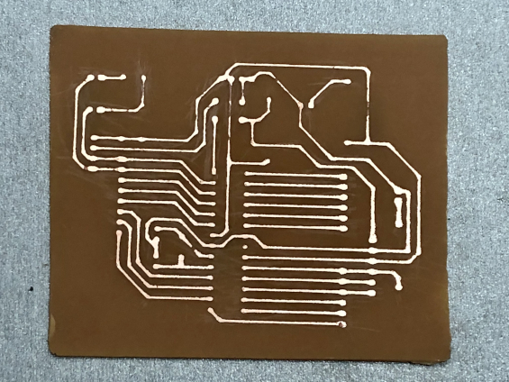
After getting the board , I realised that I need the mirrored board because the through hole components will be placed at the back of the board.
Correction