3. COMPUTER CONTROLLED CUTTING
This week , the task is to work with laser cutter and vinyl cutter.
Tasks for this week :
1] Group assignment : Characterize your laser cutter’s focus, power, speed, rate, kerf and joint clearance and types.
2] Individual assignment :
1.Cut something on the vinyl cutter.
2.Design, lasercut and document a parametric construction kit, accounting for the lasercutter kerf, which can be assembled in multiple ways.
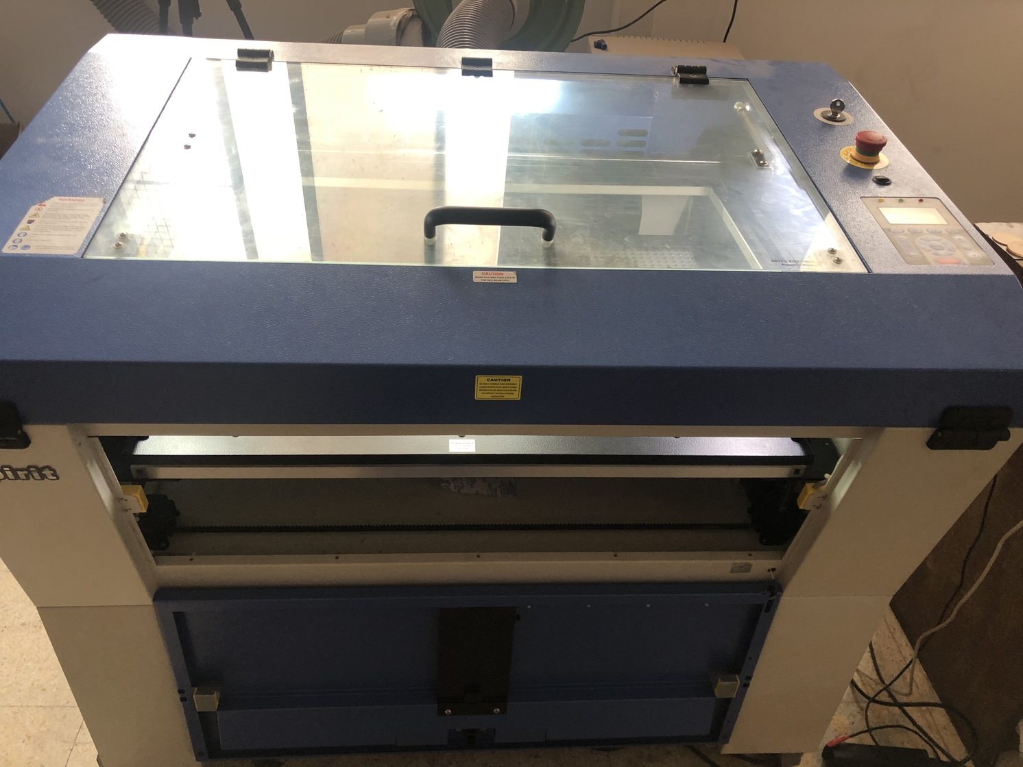
Laser cutter in my lab
The laser cutter used in our lab is GCC- Laser Pro Spirit.
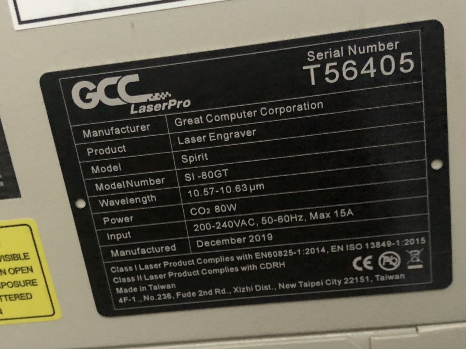
Specifications of the laser cutter
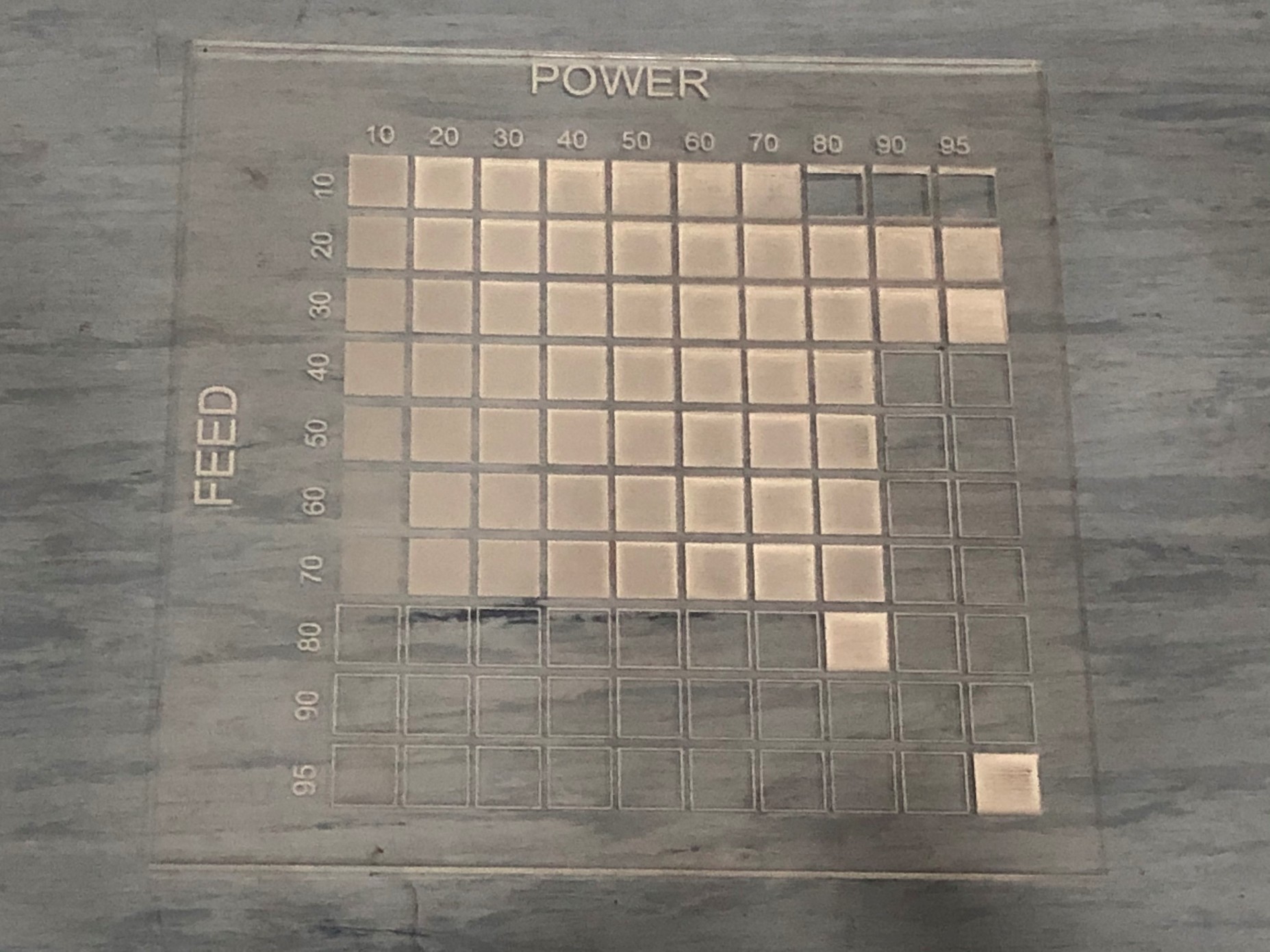
This board will help in understanding the speed and power properties of the laser cutter. The squares on the acrylic board are cut with different speed and power.
KERF
Kerf is defined as the width of the material removed by cutting process. It is important to make press fit connections. Kerf depends on the material and the thickness.
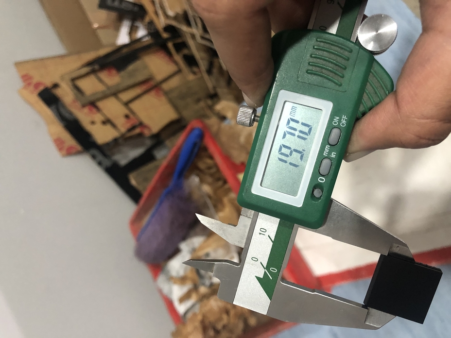
Calculating Kerf:
For finding the kerf, we made a square of 20mm by 20mm using a 2.5mm acrylic sheet. After cutting the square on the laser cutter, the measurement is 19.70mm by 19.70mm.
Thus , the material lost while cutting is 0.3mm. This represents the diameter of the laser. For CAD designs, we need to offset the lines to be cut, this represents the radius of the laser.
Kerf = diameter of laser/2
0.3/2 = 0.15mm
Calculated value of kerf = 0.15mm
I did another cut to recheck if the calculated kerf is correct. This time I wanted to cut out a 20mm square with a 10mm square inside it. Basically, the inside square dimensions should be 9.7mm after calculating the kerf. After the cut, the inside square dimensions were 9.7mm. This indicates perfect press-fit dimensions.
That means, 0.3mm material was removed and the calculated kerf i.e 0.15mm is correct.
This page explains the average kerf value for different materials.
Parts of a laser cutter -
Working of laser cutter-
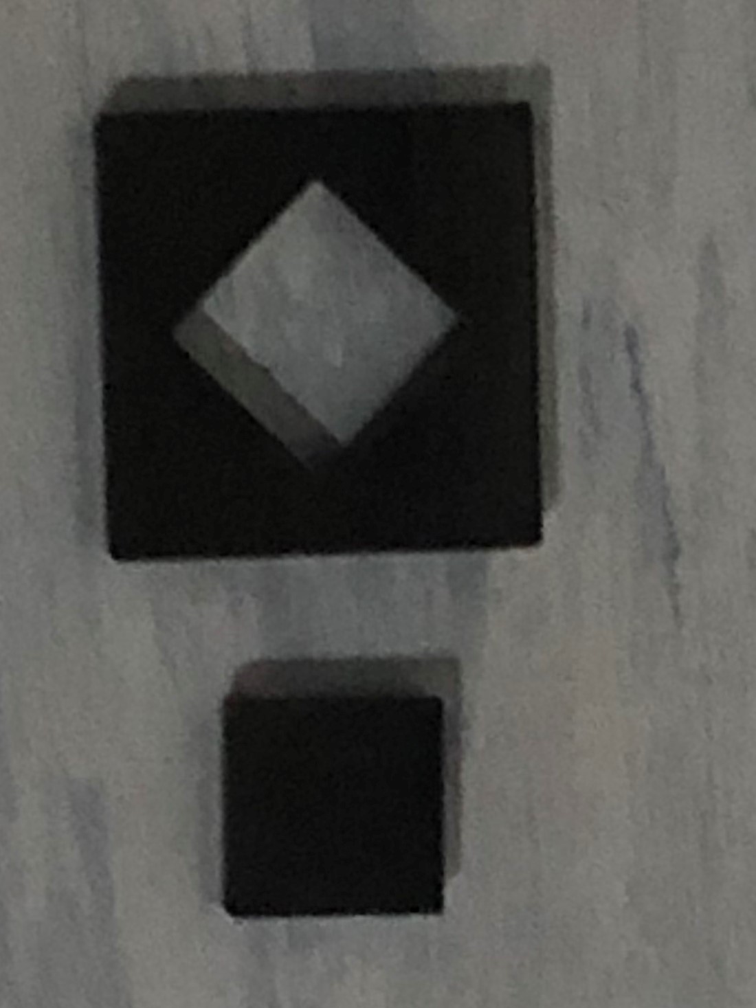
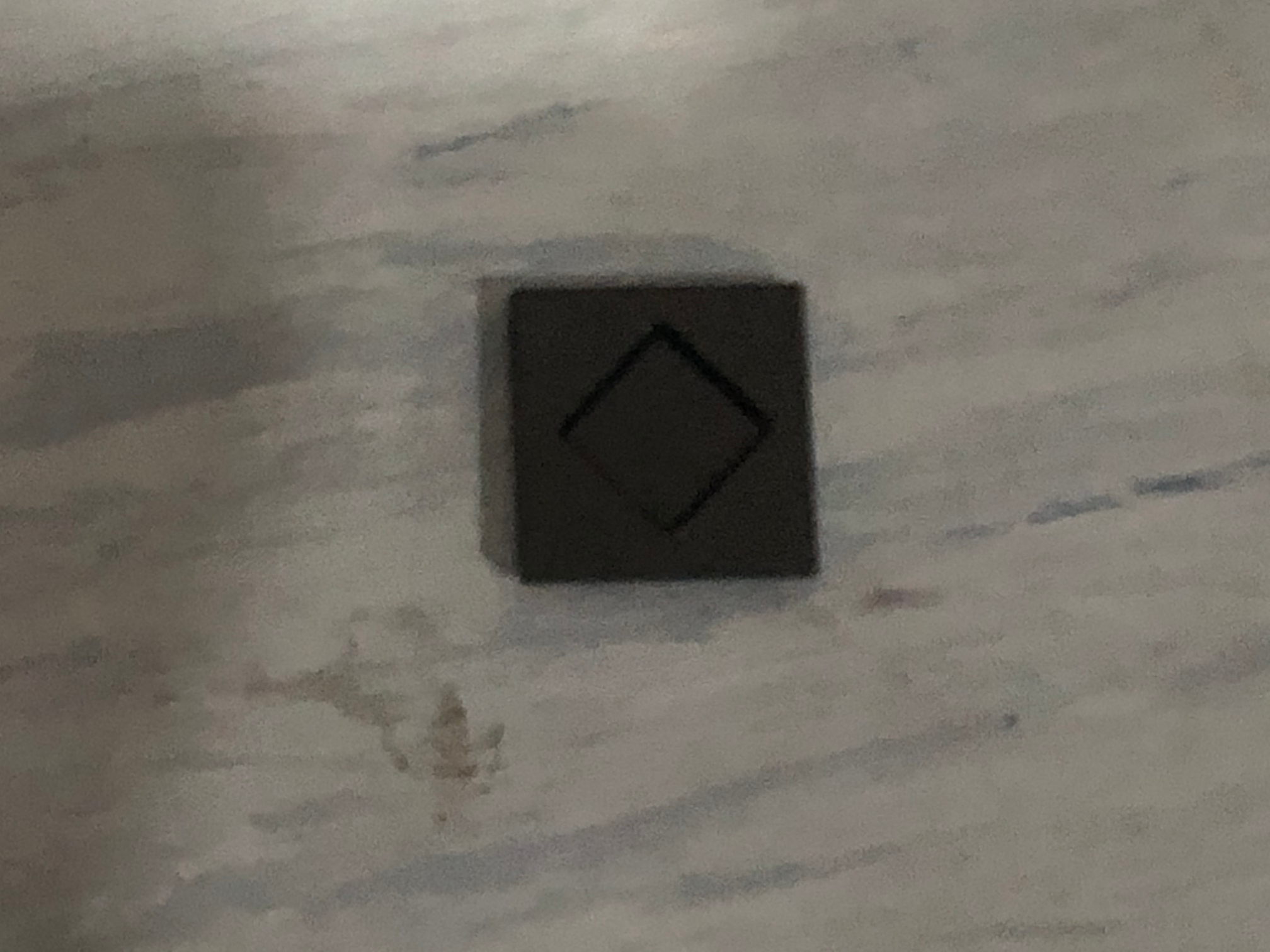
Adding and subtracting kerf for press fit connections.
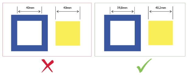
1] The kerf should be subtracted from the actual dimension [in this case 40mm] when the hole is being created in the material. This is because laser removes material while cutting and the hole becomes big.
The correct dimension for making press-fit connection would be 39.8mm. After laser cutting, the laser removes 0.2mm [0.1 kerf on both side] material. The final dimension of the inside square would be 40mm after the cut.
2] However, in the solid yellow square [ as shown above] the kerf should be added [40 + (0.1 +0.1) = 40.2mm] because , the laser removes material and makes the sqaure smaller. The final dimension of this square after the cut is 40mm.
PARAMETRIC CONSTRUCTION KIT
This page explains the uses and benefits of parametric design.
Design
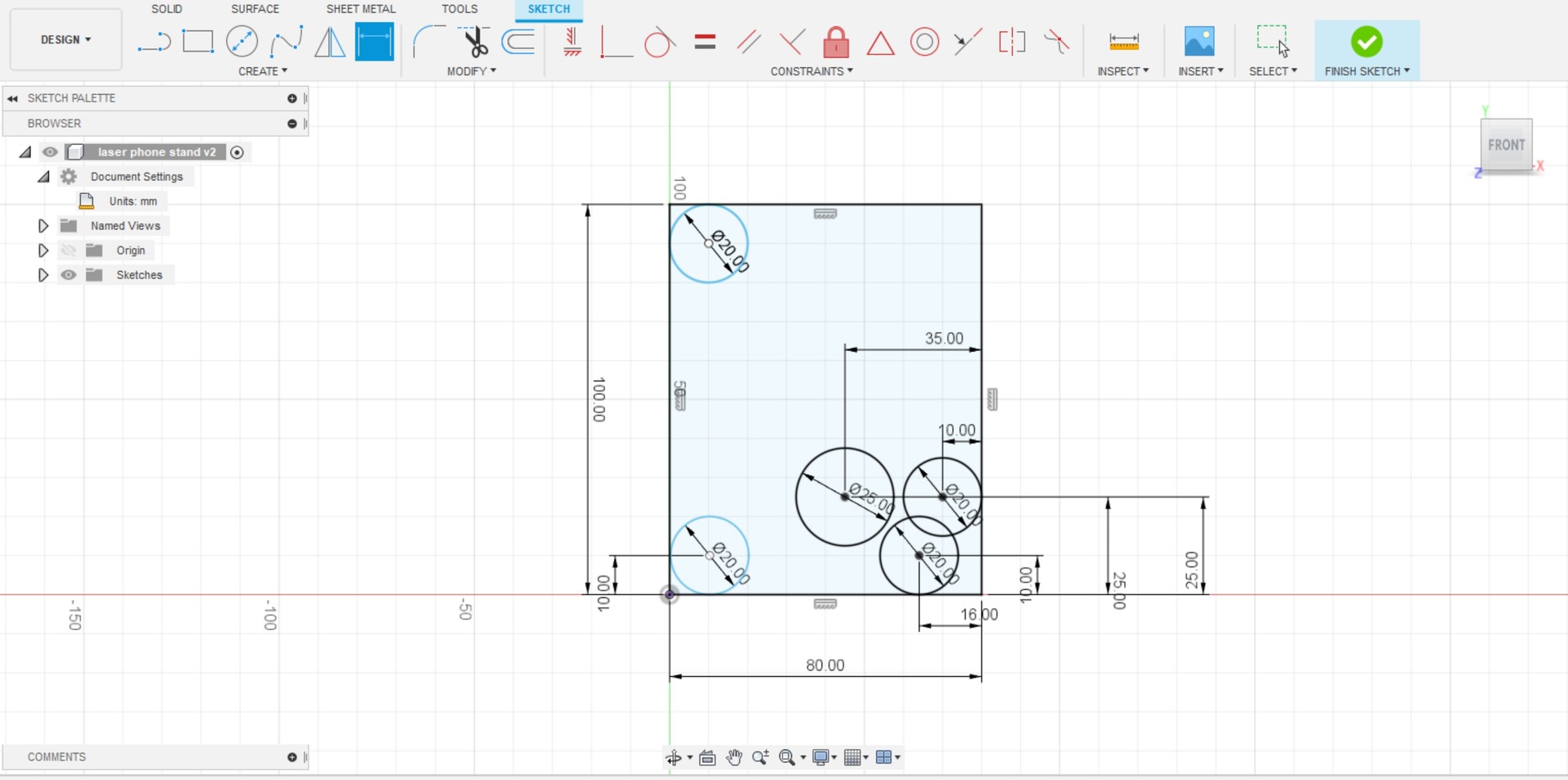
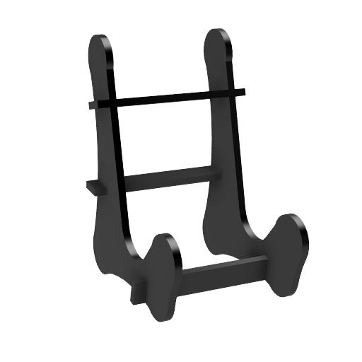
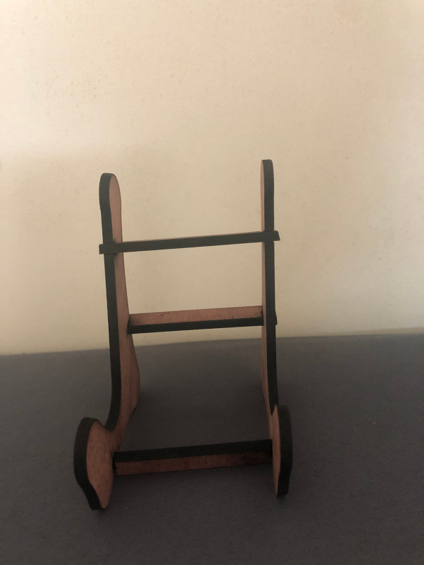
I designed a parametric phone stand in fusion 360.
1] Creating the sketch of the phone stand side in fusion 360
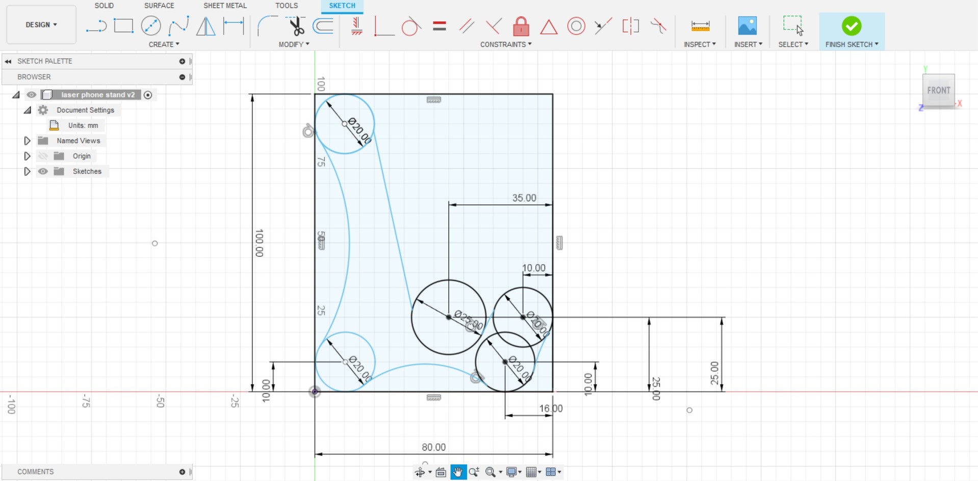
2] Brace of phone stand
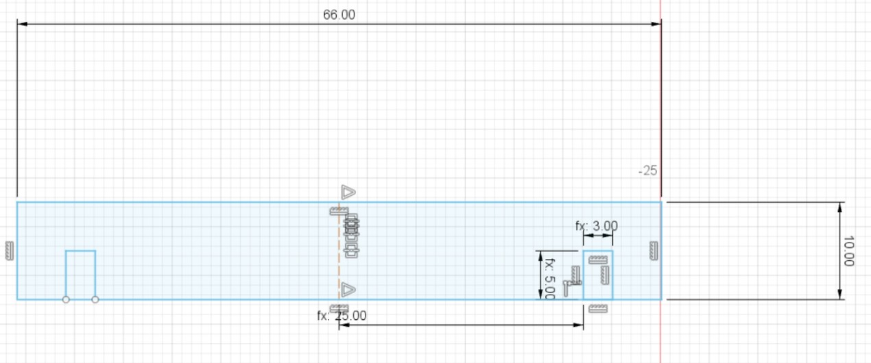
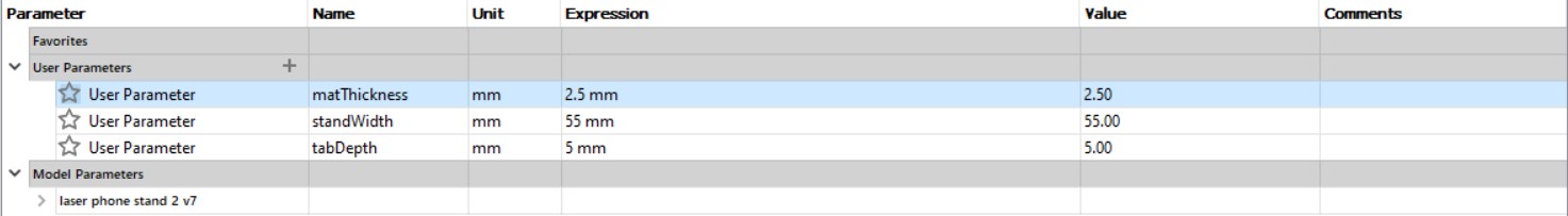
Parameters
While extruding the sketch, I realised that the 2nd tab was closed. There was some error in the extrusion.
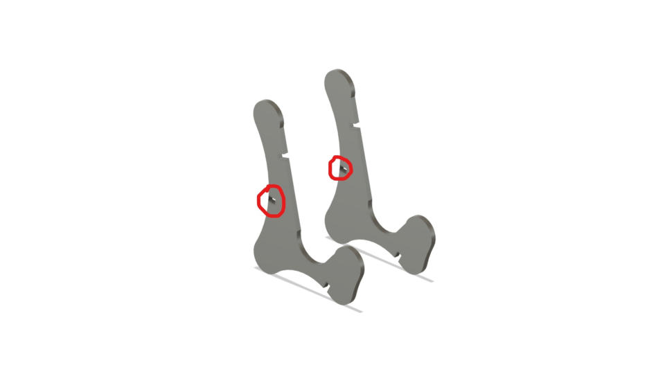
Later, I corrected the design
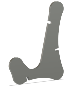
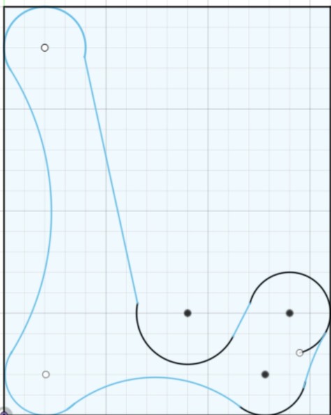
Final design
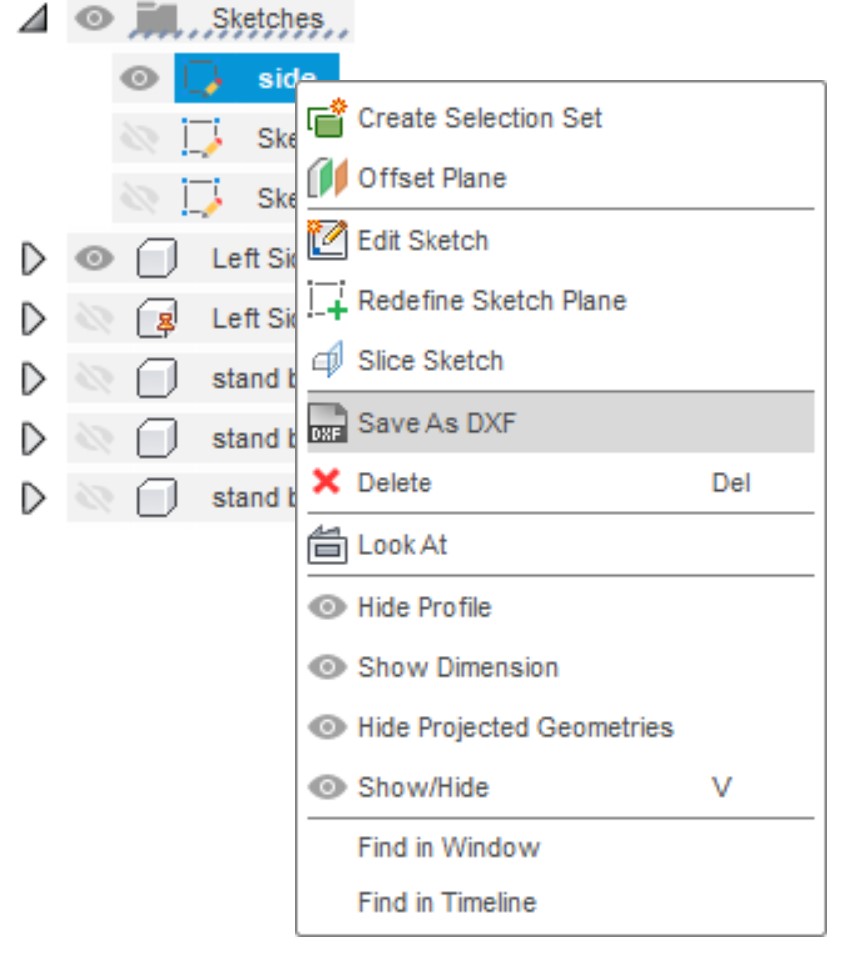
Exporting as DXF
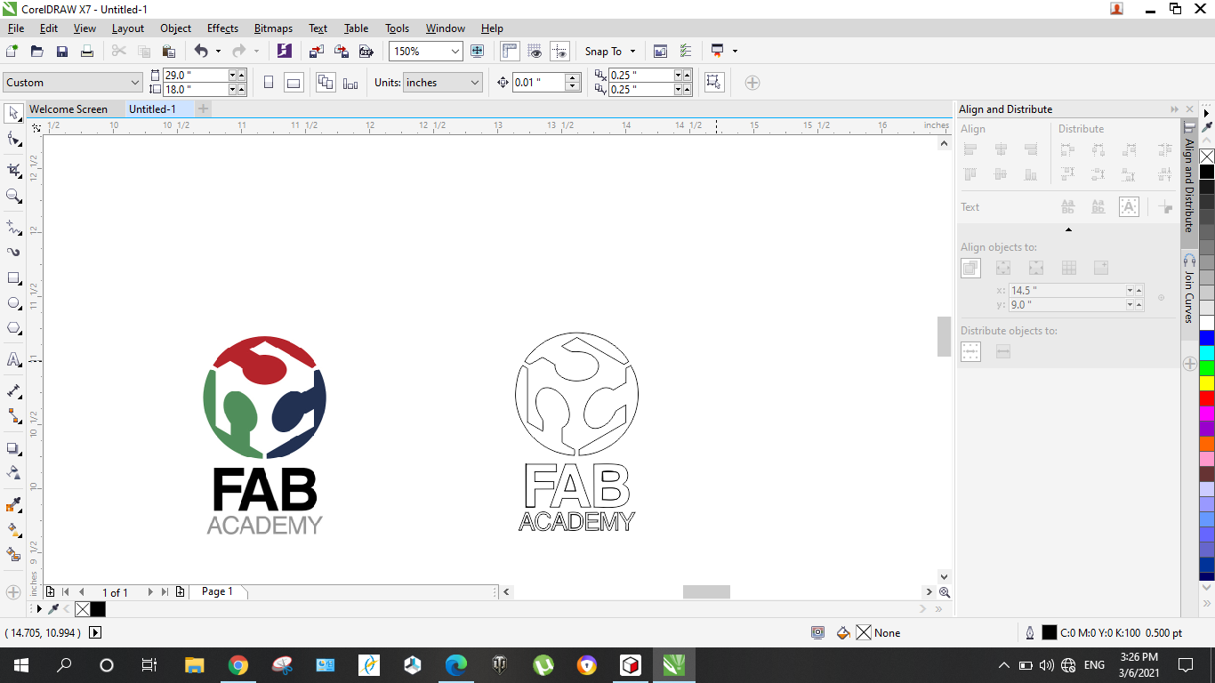
Nesting in Corel Draw

Acrylic phone stand
I cut out the design with a 2.5mm acrylic sheet.
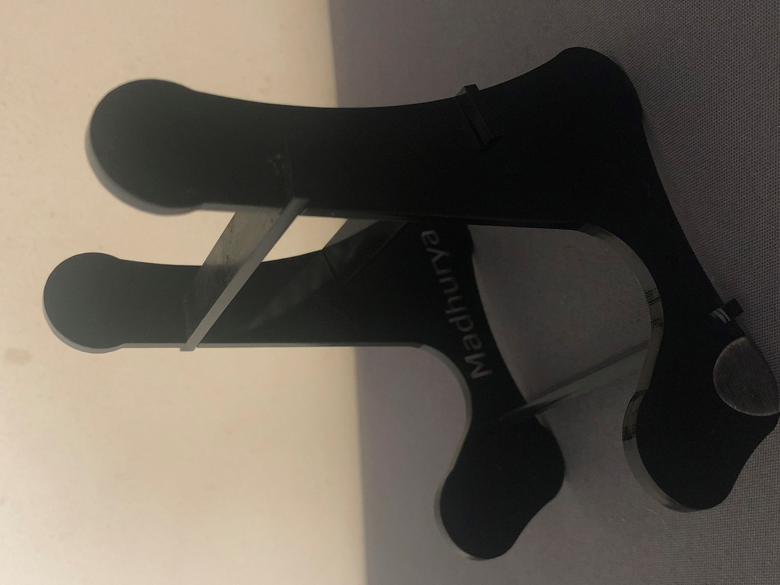
The brace was slightly loose when I cut out my design. I reiterated it by including the kerf values in the parameters.
For press fit connections:
The following parameters was changed in the design.
1.Material thickness =
Actual material thickness - kerf on 2 sides
2.5 - (0.15+0.15) = 2.20mm
2.Tab depth =
depth - kerf on one side
5 -0.15 = 4.85mm
3.Brace width : 55mm
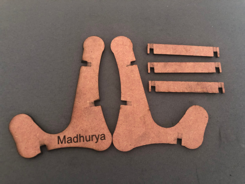
MDF phone stand
VINYL CUTTING
Step 1: Creating the vector trace
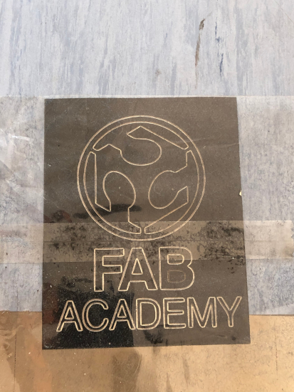
Step 2: Cut out sticker

Step 3: Removing the cut out
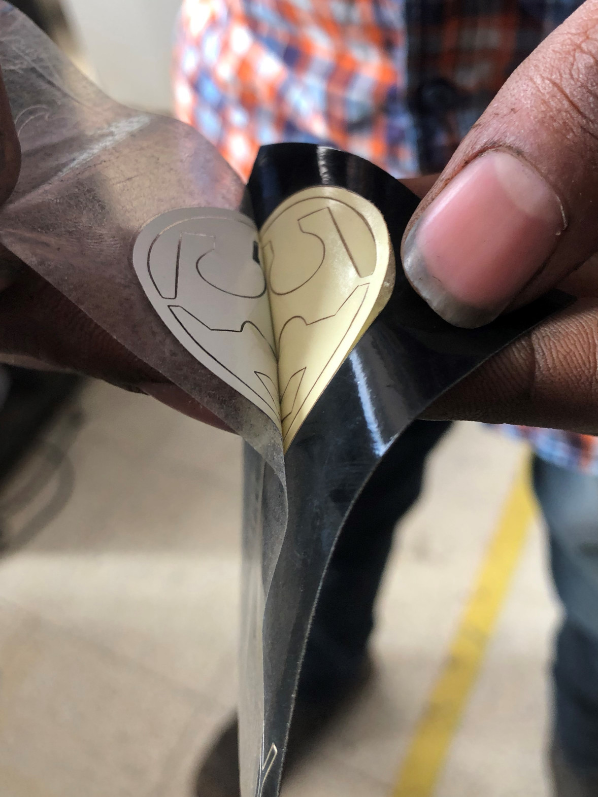
Final sticker