8. Computer controlled machining
Group assignment:
- test runout, alignment, speeds, feeds, and toolpaths for your machine
The members of the group:
- Achille Achille’s site
- Anssi Anssi’s site
- Jari Jari’s site
- Hannu
Individual assignment:
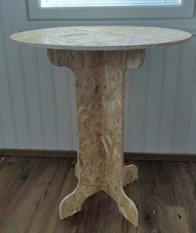
make (design+mill+assemble) something big
Idea
I struggled a long time to generate an idea of individual assignment - make something big. Material was Oriented strand board (OSB). What something big could be? Useful? Yes, I hoped so. Could be furniture?
First the all I decided use Autodesk Fusion360, because with Fusion I was able to make CAD and CAM design.
Plan to workflow
- Research
- CAD design
- CAM design
- Parts fabrication - Milling
- Assembling
- Conclusion
Research
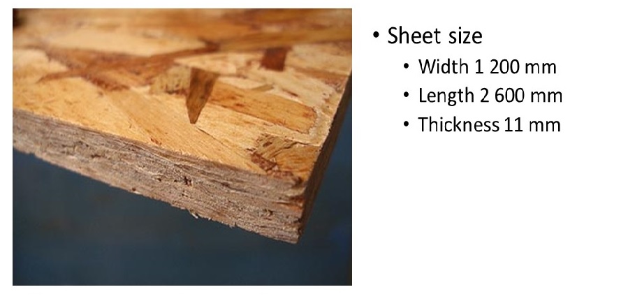
Oriented strand board (OSB) is cheap material to experiment milling technique.
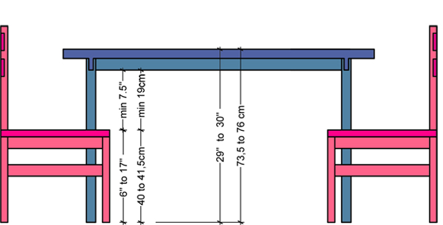
I have to find out what are dimensions of table, I found many sites. I decided use standard measurements of table,.
http://www.decosoup.com/knowhow/1389-dining-table-height-a-dining-chair-height. I decided that height of table could be about 75 cm and diameter of table about 65 cm.
CAD design
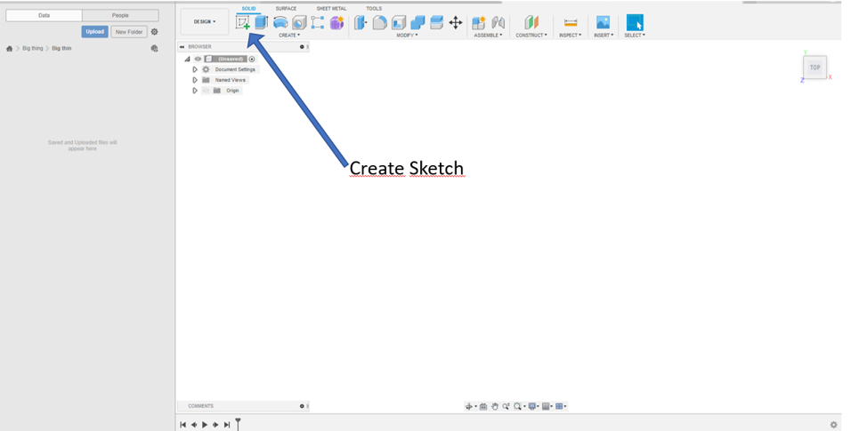
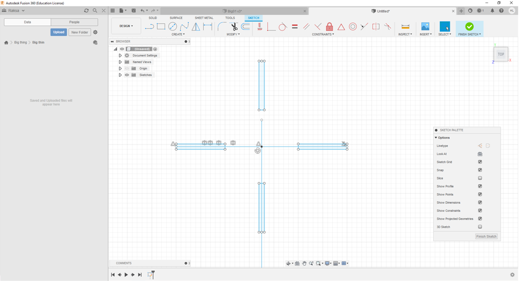
Step 1. First I open Fusion360 and I start to greate sketch by click Create Sketch button and I chose x-y surface (top).
Step 2. Then I start to draw a leg of table by line command.
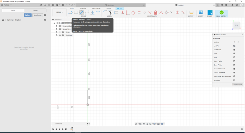
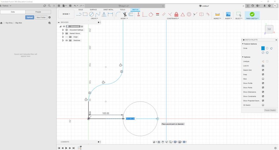
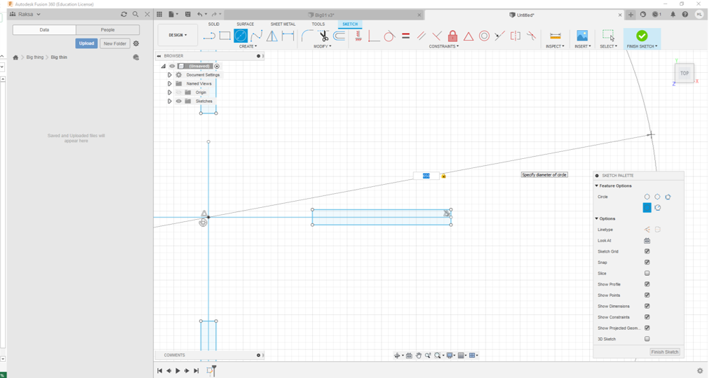
Step 3. Then I used circle command.
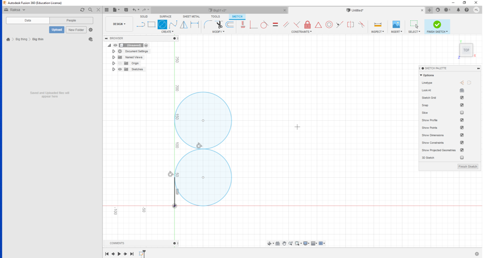
Step 4. After that I used again line command.
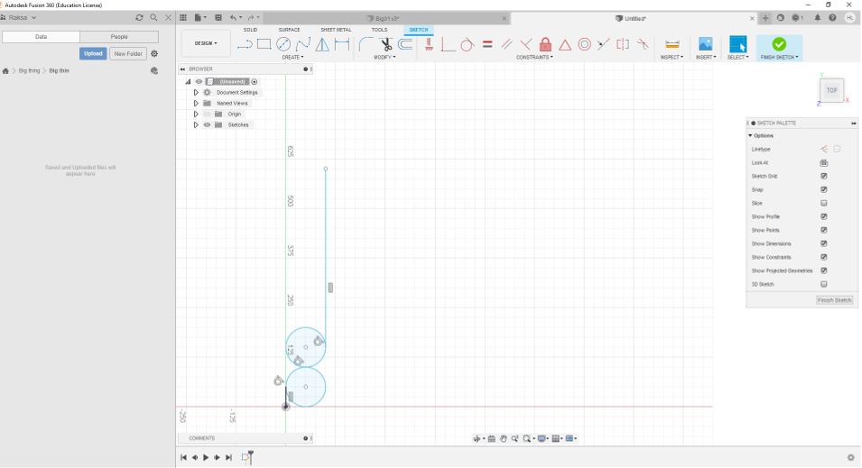
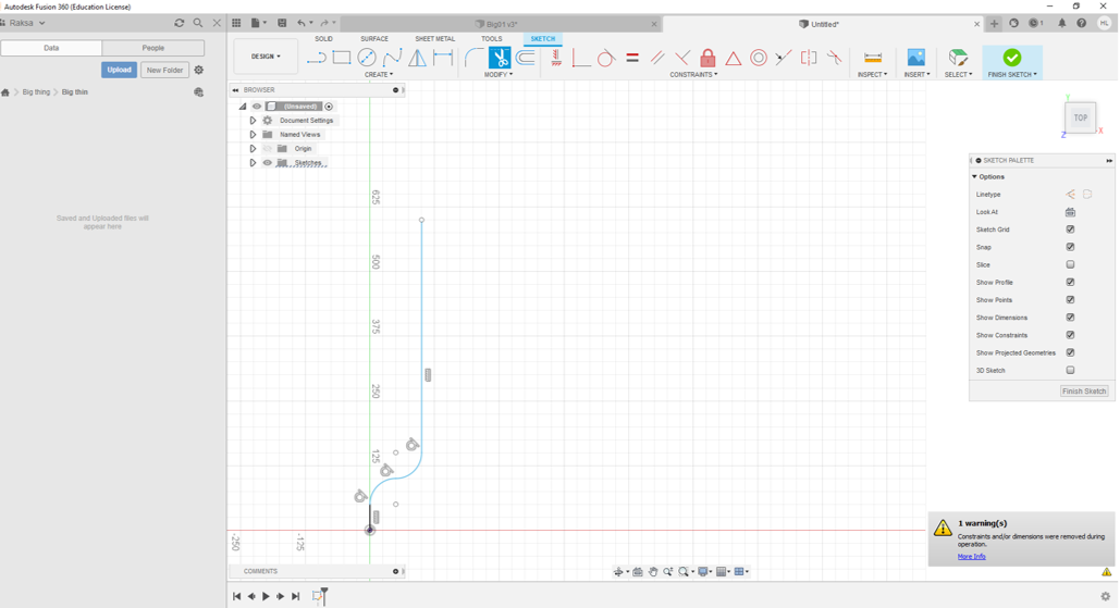
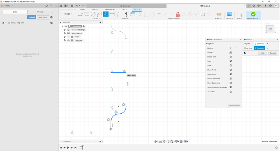
Step 5. Then I used Trim command to cut circles.
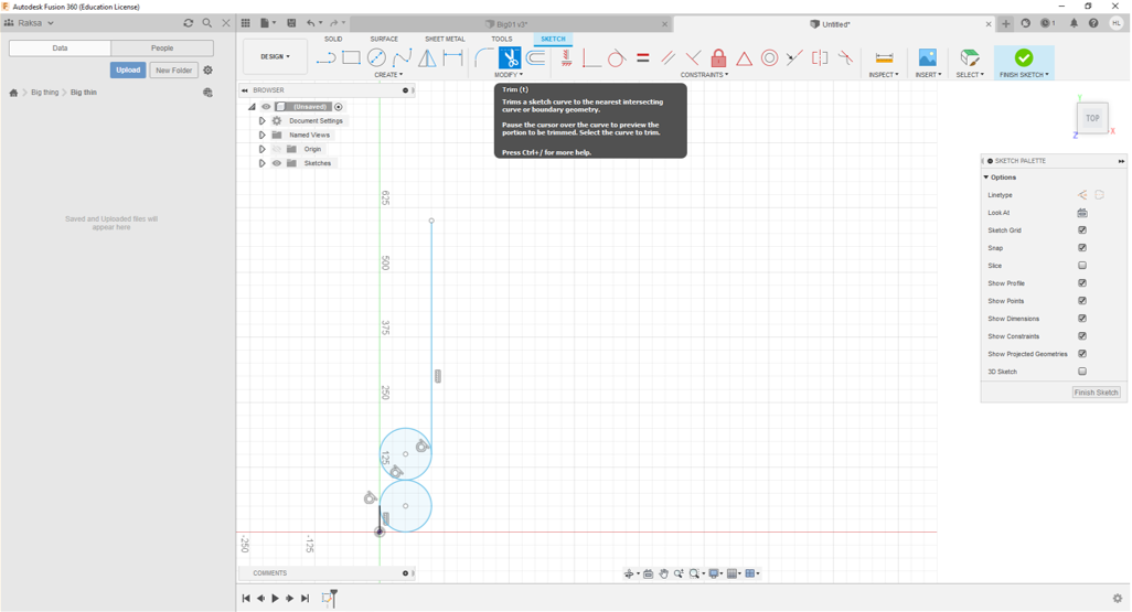
Step 6. After that the leg of the table got curved shapes
Step 7. Then I copy shape above by using mirror command.
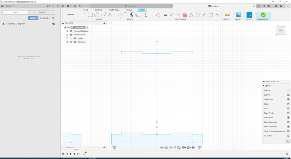
Step 8. Then I drew the rest of left side of the leg same way.
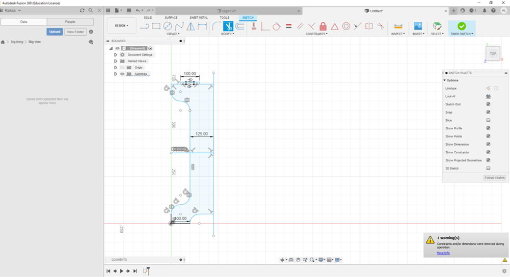
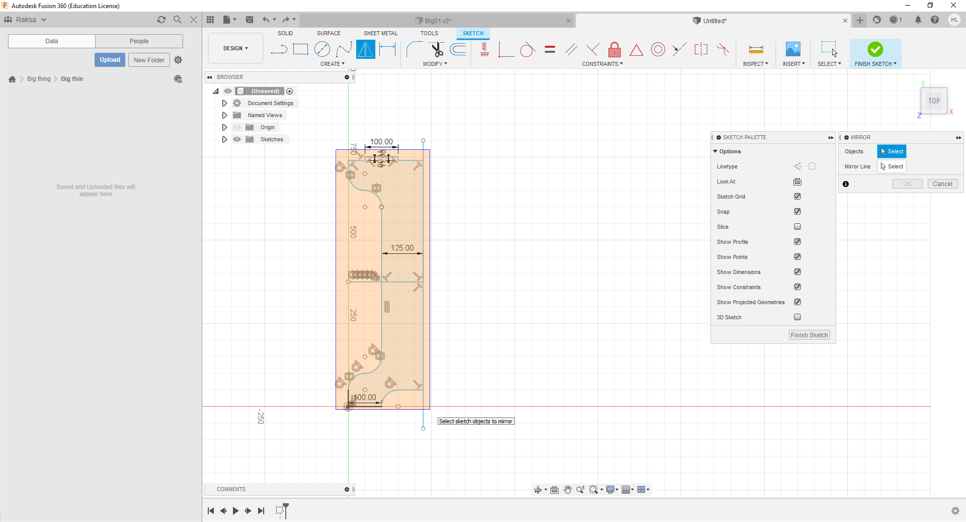
Step 9. When the left side of the leg was ready I used mirror command to create right side.
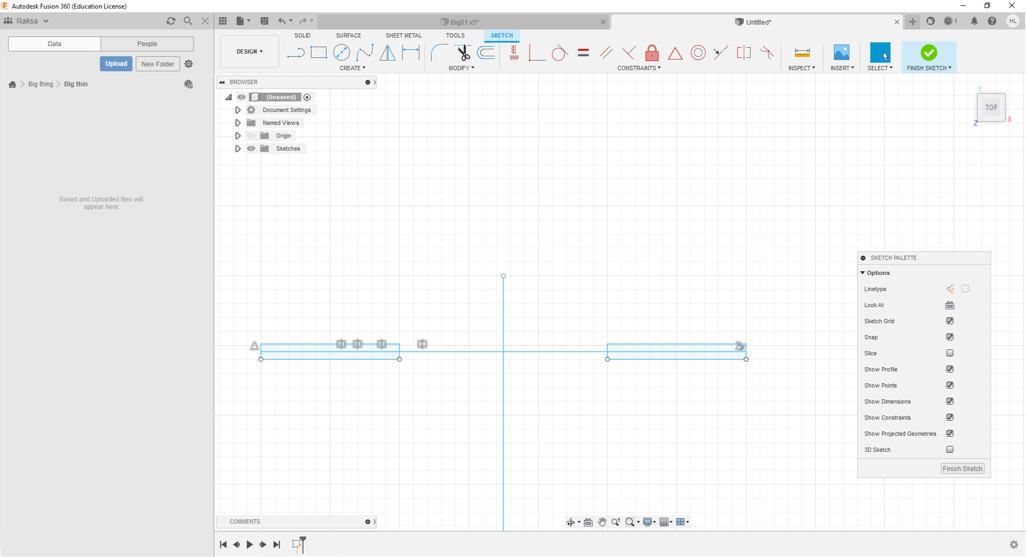
Step 10. Then I copied leg sketch by using copy command.
Step 11. Then I copy joint sketch above and designed joint holes in top plate.
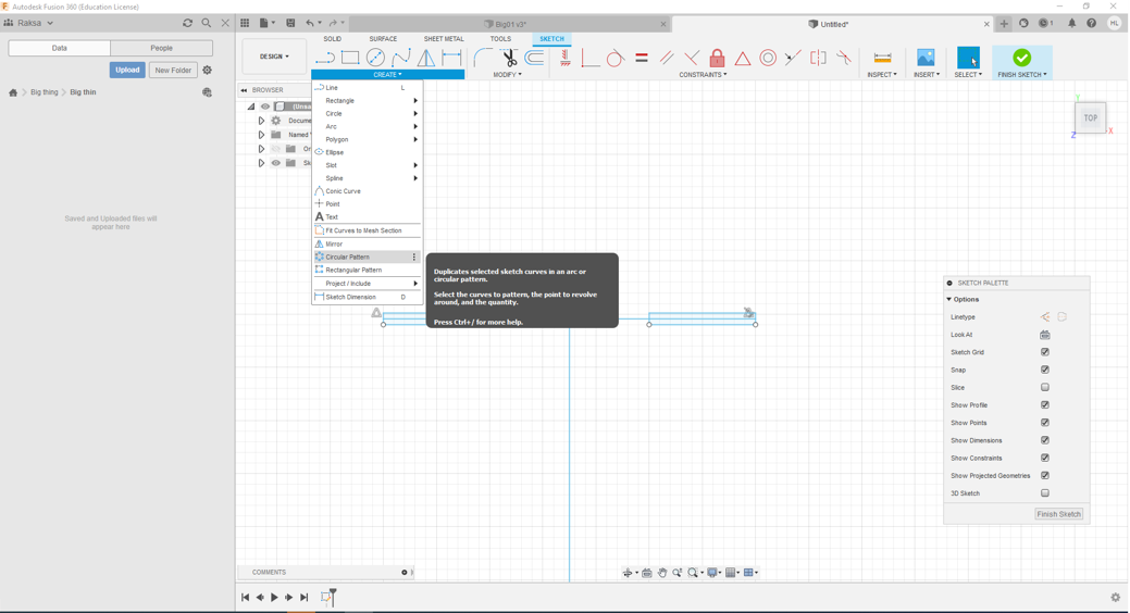
Step 12. Then I copy two holes to using Circular Pattern command
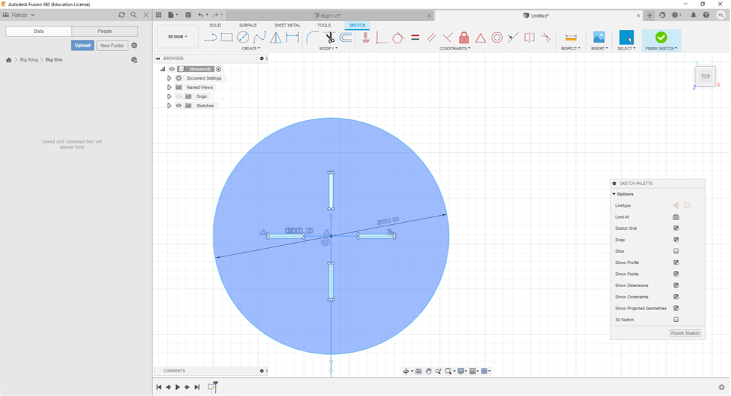
Step 13. Then I drew circle of top.
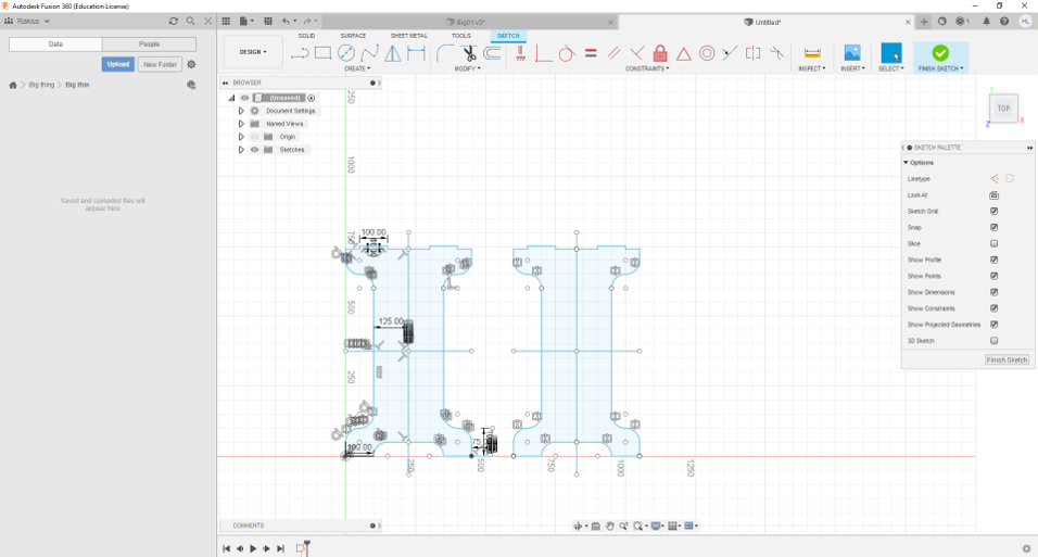
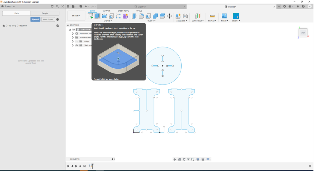
Step 14. At last I got the all sketches of the parts of table.
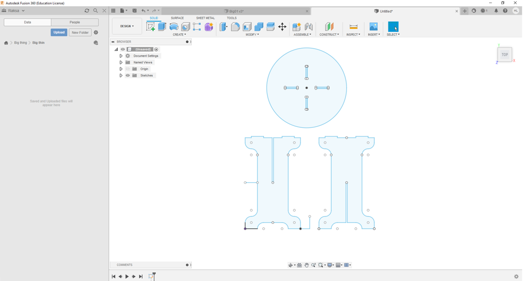
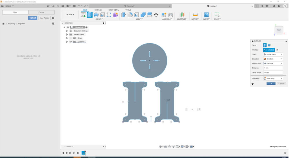
Step 15. Then I defined depth to sketch profiles by using Extrude command
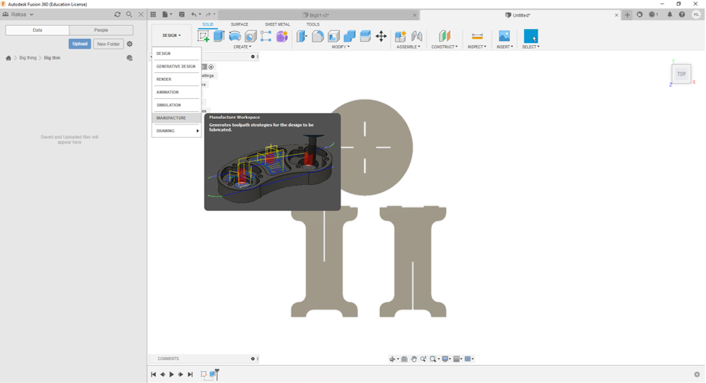
CAM design
Step 1. I chosen Manufacture to make CAM code.
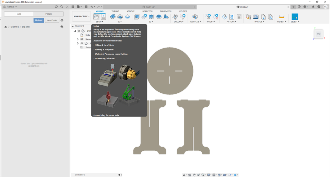
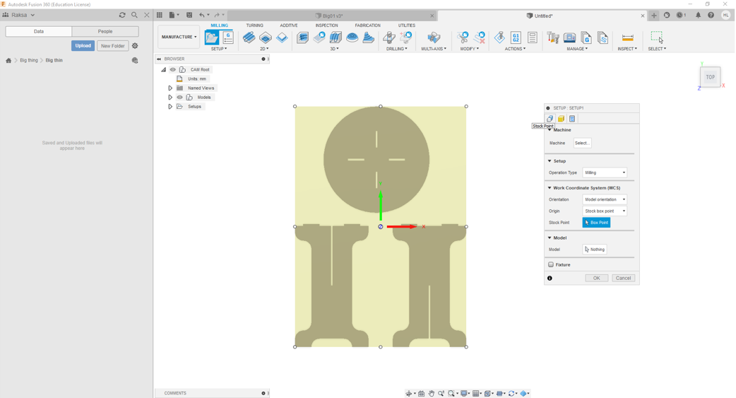
Step 2. Then I started to define Milling setup data by click Setup command.
Step 3. First I defined Stock Point. Default position is middle on milling area.
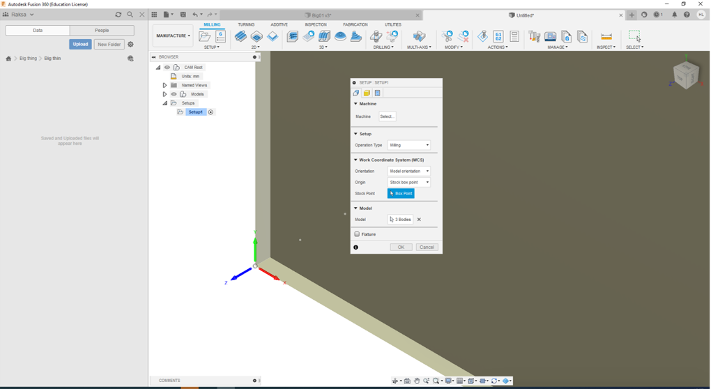
Step 4. I move Stock Point to bottom left corner (x-and y-axes) and top level (z-axe)
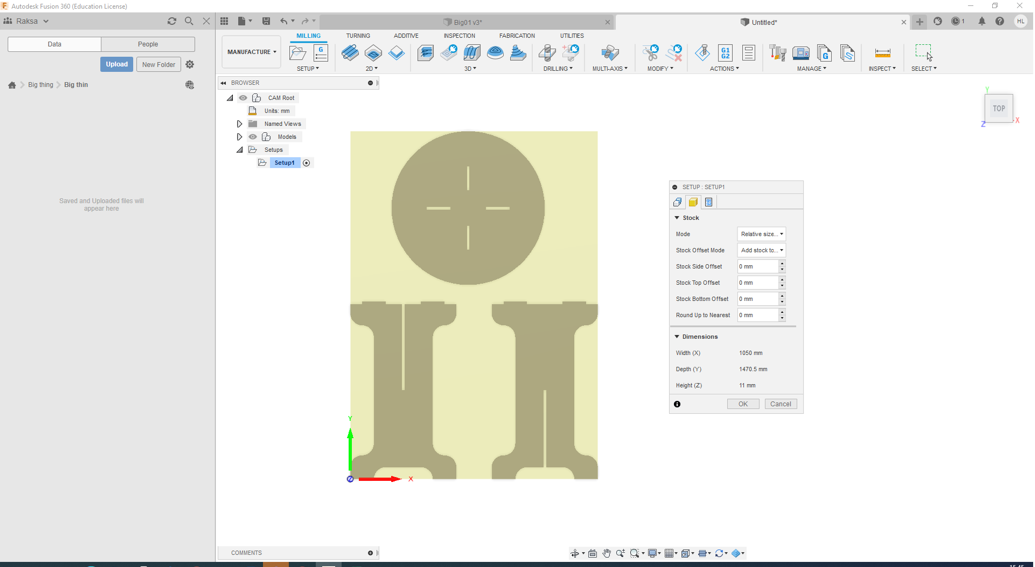
Step 5. Then I defined Stock values, the values are as follows:
- Mode: Relative size
- Stock Offset Mode: Add stock to
- Stock Side Offset: 0 mm
- Stock Top Offset: 0 mm
- Stock Bottom Offset: 0 mm
- Stock Up to Nearest: 0 mm
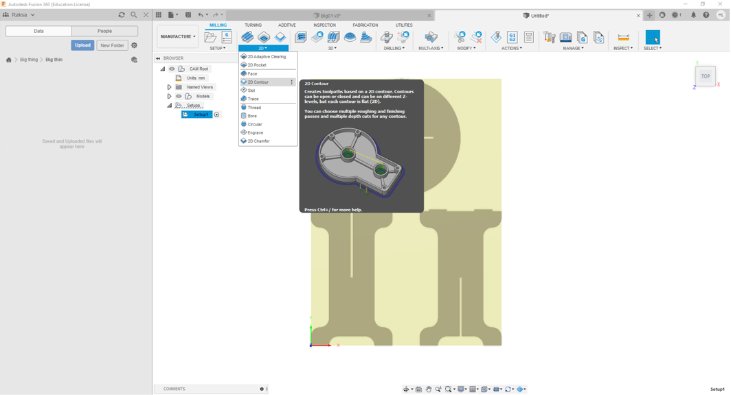
Step 6. Then I created toolpaths by using 2D Contour command
Step 7. Then I defined 2D Contour values.
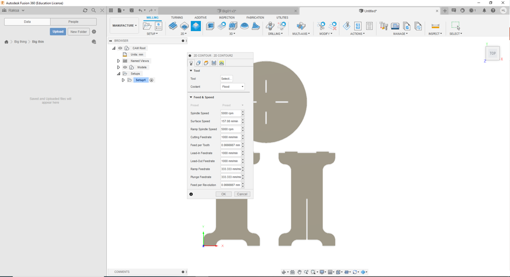
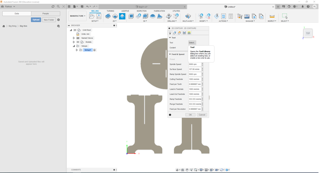
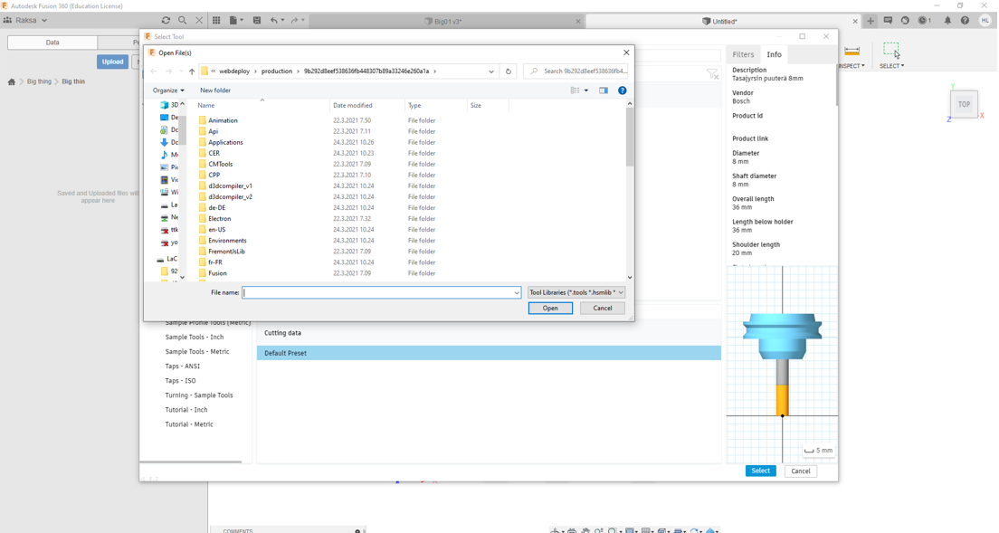
Step 8. First I defined Tool Library by select Tool Library.
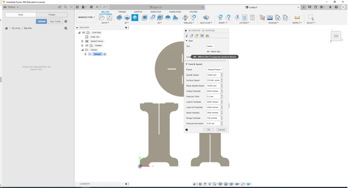
Step 9. First time I have to import right tool library. In Fab Lab Oulu we use FABLAB ROUTERI TOOLS 2020-3.hsml . I chose the 8mm flat end mill.
Step 10. Then I defined Feed & Speed values, the values are as follows:
- Spindle Speed: 15 000 rpm
- Surface Speed: 376.991 m/min
- Ramp Spindle Speed: 15 000 rpm
- Cutting Feedrate: 6 000 mm/min
- Feed per Tooth: 0.2 mm
- Lead-In Feedrate: 4 000 mm/min
- Lead-Out Feedrate: 4 000 mm/min
- Ramp Feedrate: 3 000 mm/min
- Plunge Feedrate: 750 mm/min
- Feed per Revolution: 0.05 mm
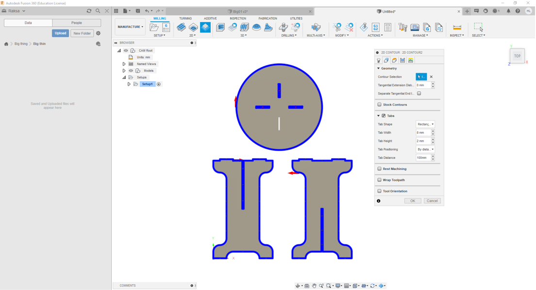
Step 11. Then I selected objects which have to mill by using Contour Selection command. To avoid parts loosening during milling process I designed Tabs, the values are as follows:
- Tab Shape: Rectangular
- Tab Width: 8 mm
- Tab Height: 2 mm
- Tab Positioning: By distance
- Tab Distance: 100
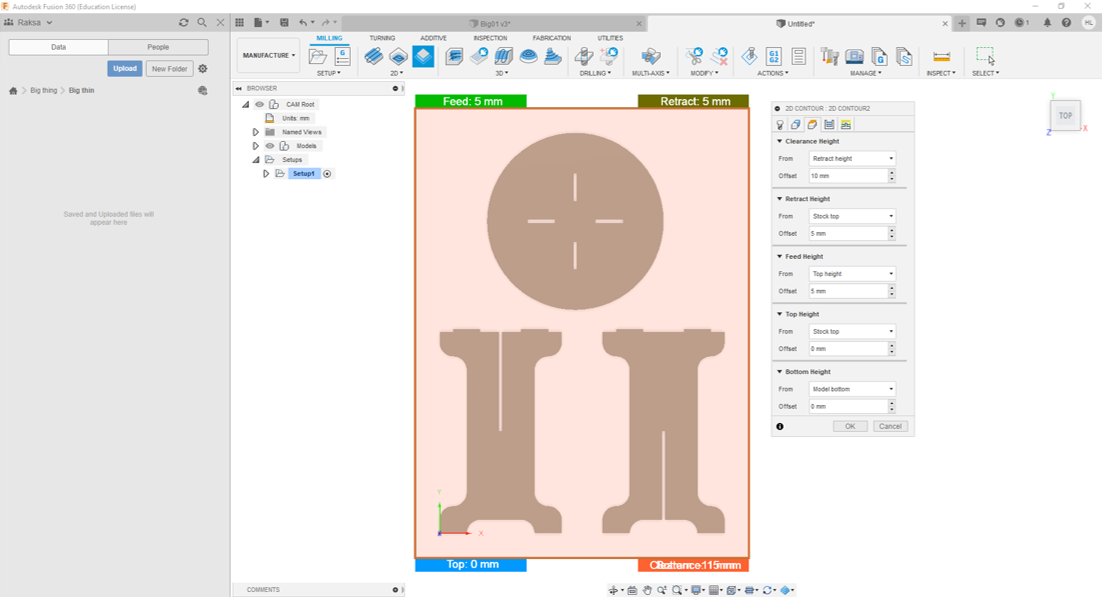
Step 12. Next I used mostly default settings. I changed only the Bottom Height to Model bottom
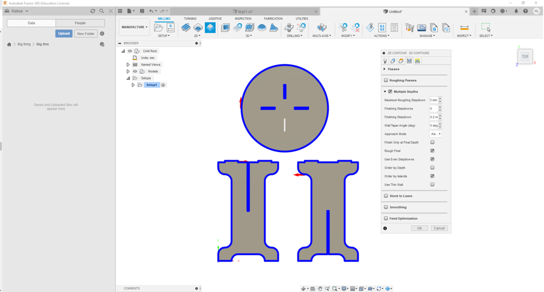
Step 13. Then I set Maximum Roughing Stepdown to 3mm. To avoid extra pressure to end mill I set Use Even Stepdowns. The rest of values are defaults.
Step 14. I checked toolpaths by runnig simulation
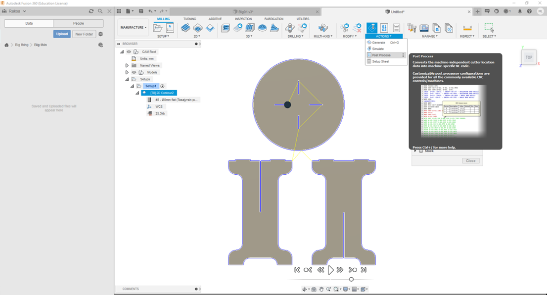
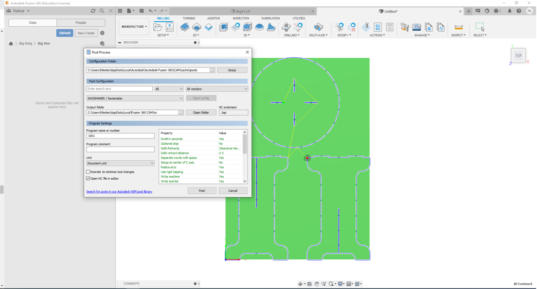
- Finally I created cnc file by Post Process command. First I had to insert FabLabCNC.cps to the Configuration Folder. At last I clicked Post button to create cnc file.
Parts fabrication - Milling
The supevisor of milling was Fab Academy Alumi 2017 Eino Antikainen. He advised me during milling.

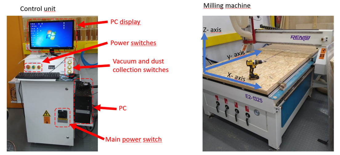
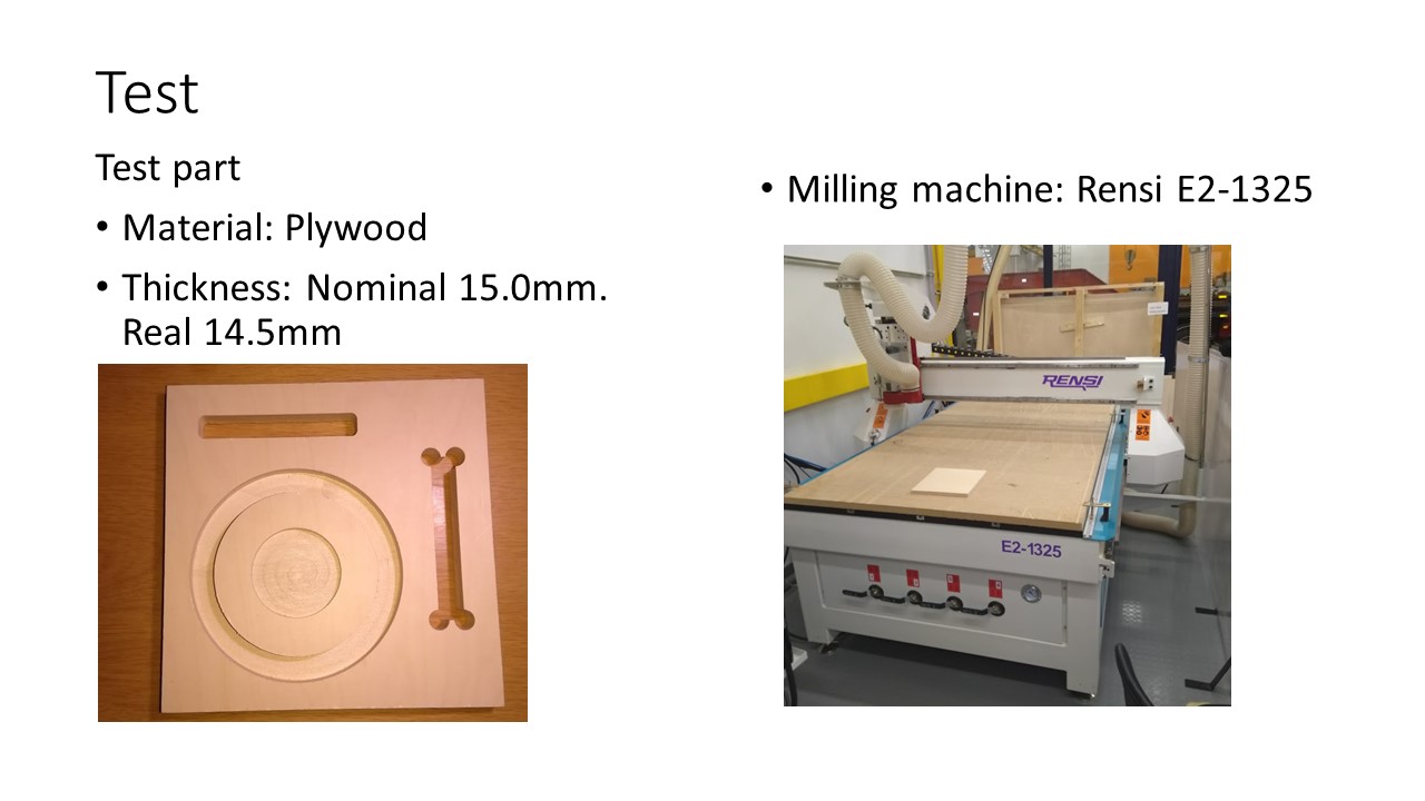
In FabLab Oulu milling machine is Rensi E2-1325. Control software is NcStudio in PC.
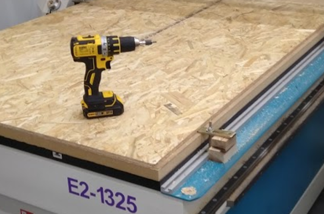
I fastened OSB with screws by using hand-held machine.
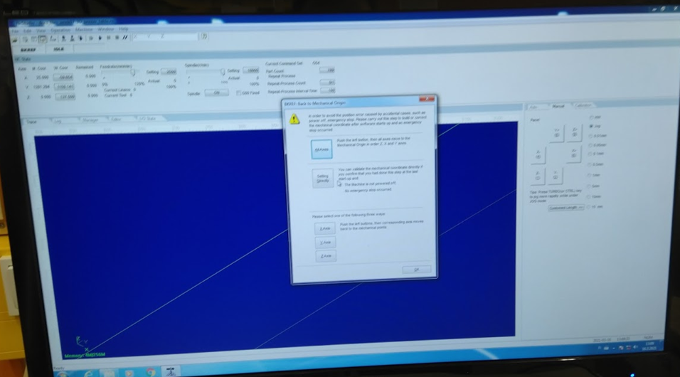
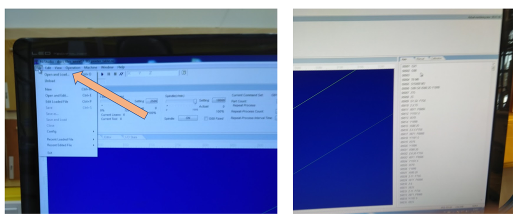
First I opened NC studio. Then I selected All axes button from Back to mechanical origin Pop Up windows. Then milling runs spindle to mechanical origin.
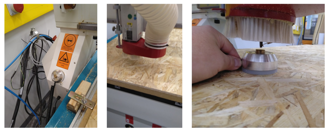
Then we checked that tool bit was right. We remove dust cover (red part). It is very import to note that collet have to right to bit.
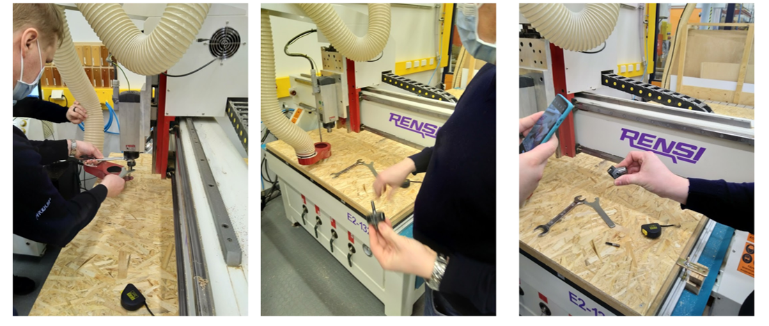
Then I moved spindle to edge of OSB by using Direction Buttons x-,x+ y- and y+ buttons. When position of spindle was right I set the workpiece coordinates x- and y- positions.
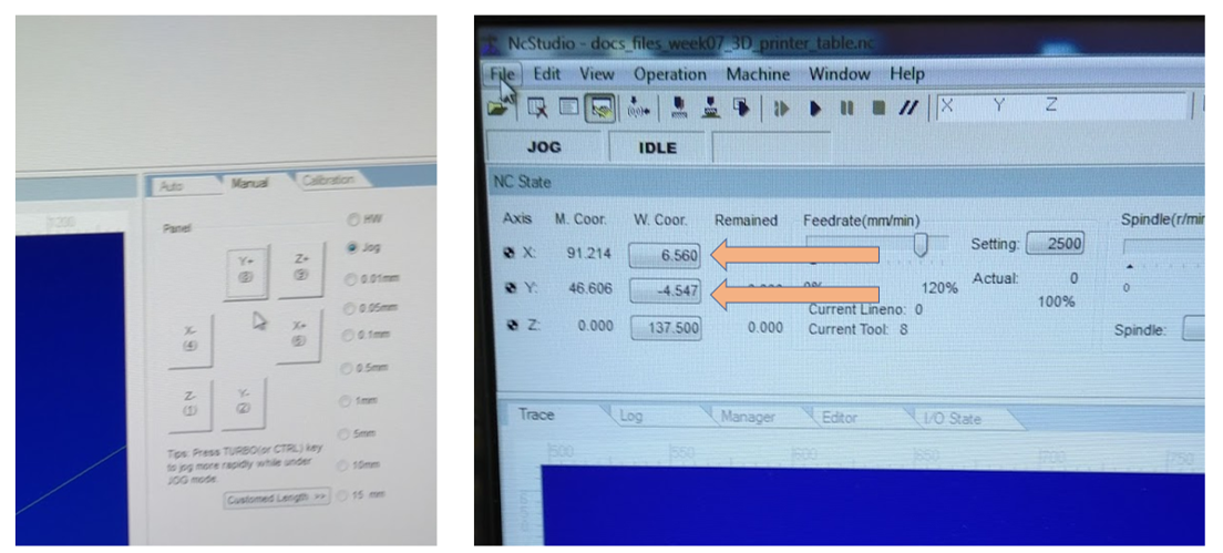
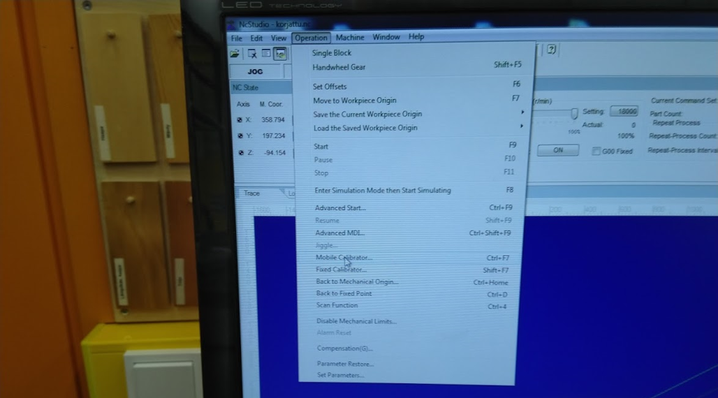
Then I moved spindle to near middle of board by using x-,x+ y- and y+ buttons. I set z-axis by Mobile Calibrator… . I took the calibrator tool and set under bit. Then I start calibration by clicking Continue button. Calibration started and bit touched lightly the calibrator tool. After that Calibration was also done in direction z.
Then I opened my cnc file which I greated by using Fusion 360. G-code was shown in right side on windows.
Before milling I started simulation to check that everything was OK.

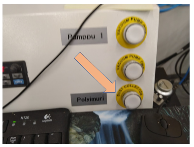
Then I was ready to start milling. First I tuned dust collector on by pushing Dust Collector button. Then I
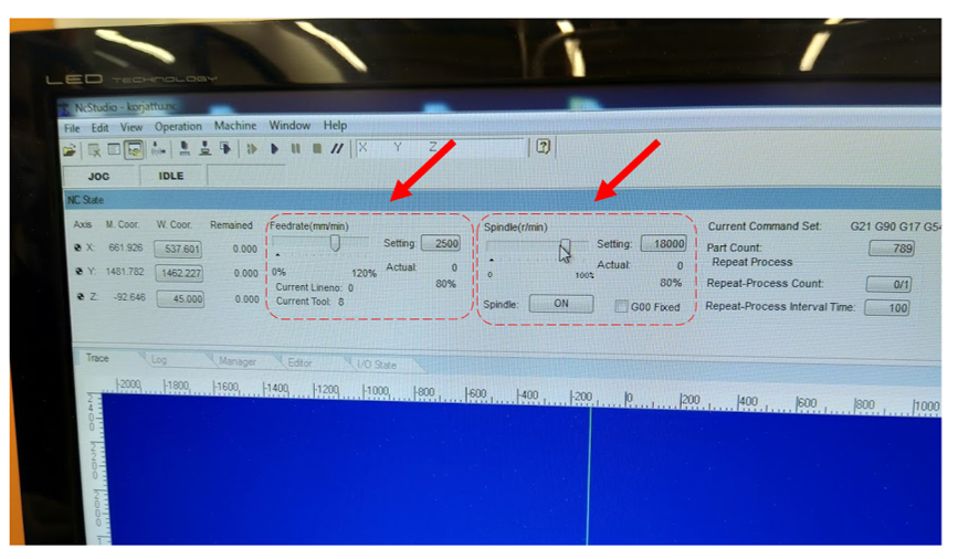
To start milling I Selected menu item [Operation (O) |Start(S)]. During milling process I adjusted Feedrate and Spindle speeds.
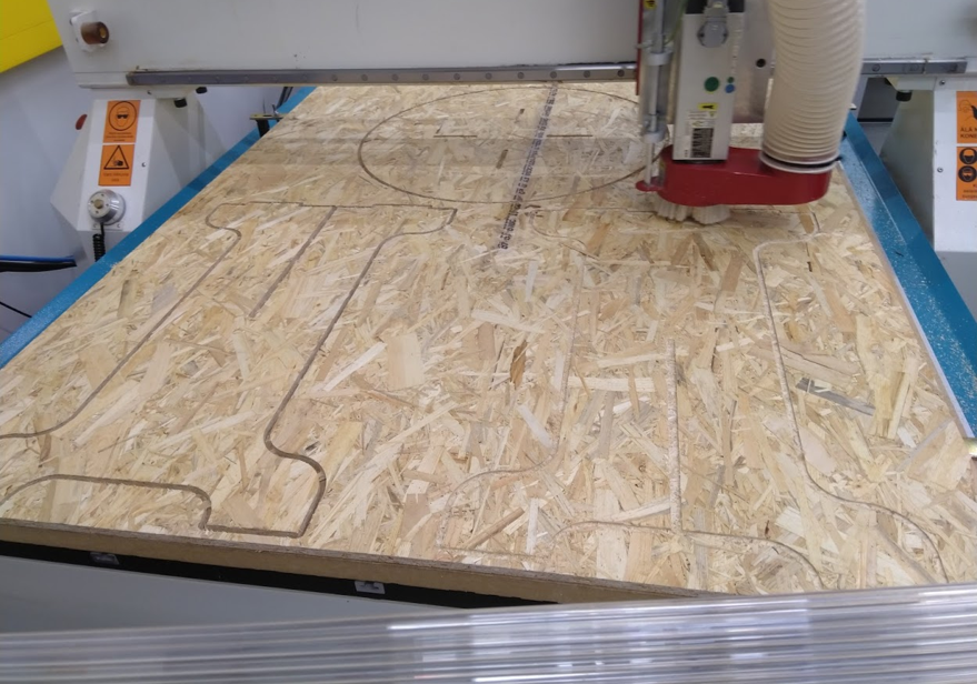
After milling I remove parts from board by using knife.
Assembling
I fitted parts together by using Rubber mallet. At last my big thing was ready.
Files
CAD model:
NC Code:
Conclusion
I learned lot of fabrication process. First have to design object and it’s parts. Then make toolpaths to remove parts from raw material.
I make one mistake to add tabs also to joint holes on top.
I found NCStuodio Users’ Manual
http://www.ltcnc.cn/static/upload/file/20180511/1525999428207575.pdf
Group assignment
Our group tested accuracy of milling machine by measuring dimensions of test part and compare to designed dimensions.
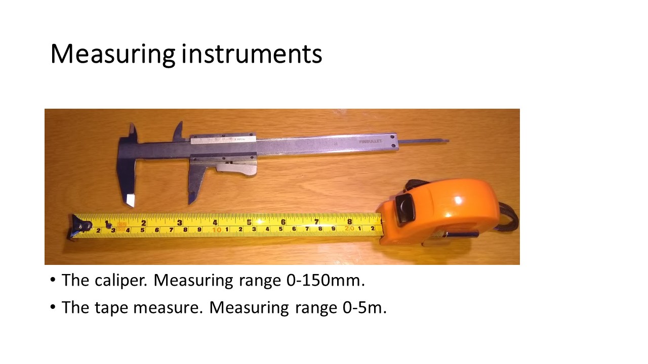
Measuring
We used a Caliper and a Tape measure to measure dimensions of test part. These measure instruments were not calibrated.
We measured 22 different distances of test part
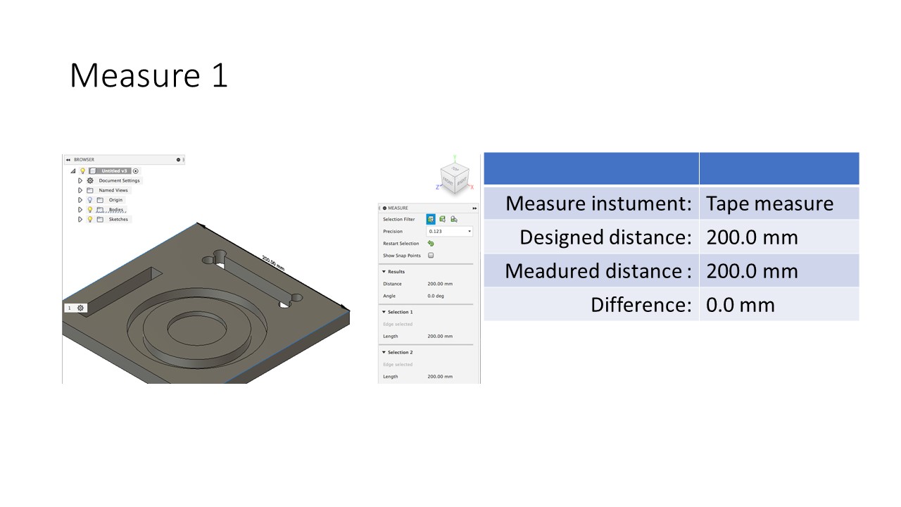
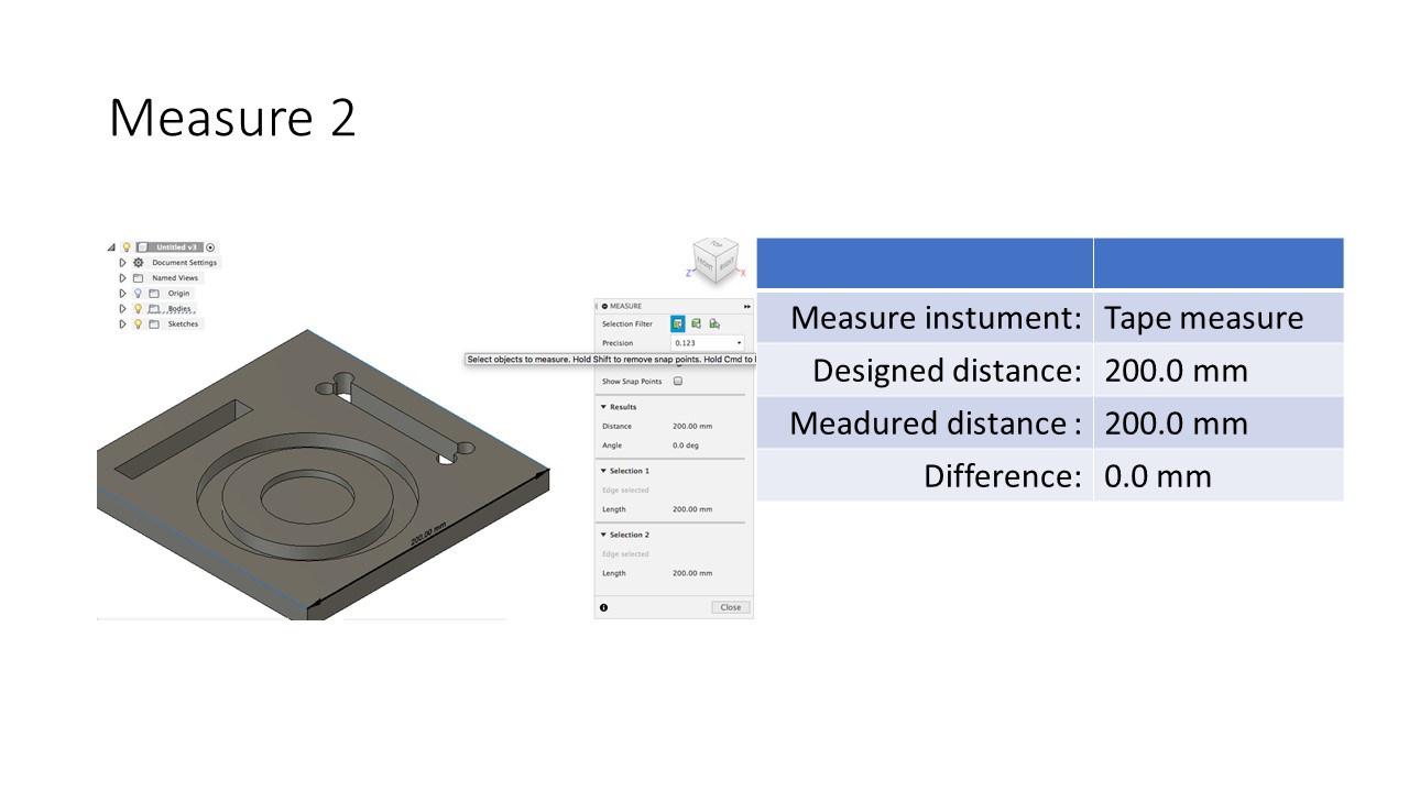
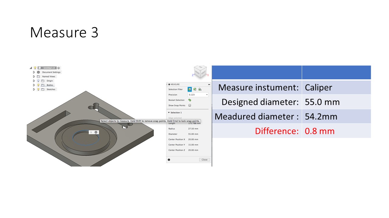
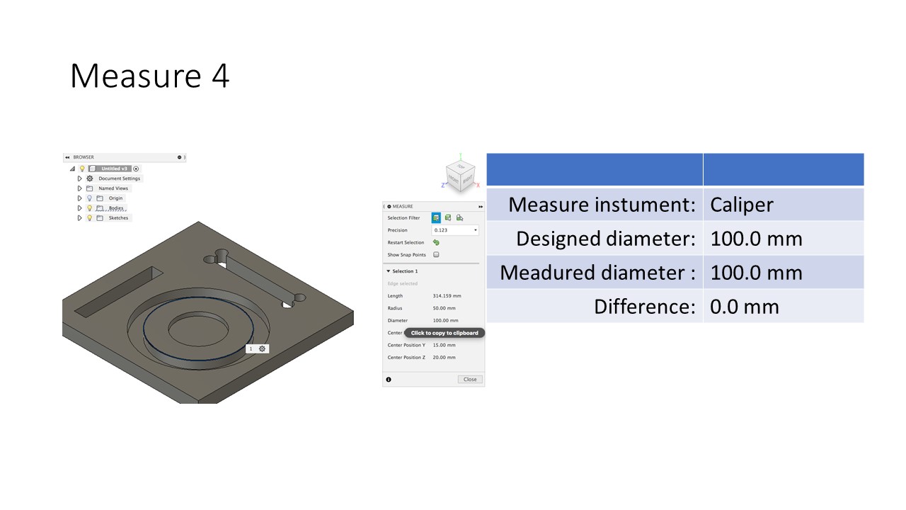
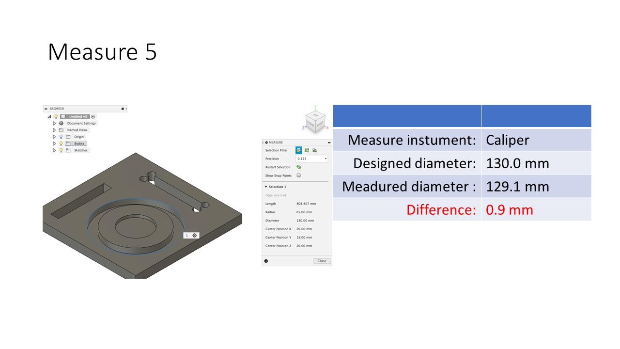
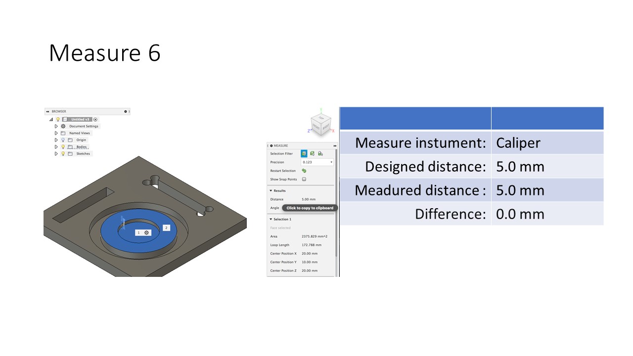
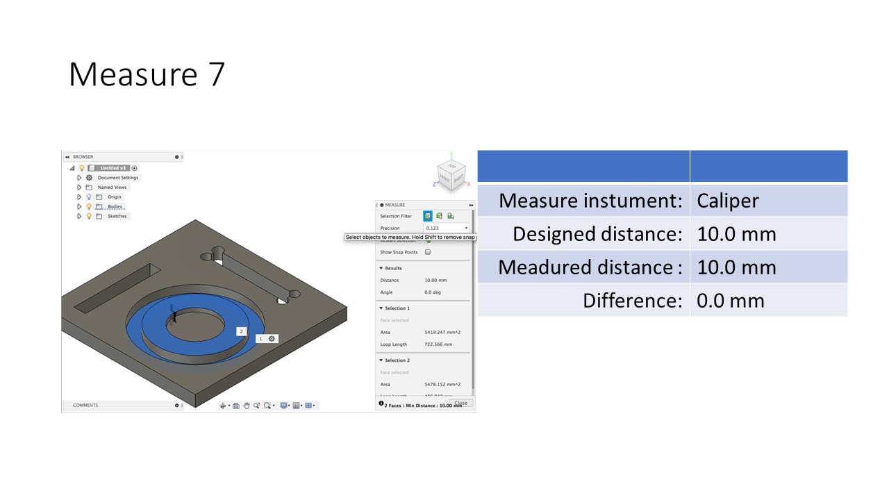
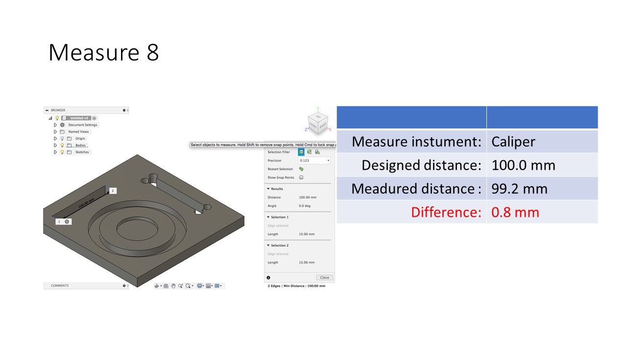
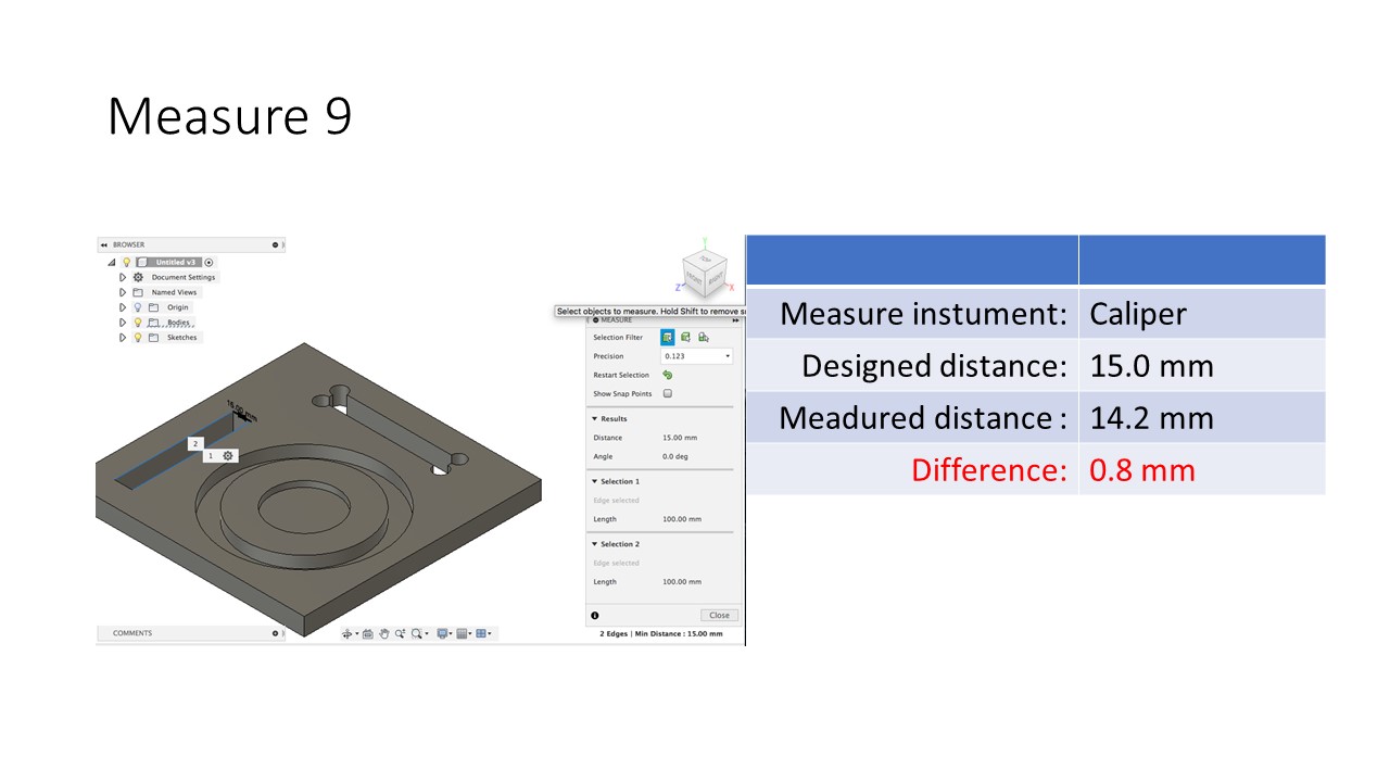

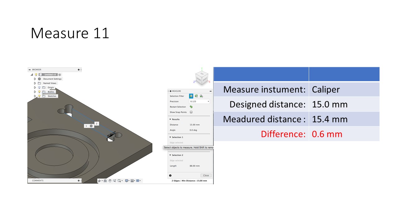
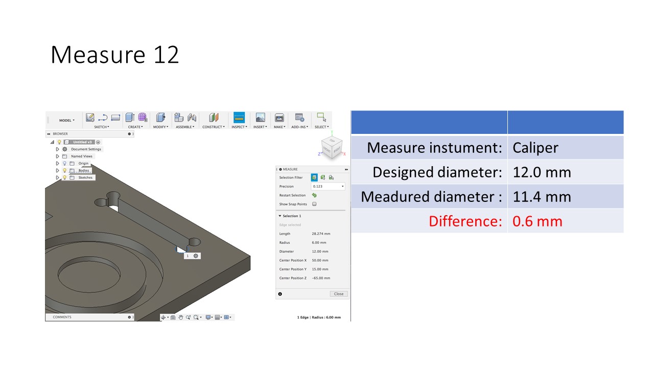
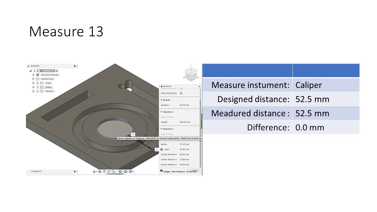
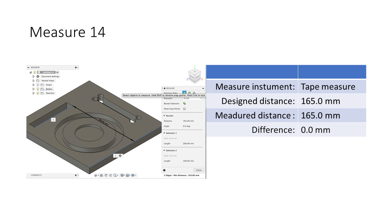
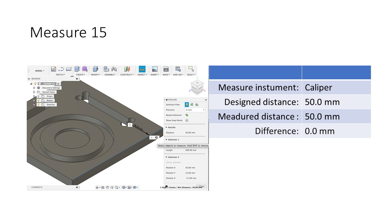
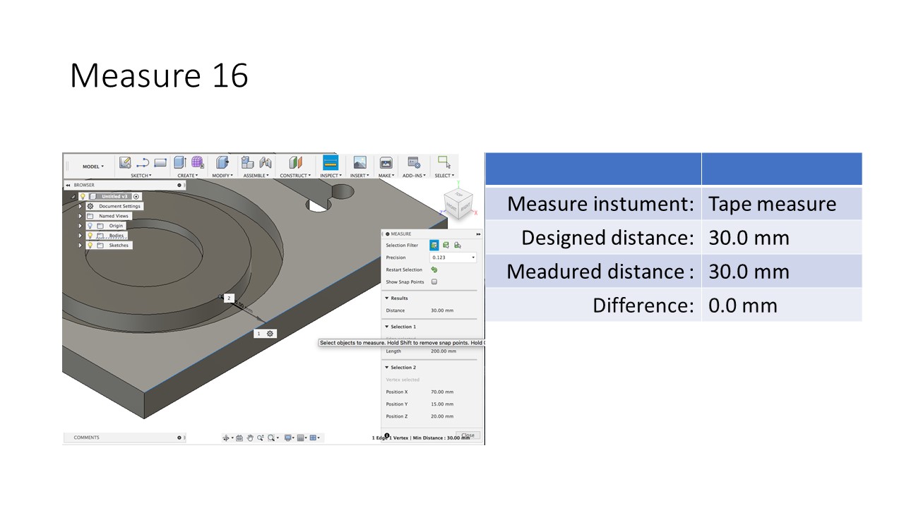
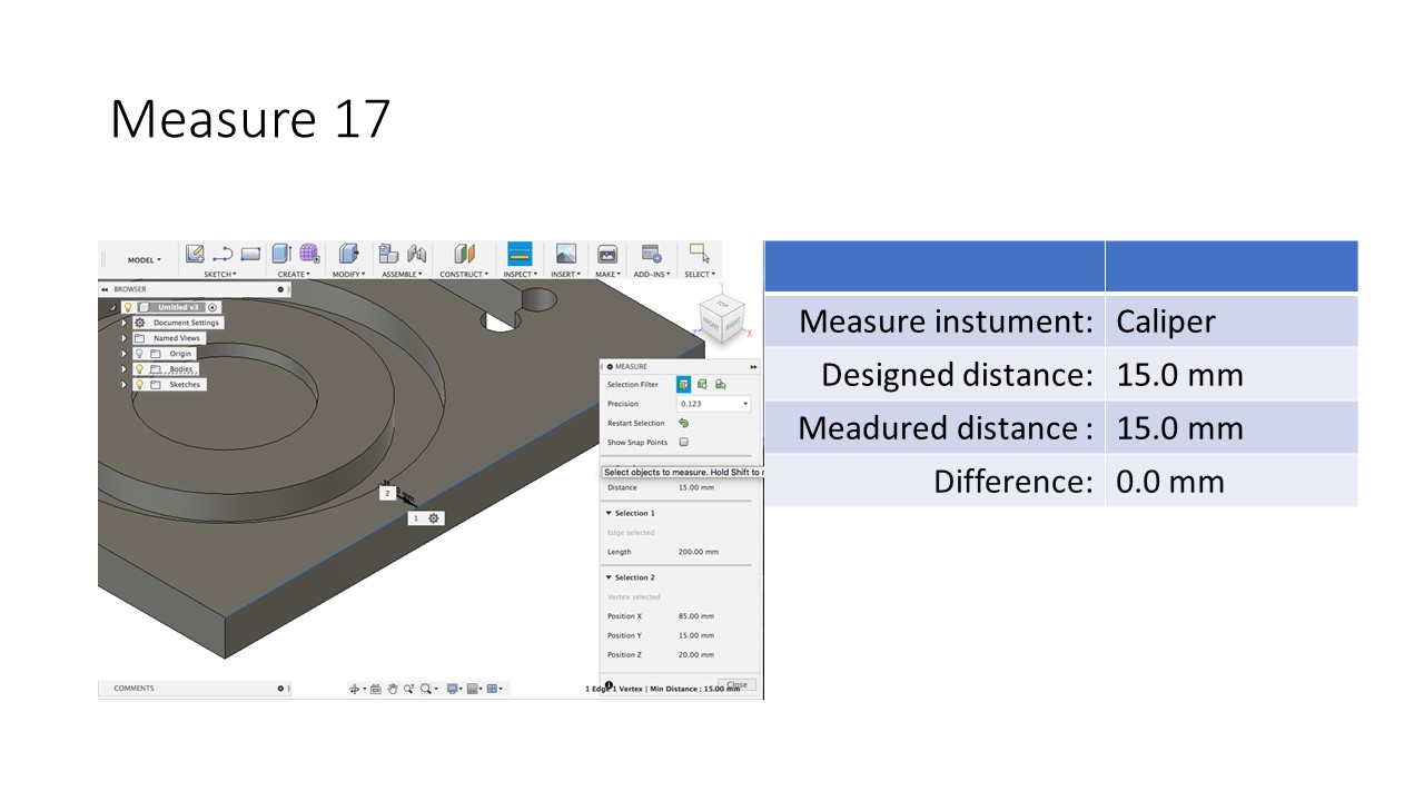

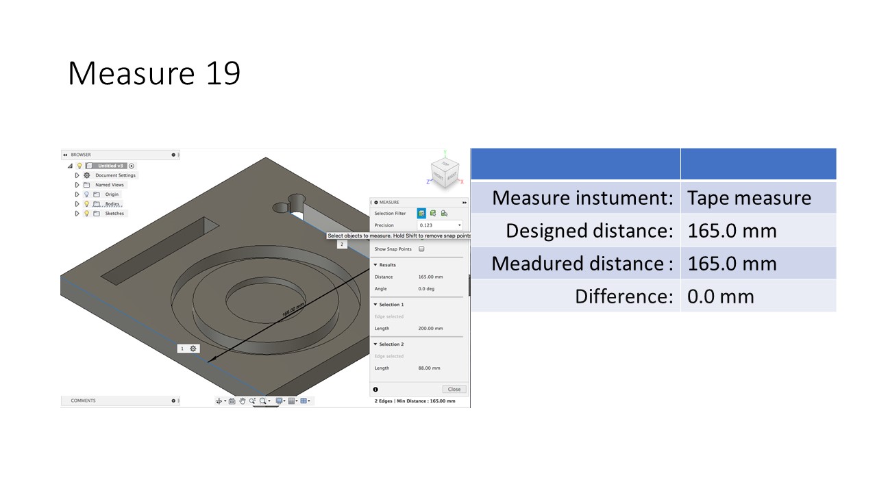

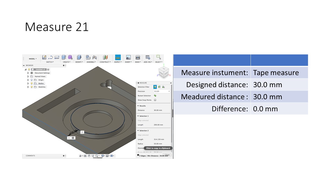
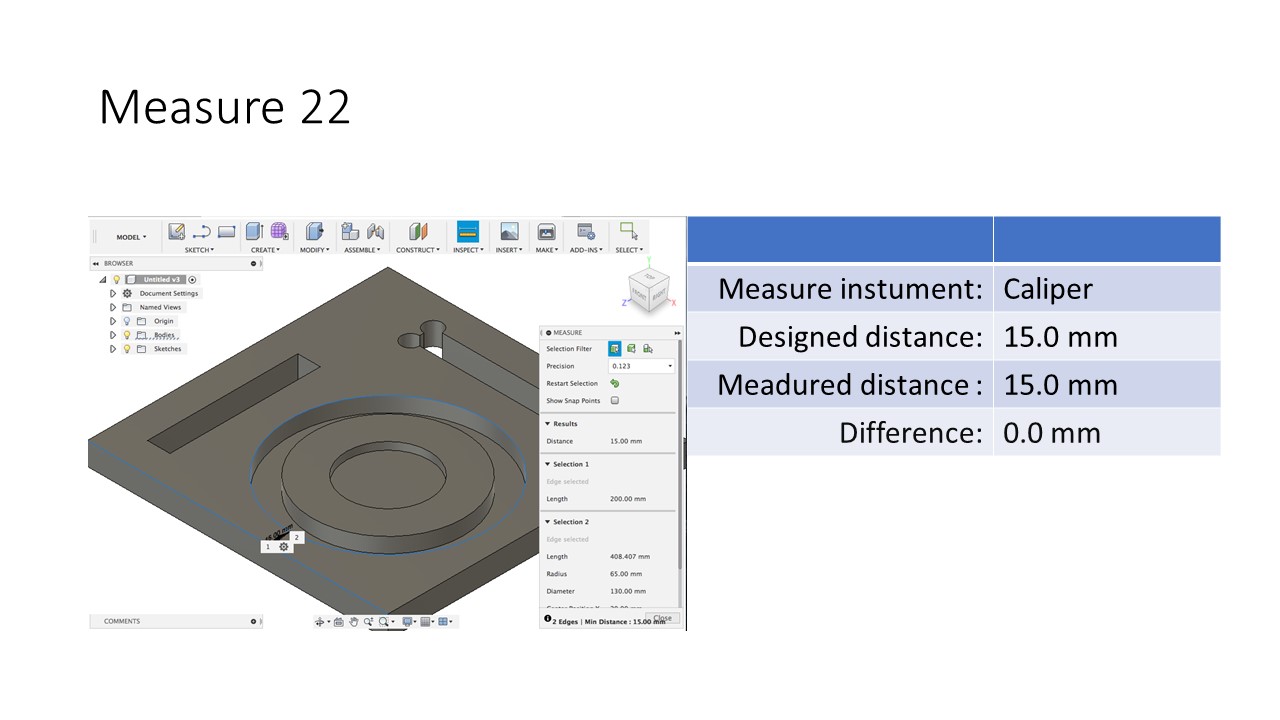
Measured dimensions 3, 5, 8, 9, 10, 11 and 12 are different from designed dimensions but rest of measured dimensions are excat with designed dimensions.
Conclusion of group assignment
Assumedly problem is inaccuracy of Inside small jaws (Caliper) not milling process. Hence milling process was accurate.