3. Computer Aided design
Assignment
model (raster, vector, 2D, 3D, render, animate, simulate, …) a possible final project, compress your images and videos, and post it on your class page
Idea
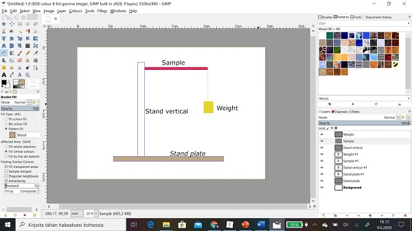
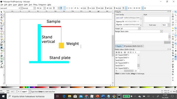
First of all, I run the rule over tool software which are listed on the Fab Academy Web site. Then I decided to focus potential programs to model parts of my final project such as stand, sample material (red), weight.

GIMP
GIMP (Gnu Image Manipulation Program) is raster graphics editor software and is available for Linux, macOS, and Microsoft Windows. GIMP is free and open-source software (FOSS). You can download it Official website of the GNU Image Manipulation Program (GIMP)
Import formats:
Export formats:
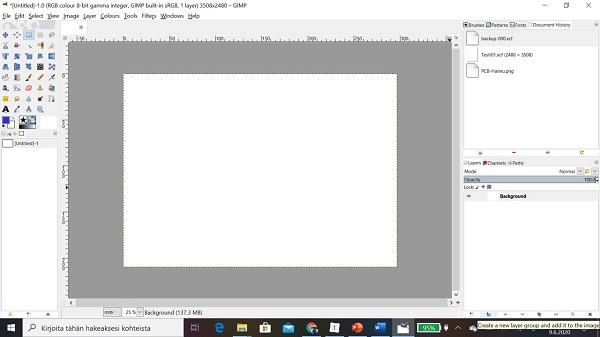
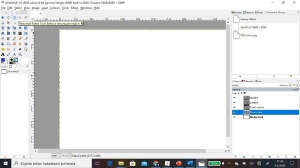
Step 1: I opened GIMP
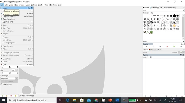
Step 2: First I created a new image by licking File .. > New.. >
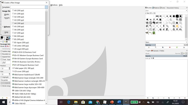
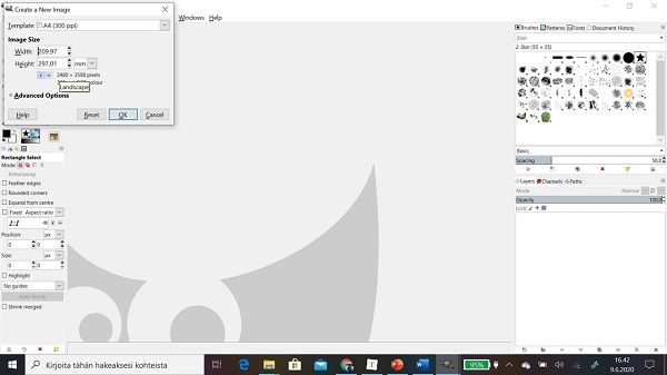
Step 3: I chose to template A4 landscape
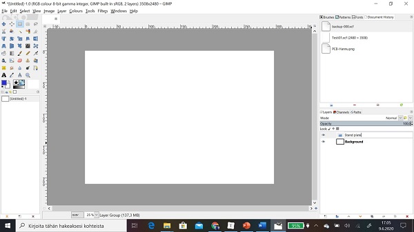
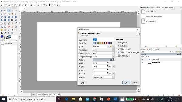
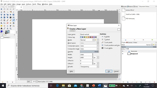
Step 4: Then I created layers for every objects by choosing from ribbon Layer > New Layer
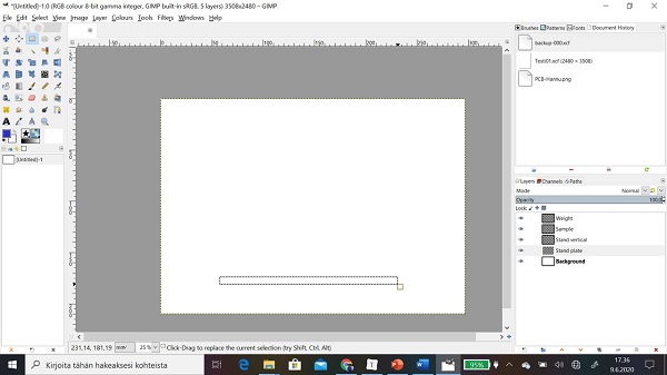
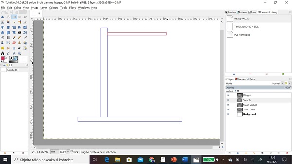
Step 4: Then I started to draw objects to right layer by using Rectangle select tool.
Step 5: I clicked first corner (at the same time holding left mouse button down), dragging to opposite corner and released left mouse button.
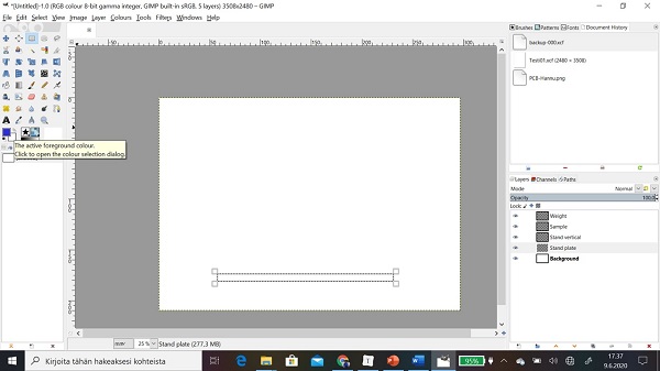
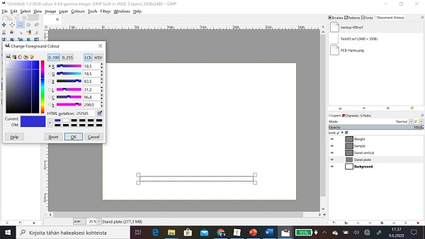
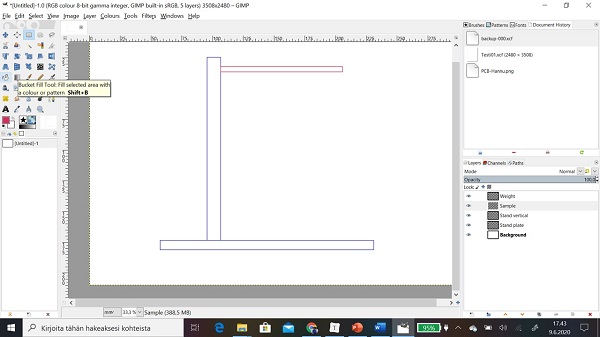
Step 5: Then I chose colour to object from tool by clicking The active foreground colour.
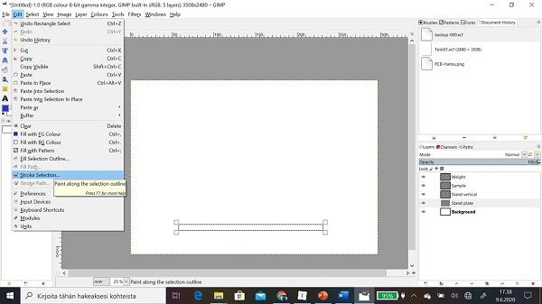
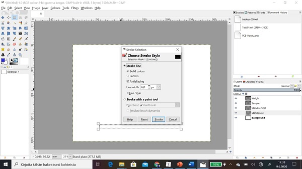
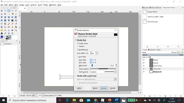
Step 6: Then I chose Stroke selection… to approve object.

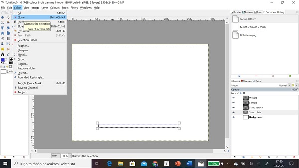
Step 7: Then I released selection of object by clicking Select > None
Step 8: Now I got my first object.

Step 9: I drew same way rest of objects
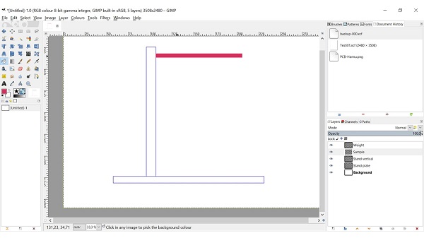
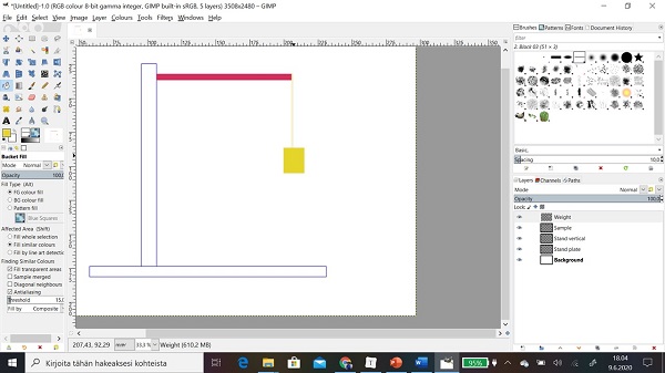
Step 10: I used Bucket Fill tool to filling sample object
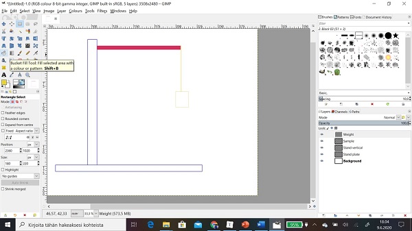
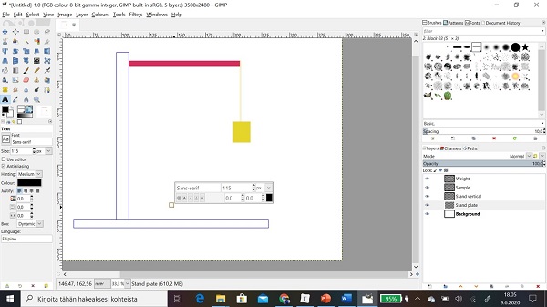
Step 11: Then I named object by using Text Tool

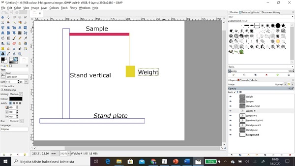
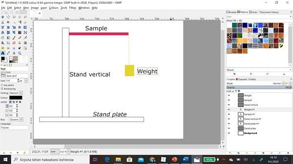
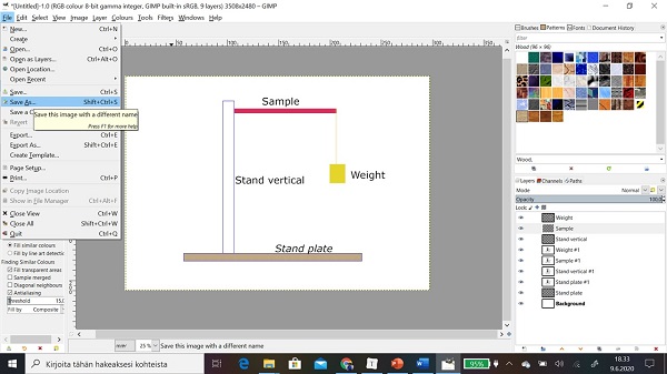
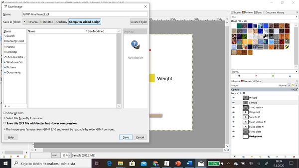
Step 12: At the rest I save file GIMP format by using Save As.. >
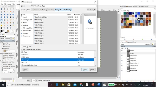
Step 13: I exported file to jpg format by using File > Export As …
Links
https://www.gimp.org/tutorials/list-all.html
https://www.gimp.org/tutorials/Draw_A_Paint_Brush/
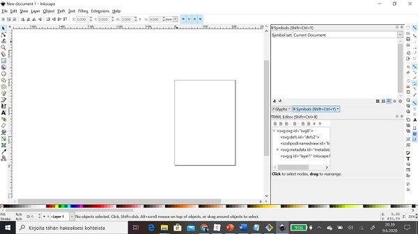
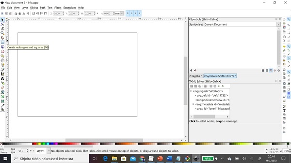
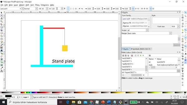
Inkscape
Inkscape is vector graphics editor software and is available for Linux, macOS, and Microsoft Windows, Inkscape is free and open-source software (FOSS). You can download it Official website of the Inkscape.
User Interface
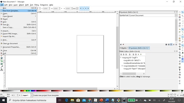
Step 1: First I created sheet by clicking File > Name from Template…
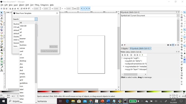
Step 2: I selected a4 and horizontal orientation.
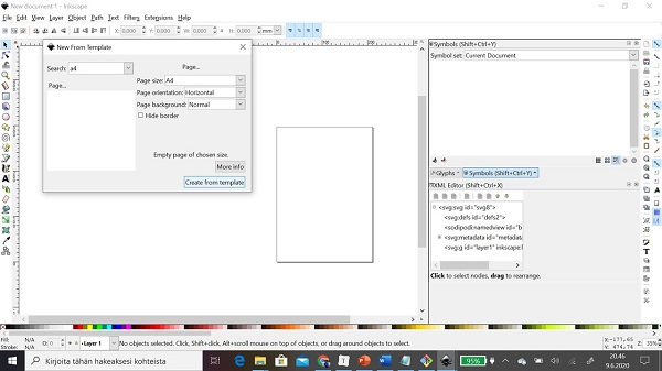
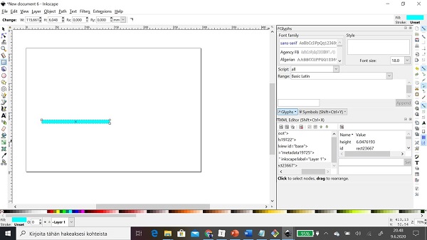
Step 3: Then I got A4 horizontal template sheet. After that I start to drew objects. First I drew stand plate by using Create rectangles and squires. I just clicked rectangles opposite corners and that’s was.
Step 4: I chose colour to object by clicking bottom colour ribbon.
Step 5: I made rest of objects same way.
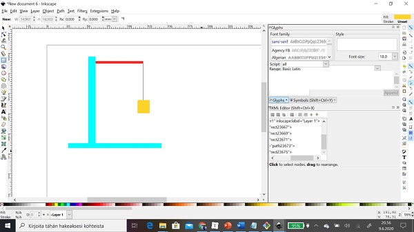
Step 6: Then I named object by Create and edit text objects.
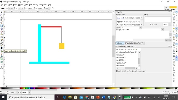
Step 7: I picked right position to text and I wrote text.
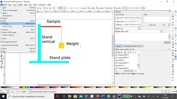
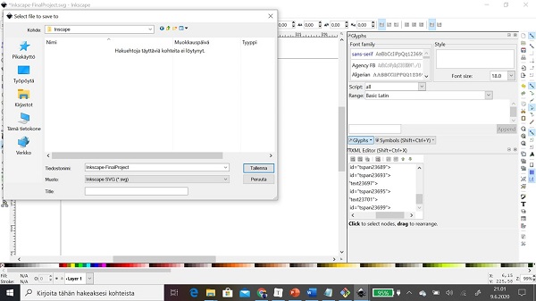
Step 8: At the rest I saved file to .SVG format
FreeCAD
FreeCAD is parametric 3D computer-aided design (CAD) modeler and a building information modeling (BIM) software with finite element method (FEM) support and is available for Linux, macOS, and Microsoft Windows. FreeCAD is free and open-source software (under the LGPLv2+ license). You can download it Official website of the FreeCAD
User Interface
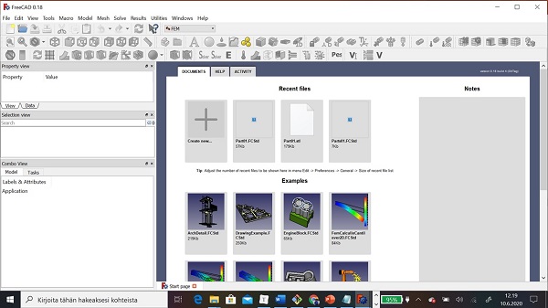
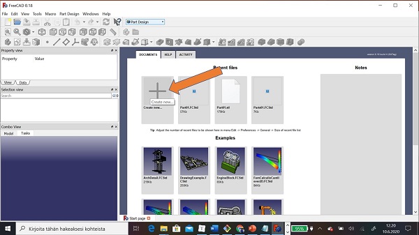
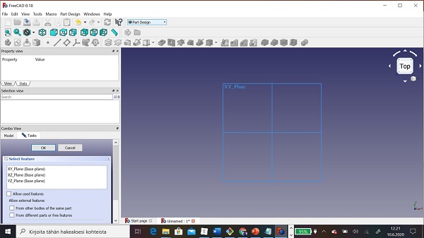
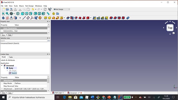
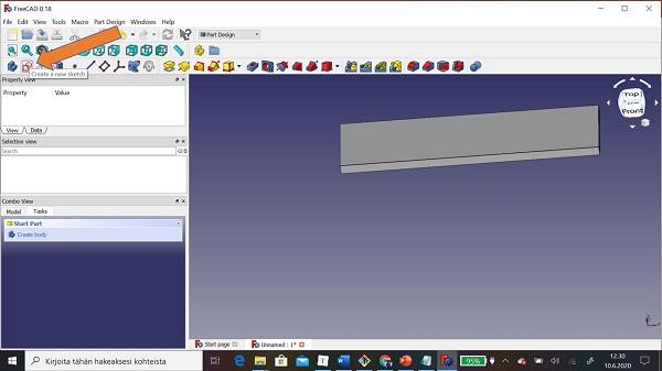
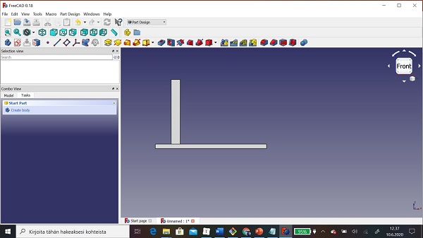
Step 1: First I chose to workbench Part Design. Then I created a new file by clicking Create new…
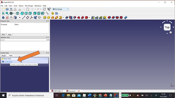
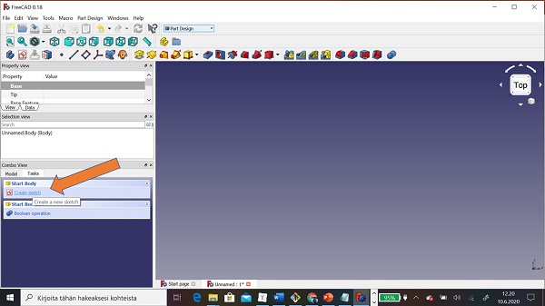
Step 2: I clicked Crete body and then Create Sketch
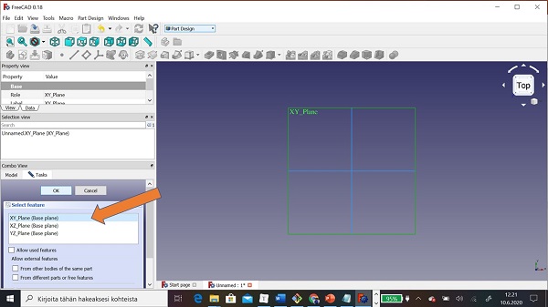
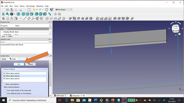
Step 3: I got request to select plane.
Step 4: I selected XY_Plane.
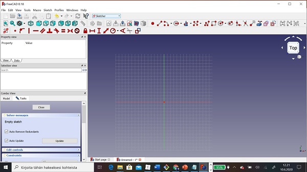
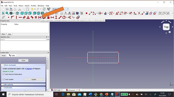
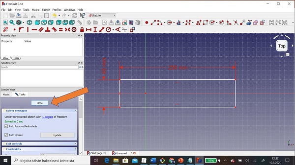
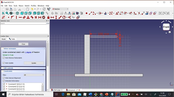
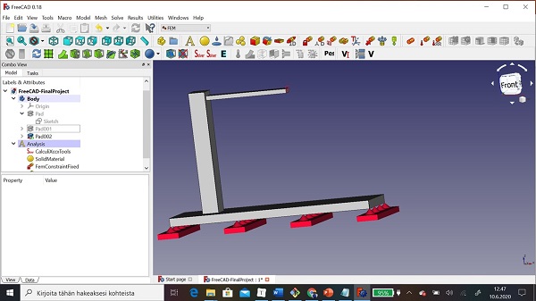
Step 5: Then iI was ready to model objects. First I started to model stand plate by using Create a rectangle in the sketch.
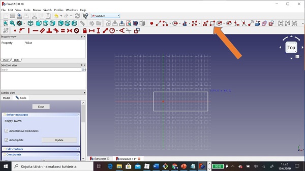
Step 6: I decided that sketch should be symmetric in axle X. I used Create a symmetry constraint between two points with respect to a line a third point. I clicked corner points and axle X.
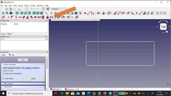
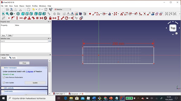
Step 6: Then gave dimensions to sketch by using Fix the horizontal distance between two points or Line ends and Fix the vertical distance between two points or Line ends.
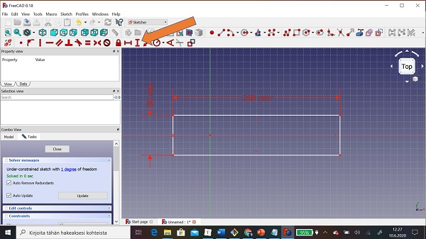
Step 7: Then sketch for stand plate was ready. I clicked Close button to close sketch.
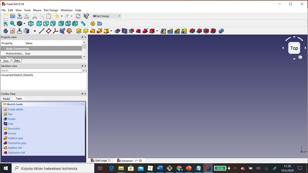
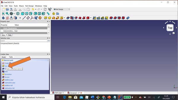
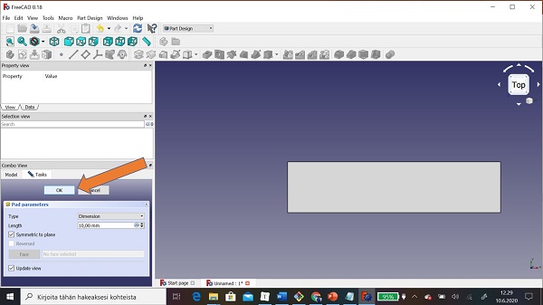
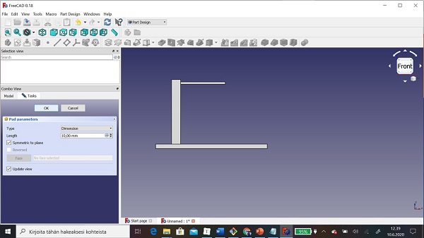
Step 8: Then I gave 3rd dimension thickness by using Pad a selected sketch. The thickness was 15 mm.
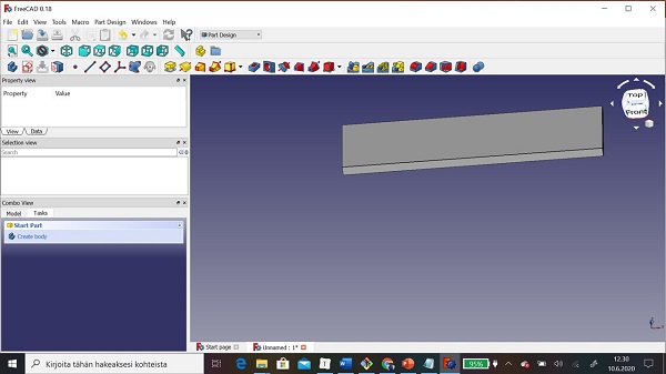
Step 9: Then I modeled vertical stand and sample material same way. I used only XZ_Plane


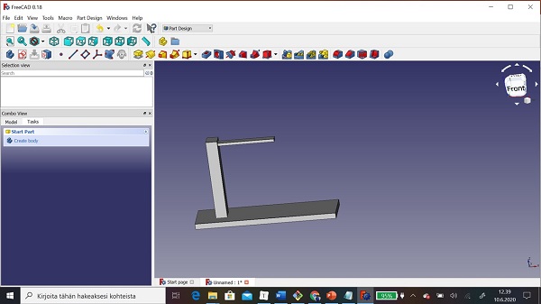
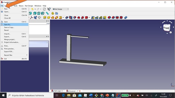
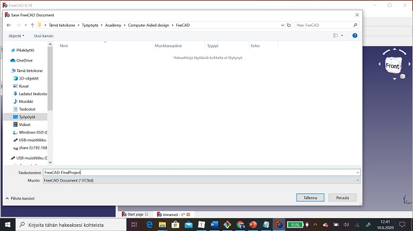
Step 10: Finally I saved file to FreeCAD format .FCstd
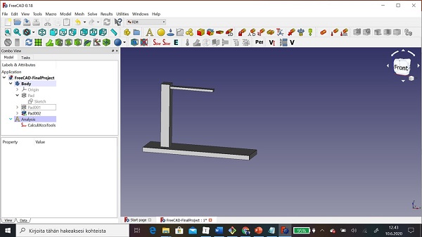
FEM analysis
I make Fem also FEM analysis for my model.
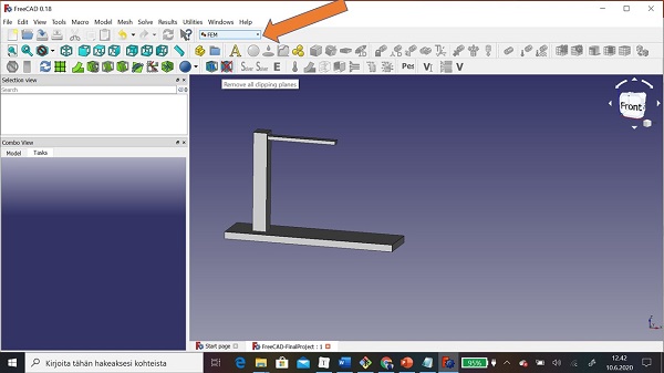
Step 1: First I chose FEM workbench.
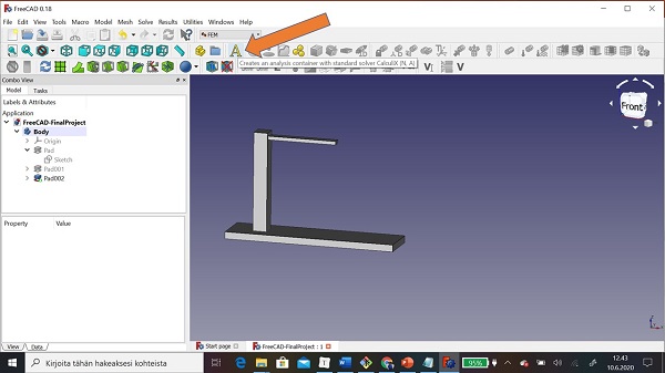
Step 2: Then I added solver by clicking Creates an analysis container with standard solver.
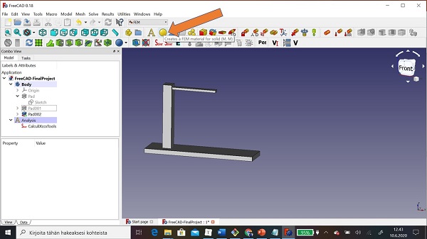
Step 3: Then I added material to model
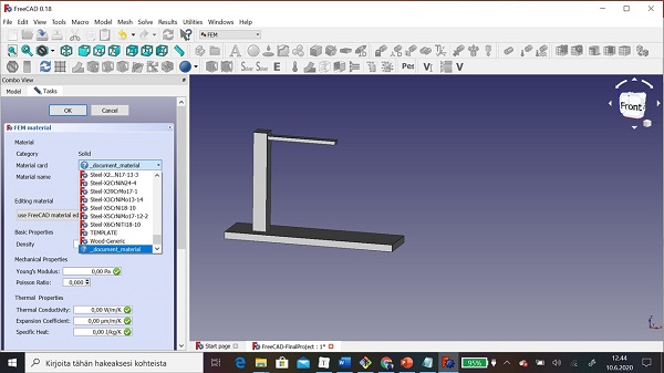
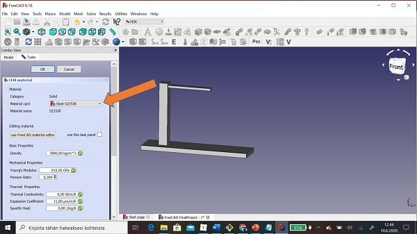
Step 4: I chose Steel S235 JR

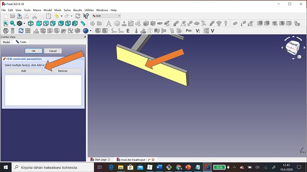
Step 5: I added boundary constraints. First I fixed stand to ground by clicking Create a FEM constraint for a fixed geometric entity.
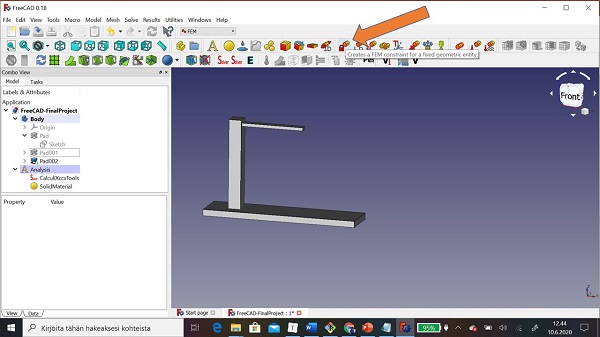
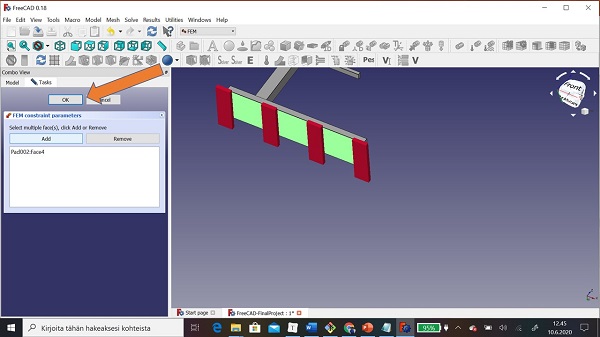
Step 6: I clicked plate, Add button and OK button
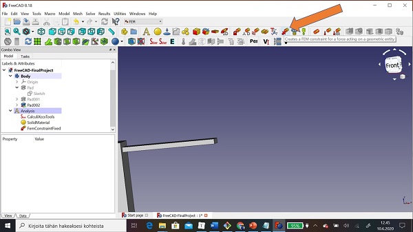
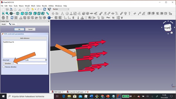
Step 7: Then I gave force to sample material end by clicking Create a FEM constrain for a force acting on a geometric entity.
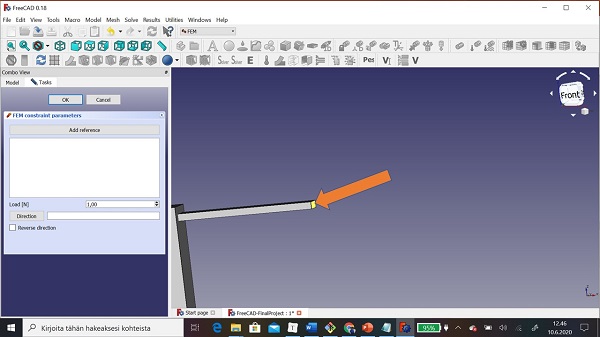
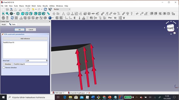
Step 8: Because direction was wrong (axle X), I turned it (axle Z) by clicking Direction button and then edge.
Step 9: Now force was down to up
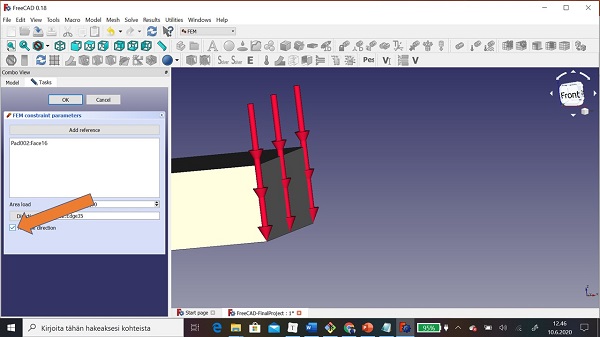
Step 9: Now changed direction by clicking mark to Reverse direction.
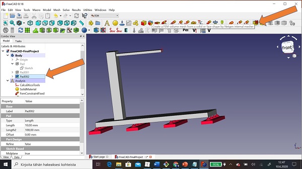
Step 9: Now I created mesh to model by using Create a FEM volume mesh from a solid or face shape by Netgen internal mesher.
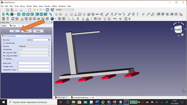
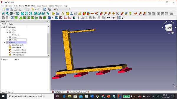
Step 10: Now model was ready to solving.
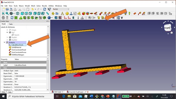
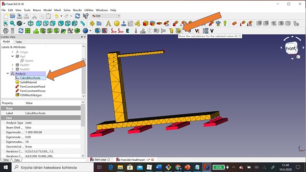
Step 11: I chose Runs the calculation for the selected solver. Note that you mast select CalculiXccxTool first.
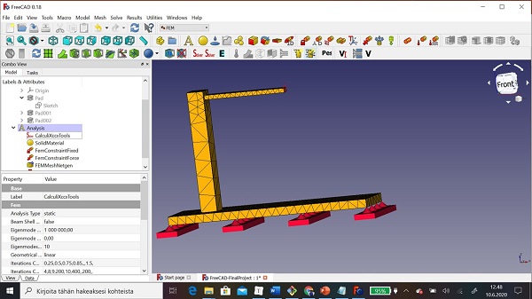
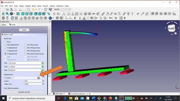
Step 12: When calculation was ready I started to check result
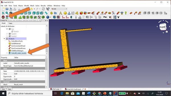
Step 13: I was interested Z-displacement.
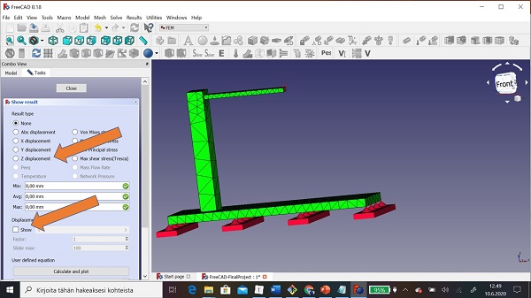
Step 14: I used sliding button.
Video
Files
.FCStd file for FreeCAD FEM analysis
Conclusion
It was very pleased that I have skills to use GIM. Inkscape and FreeCAD. First I model by using AutoCAD which I was familiar with.