Week06. Electronic Design
This week’s assignment, is to create an echo-hello-world board. We need to design the circuit, draw the PCB, mill the board and solder the components, and then upload the hello world program to make it work.
Design the board
We use Eagle to design the board.
Design the schema
The first step is to design the schema. I follow the tutorial and download the fab.lbr file for components I might use. However, after importing, I found nothing new in the library manager. It turned out the fab.lbr file is broken.

Our instructor sent us a 2016 version of fab.lbr and the old version works.
Eagle was quite intuitive. I found all the components, designed the circult schema, then switched to the pcb view, dragged and dropped and use auto-router to make the circuit. The router is complex, and cannot be done in one side.
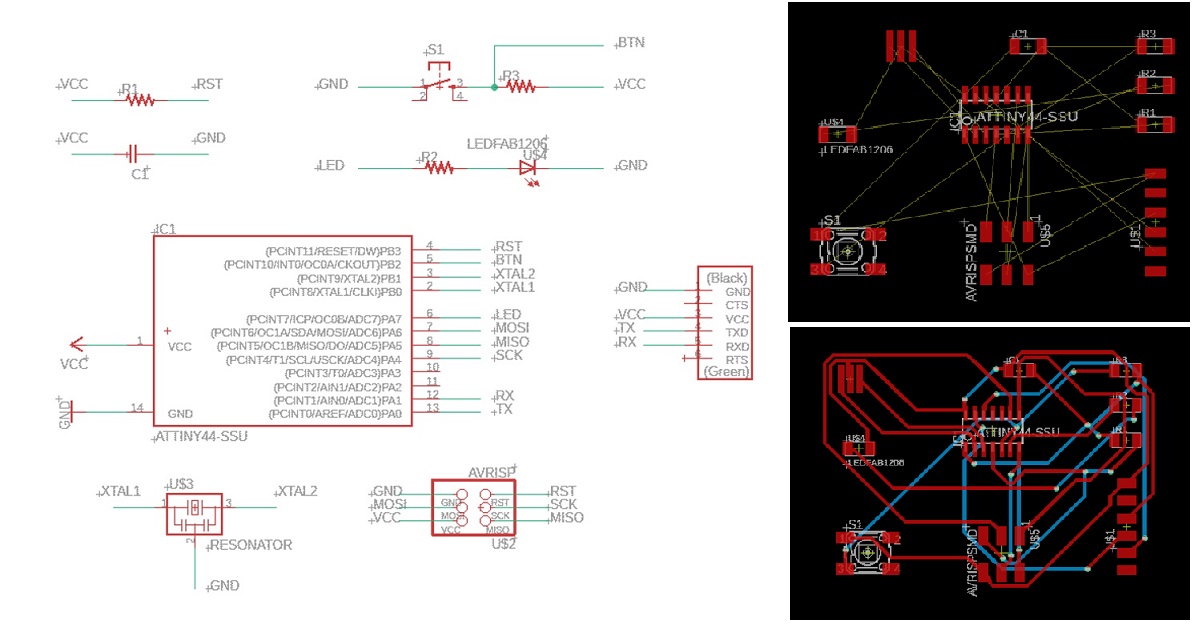
I tried connect components together in schema file, and the result was the same.
I didn’t like to make a two-side board, nor the jumper line. I spent lots of time routing the lines, but still failed.
Then I realized that I need to use some other ports for the button and LED. But which ports should I use? I decided to add components step by step, from those most complex ones to the simple and flexible ones.
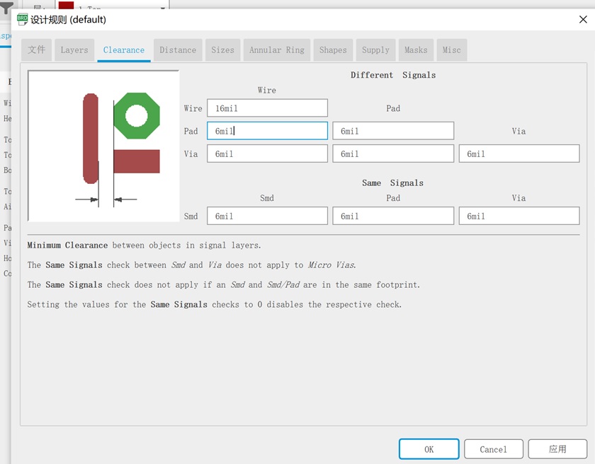
It is important to change the DRC rules of clearance and wire size, to make sure the board can be milled and solderred successfully later.
We choose clearance of 16mil and wire size of 10mil.
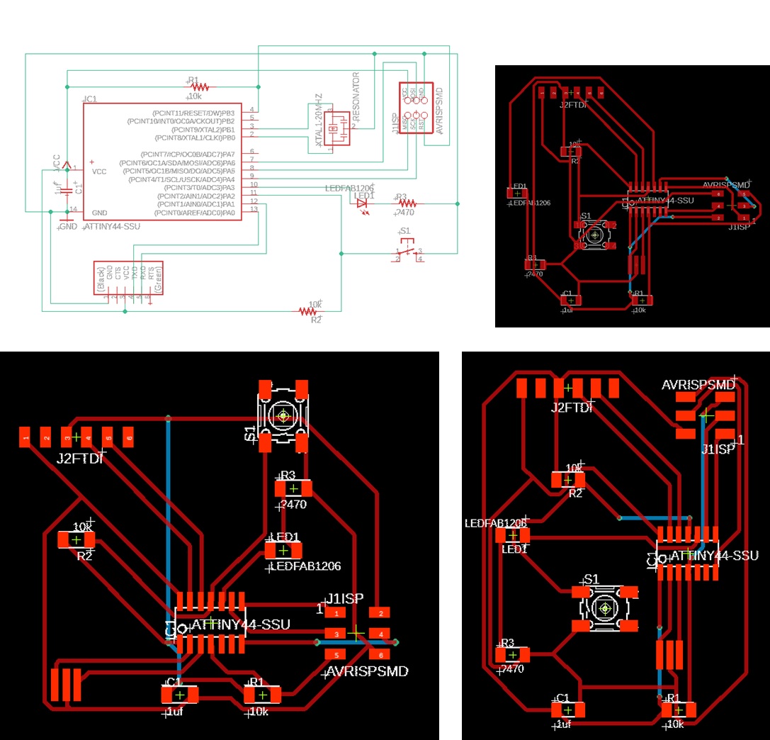
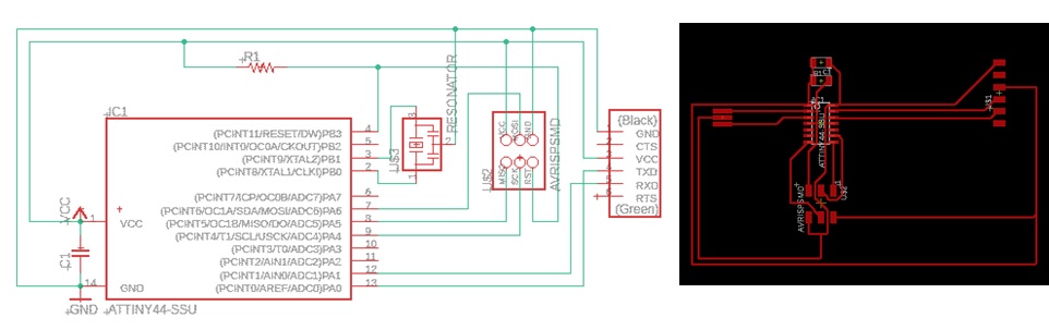
First I added the two 6-header connections.
Then the resistor, capacitor and the resonator. I carefully designed the board, left the left blank place for led (which requies a free pin and GND), and the right blank place for button (which requires a free pin, GND and VCC).
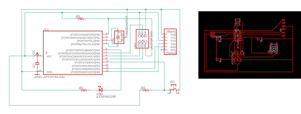
Finally I added the button to pin 10 and LED to pin 6. For ATtiny44, pin7~13 can all be used as analog input, and p5~8 can be used as PWM output. Hence, use pin10 for button and pin6 for LED would be fine.
Although I got this done finally, the router task still seems like a puzzle game to me. I wonder if there is any convenient way to make it work. (The auto-router is even worse.)
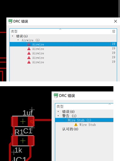
Then I did the DRC check, fixed the airwire and wire stub error.
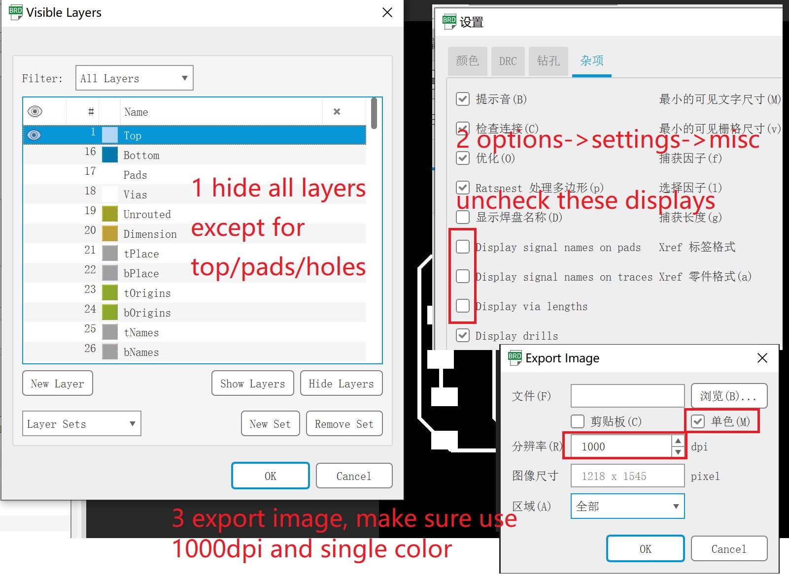
Then hid most layers, uncheck the “display name” checkbox, got an output and modified it to a lovely dog.
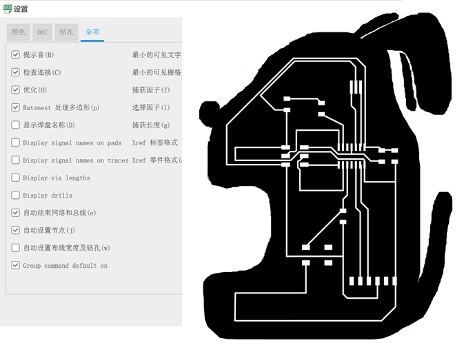
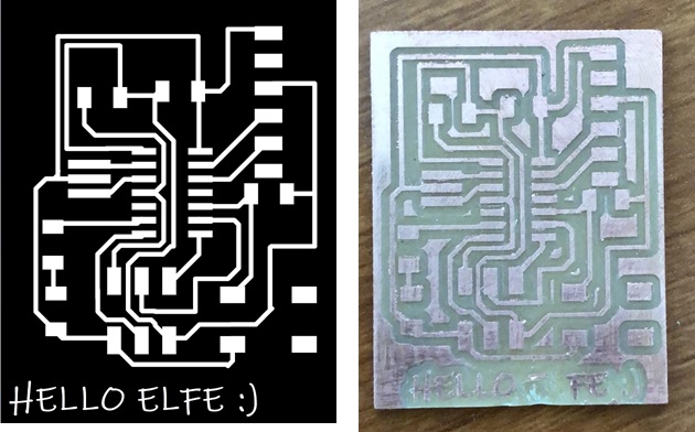
But my instroctor told me it was too big and was a waste of PCB material. So I modified it to a compact version.
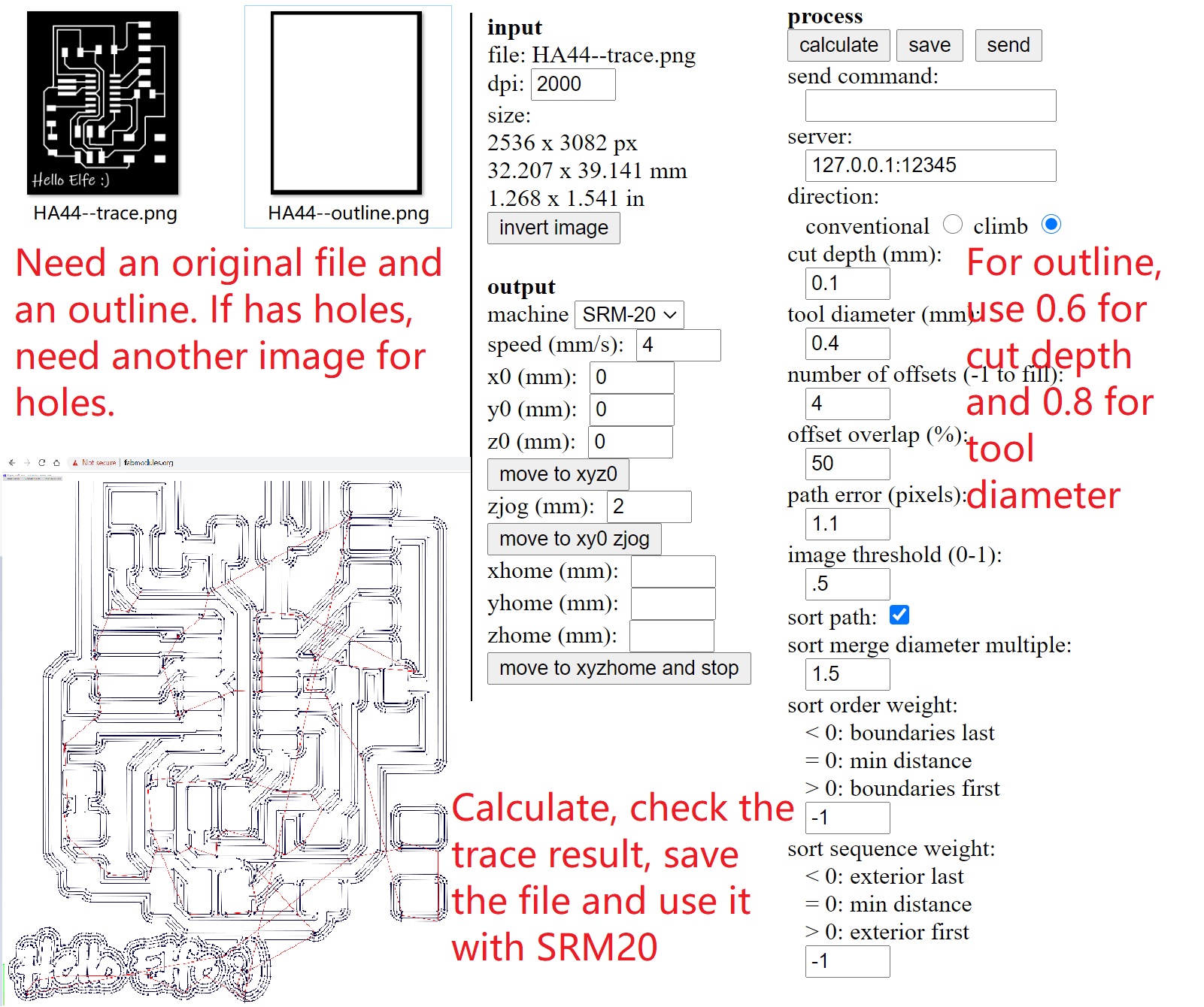
After finishing the design, export it to png file, and use fabmodules to create the trace.
I still could not go to the lab due to corv-virue. Thanks to my instructor and classmates, they helped me to mill the board and sent to me by SFExpress.
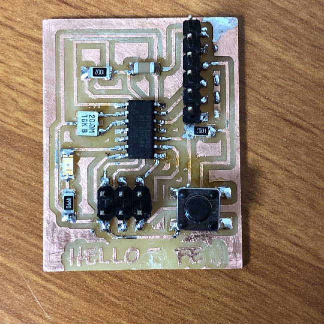
Solder the board
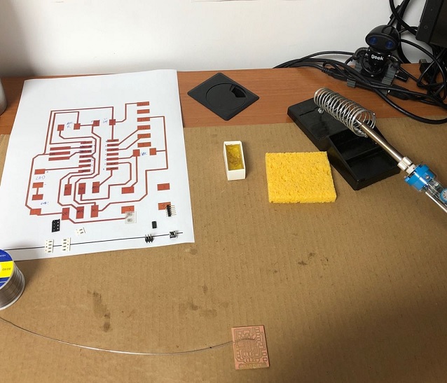
I printed the board image, wrote components information on it, checked all the materials, and then started to solder.
Some components’ requires the correct oritation.
- the IC: it has a small dot on the first pin.
- LED: the side with tiny green dot should be connected with GND.
After soldered, use a multimeter to make sure everything works fine.
Use Arduino as ATtiny Programmer
I didn’t have an ISP, lucky that I have Arduino Uno Kit. So I can use this as ATtiny programmer.
I bought this kit 6 years ago, and it haven’t been used for years. So first I tried breadboard with hole-through ATtiny85, to make sure the it could work.
I followed instructions of these two posts: 1, 2, added a resistor and an LED into the breadboard.
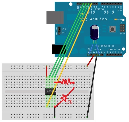
The blink example in Arduino example makes the LED blinked.
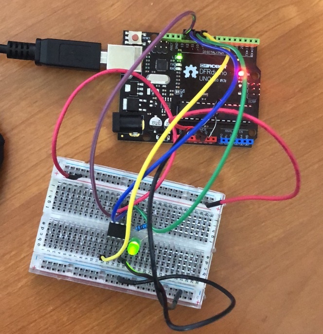
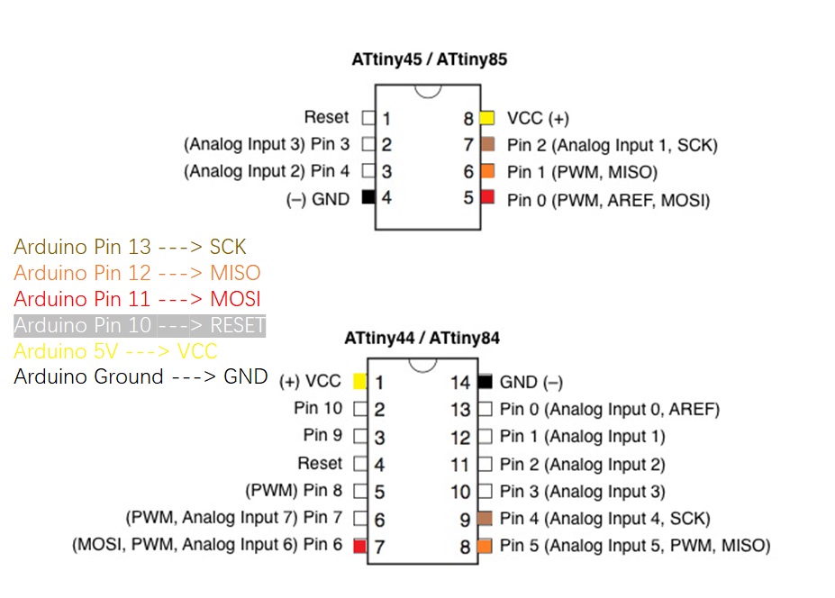
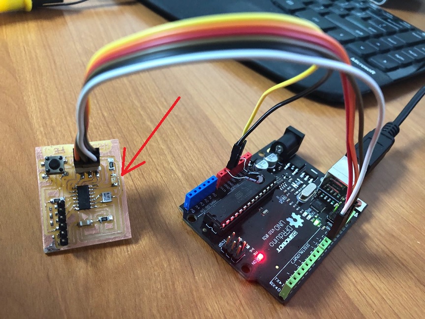
After the prototype, I connected my ATTiny hello board to Arduino. It was quite similar: the only difference I made, is to check the datasheet and change the pinouts.
Unfortunately, the LED did not shine.
I spent quite long time to check the pinouts and the solder works, but everything was just fine.
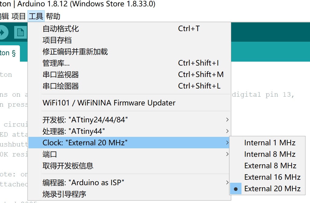
All in sudden, I realized that the board had a resonator, which is 20MHz. So it was not the default 8MHz.
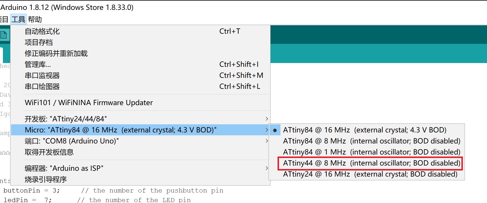
I changed to use another board manager, instead of the previous one. Then I was able to choose 20MHz external oscillator, and the LED was on.
I modified the button example in Arduino examples a little bit, and now the LED shines when button is pushed.
The Hello World Echo Program
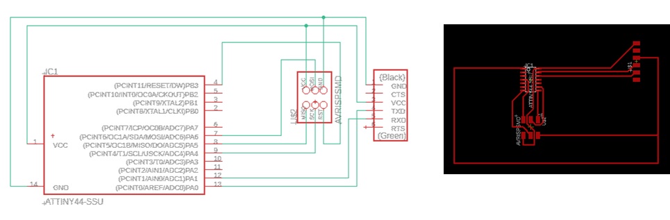
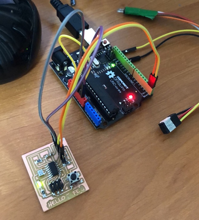
The next step is to program my tiny44 with hello.c. I use Arduino as ISP to uopload the code, then change the connection to use Arduino as USB to Serial convertor as below:
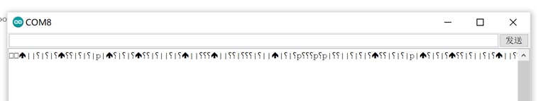
I modified the hello.c code a little to turn LED on, hence I can know the code worked. However, the serial monitor printed only messy code.
I doubt if it was because of the baud rate, as the hello.c configed the delay time for 115200 but the ArduinoISP code uses 19200.
// in hello.c
#define bit_delay_time 8.5 // bit delay for 115200 with overhead

// in ArduinoISP
#define BAUDRATE    19200
However, I tried modified the bit_delay_time, specify different boudrates in the monitor, but still no luck.
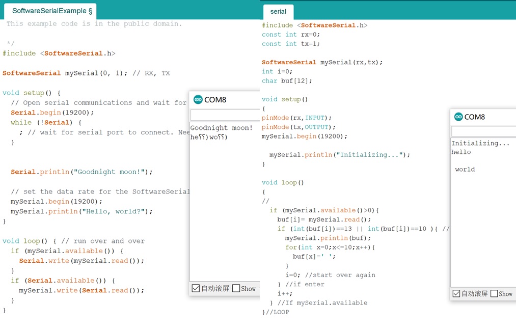
Then I use the built-in Software example. It cannot get compiled for ATTiny44, so I tried the code with Arduino Uno directly.
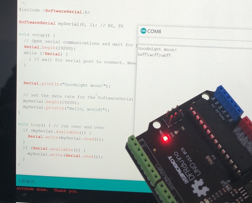 The code had some problem, and another code I found from internet worked fine. And the boud rate in the code was critical.
Then I tried the hello.c code with ATtiny44 hello board again. Unfortunately, the hello board stop working, and kept reporting the following error:
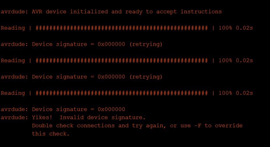
I guess it might because I clicked the burn bootloader menu by mistake, and the clock option is incorrect then. So far, the hello-board is still dead :(

related files
The schema file
The board design file
* The arduino code