11. Input devices
The idea is to design a modular board around an ATtiny84. I will need two boards for my final project, so I decided it would be best to start it here. They can be used for input, output, and networking. They will have serial debugging as well.
Design process
The design is based on hello world ATtiny44. The ATtiny44 and ATtiny84 are essentially the same chip, just the 84 has more memory. I used KiCAD to redraw the board to suit my requirements. I’ve documented the KiCAD process in a previous weeks assignment
Removing the crystal allowed me free access to the pins on the left side of the chip. In its place, I added a 2x4 pin header for power, ground, and two I/O pins. For the I/O I used pins 5 and 6. The pinout diagram shows me that those pins are PB2 and PA7 on the schematic. These equate to pins 8 and 7 on the Arduino.


After the schematic was finished, I moved to the PCB and routed all of my connections.

Then exported the black and white images for the fab mods


Fabrication process
Instead of the ShopBot desktop, I decided to use the Modela MDX15 micro-mill. I found an excellent and thorough tutorial on the Fab Academy website. I didn’t see a need to re-write the tutorial, but I will highlight some of the issues I ran into and some insights I’ve gained. I’d like to thank Eduardo Chamorro from Fab Lab Barcelona for the fantastic tutorial. I’ve included a link here:
Following the tutorial, I used Fab Modules to generate the .rml files need for the machine
Once those were saved, I started the milling process. The first few attempts did not go well. The first issue I ran into was a buffer overflow, which caused the machine to lose position and start cutting randomly.

Oops
After a few hours of testing, I determined the issue was the feedrate. I had set it to 2mm/s. My thought was to err on the side of caution. As it turned out, that was too slow. The Modela was receiving information faster than it could process, causing the overflow error. Setting this to the default of 4mm/s corrected the issue.
The second issue was not setting the home positions to the same place for the traces and cutout files.

Always check the home positions match
That was corrected by just being more mindful of the settings. I made sure that the x0, y0, and z0, positions were the same for both files.
The last issue was the copper board breaking free during the cutting process. As soon as I saw it happen, I pressed the “view” key on the Modela to halt the process. But the damage was done.
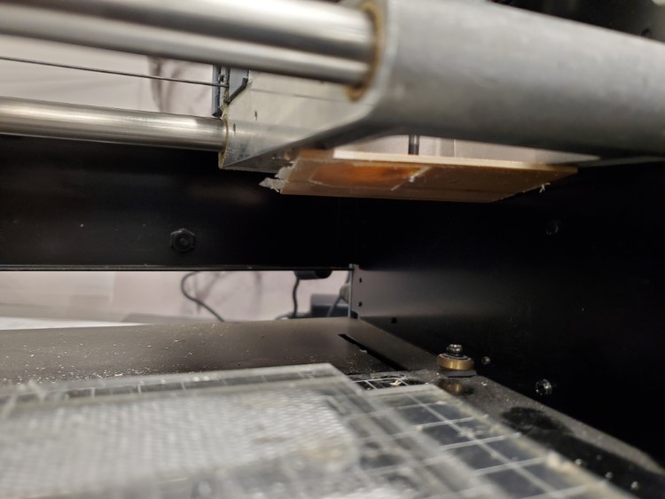
Stuck to the tool
That was corrected by making sure the spoil layer was clean, that I covered the entire board with double-stick tape, and applied it with firm and equal pressure.
Once all of that was sorted out, I was finally able to cut boards consistently.


Because of the modular nature of the boards, two were produced
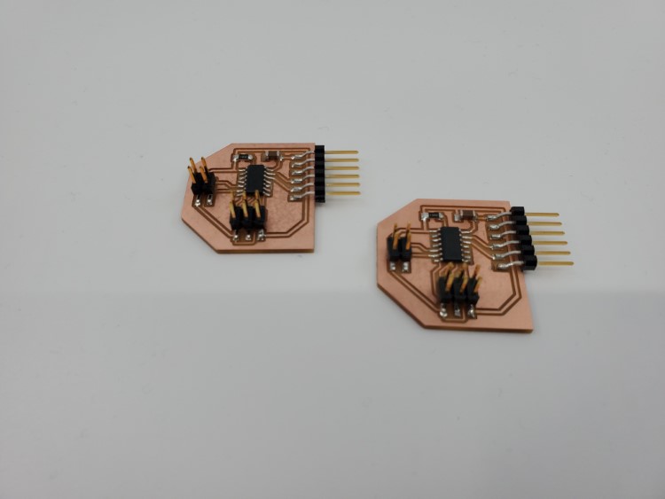
A short connection cable was made to go between them

Programming process
The boards were programmed using the Arduino IDE and the TinyISP programmer I built for the Electronics Production assignment
The first thing I needed to get working was the serial monitor. I found using a simple serial command didn’t work. After some research, I learned the Attiny84 does not have hardware serial capabilities. It has to be setup for software serial. Luckily, there is a library built into the atTinyCore board manager. I included the SoftwareSerial.h library and wrote a simple code that incrementally counts up an integer and displays value on the serial monitor.
#include <SoftwareSerial.h>
int x = 0;
void setup()
{
  Serial.begin(9600);
  Serial.println("Serial test");
}

void loop()
{
  Serial.print("x= ");
  Serial.println(x);
  delay(500);
  x++;
}
I activated the serial monitor and was presented with a set of repeating backwards question marks. That told me that the data was corrupted somehow.

At first I tried to change the BAUD rate, making sure that the values match in the code and on the serial monitor, but still got the same results.
I looked through the various settings options and found that the clock speed can be changed. The default setting was 8MHz (internal). I realized that I removed the crystal, and that might affect clock speeds of the tiny84. I found that using 4MHz (internal) did the trick.

Found under Tool=>Clock
I reloaded the program, opened the serial monitor, and watched the numbers climb.
Success!
With that working, the next step was to add an ultra sonic sensor. I’m using an HC-SR04, mostly because it’s cost effective and fairly accurate
The sensor has 4 pins; power, ground, trig, and echo. I found a simple tutorial on how to program the sensor here:
I had to make some changes to the code provided from the tutorial. I needed to change the pins to match the pins on my board. I set the trig pin to 8 (PB2) and the Echo pin to 7 (PA7).
The code also included calculations to convert the raw data to an accurate range value in centimeters. I removed those calculations so I could see how the raw data values correlates to real world distances. I also had to include the SoftwareSerial.h library to allow for the serial monitor to function.
#include <SoftwareSerial.h>    //needed for the ATtiny84
/*
  Ultrasonic Sensor HC-SR04 and Arduino Tutorial

  by Dejan Nedelkovski,
  www.HowToMechatronics.com

*/
// Modified for ATtiny84 by Christopher Leon 5/2020
// Notes: Commented out the calculation formlua to
// produce raw data from HC-SR04
// defines pins numbers
const int trigPin = 8; //PB2
const int echoPin = 7; //PA7
// defines variables
//long duration;
//int distance;
int raw; //for HC-SR04 data

void setup()
{
  pinMode(trigPin, OUTPUT); // Sets the trigPin as an Output
  pinMode(echoPin, INPUT); // Sets the echoPin as an Input
  Serial.begin(9600); // Starts the serial communication
}

void loop()
{
  // Clears the trigPin
  digitalWrite(trigPin, LOW);
  delayMicroseconds(2);
  // Sets the trigPin on HIGH state for 10 micro seconds
  digitalWrite(trigPin, HIGH);
  delayMicroseconds(10);
  digitalWrite(trigPin, LOW);
  raw = pulseIn(echoPin, HIGH);
  // Reads the echoPin, returns the sound wave travel time in microseconds
  //duration = pulseIn(echoPin, HIGH);
  // Calculating the distance
  //distance = duration * 0.034 / 2;
  // Prints the distance on the Serial Monitor
  //Serial.print("Distance: ");
  //Serial.println(distance);
  Serial.println(raw);
}
I loaded the program using the TinyISP programmer, opened the serial monitor, and ran some tests. I was getting raw data from the sensor that dropped when my hand got close and increased when I moved farther away.
Part of the group assignment was to read digital values from a sensor, so the last test was to see how the raw data values directly related to real world measurements. I set up a simple experiment with range indicators. The plan was to place an object at each of the markers and see what value the board produces. The test was setup with five distances, 6 inches, 12 inches, 18 inches, 24 inches, and 36 inches.

I used an old PLA filament box as a nice flat object

6 and 24 inches shown
Results
| Distance | Value Average |
|---|---|
| 6in | 605 |
| 12in | 1182 |
| 18in | 1728 |
| 24in | 2306 |
| 36in | 2938 |
Later, I’ll use this values to set the ranges of the various lightning animations
Files

This work is licensed under a Creative Commons Attribution-NonCommercial-ShareAlike 4.0 International License.