6. 3D Printing and Scanning
Group assignment
To test the design rules of our 3D printers, document the work, and explain the limits of our 3D printers. The results can be found here:
Printing these objects very enlightening. They were designed to test various aspects of additive manufacturing that can be difficult. Unsupported overhangs, steep angles, tight tolerances, and dimensional accuracy are all things that need to be considered. Knowing the capabilities and limitations of our 3D printers will allow for more successful printing. There were some specific things that stood out. The accuracy for outside dimensions is much better than interior dimensions. Both machines can print a large, unsupported space (bridging) well, as long as the overhang isn’t free-standing. Both machines are capable of printing assemblies with tolerances as small as 0.3mm without the parts fusing.
The advantages of 3D printing became apparent while working through this process. When developing new products, being able to have a physical model that can demonstrate fit, form, and function cheaply can greatly enhance a companies productivity. This is especially true if multiple iterations need to be produced. Standard subtractive process would require custom tooling and fixtures to produce, and would have to be modified any time a design change was made. 3D printing eliminates that. This also shows one of the limitations of 3D printing, it’s not well-suited for mass production. Additive manufacturing is a slow process. While time and money can be saved in the prototyping stage, subtractive manufacturing is still the best option for mass production. Ideally, combining the two would be the most beneficial.
Testing
MakerGear
Using the MakerGears starts with Simplify3D:

First, import the .STL file. Here, the thickness model was used:
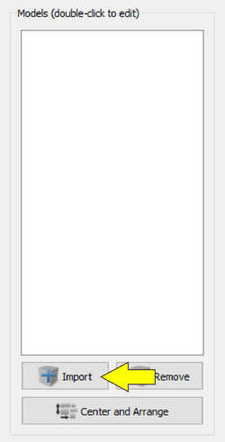

Imported model
Add the setting profile, this is called a process:

Basic settings profile:
| Variable | Setting |
|---|---|
| Layer height | 0.2mm |
| Extruder temperature | 210°C |
| Bed temperature | 70°C |
| Print speed | 60mm/s |
| Infill | 15% |
| Raft | yes |
Select the proper printer and adjust any settings as needed. Note the multiple tabs, each tab has numerous settings that can be changed, adjusted, and tweaked. For the sake of control, default settings were used:

Slice the model with the selected process using the Prepare to Print button:

This brings up the preview screen. Here, a layer-by-layer simulation can be viewed, as well as different colorings for feature types and speeds, as well as an estimage of the time, amount of material and cost of the print. Any problems areas with the print, speeds, geometry, overhangs, bridges, etc, can be viewed here:

The slicer produces G-Code for the machine to interpret, so that needs to be saved:

The saved G-Code needs to be uploaded into Octoprint. Octoprint acts as a local server that can be accessed via any web browser. This acts as the interface for the MakerGear. Homing, temperature, upoading files, telemetry monitoring and more can be performed:

Log-in to the desired 3D printer and upload the G-Code file:

Once the file is uploaded, select print:

After about 30 minutes, the print is complete :

When the print finishes, there will be an impulse to remove it. It’s best to let the bed cool for a few minutes before removing. The bed temperature is about 70°C, which is close to the transition temperature of PLA. In layman’s terms, the model is still very soft and will be damaged if removed right away.
Something of a side note, when changing out materials, be sure the nozzle is completely clean. If there is left over material, it could fall into a print, possibly causing a print failure.

It’s fortunate that this was caught early and the print could be stopped. Had it continued, the green material would have hit the nozzle and been dragged, possibly causing the entire print to lift off the bed.
3DWOX1
Using the Sindoh 3DWOX1 begins with the 3DWOX Desktop program:

First, import the .STL file. Here, the dimension model was used:


Next, select the settings profile:

As mentioned earlier, 3DWOX desktop has both an easy and advanced mode. For control, the ‘Normal Speed-Normal Quality Print’ under the Easy Mode was used:

Although they can’t be seen in the Easy Mode, here’s the basic settings profile:
| Variable | Setting |
|---|---|
| Layer height | 0.2mm |
| Extruder temperature | 200°C |
| Bed temperature | 60°C |
| Print speed | 40mm/s |
| Infill | 15% |
| Raft | yes |
Slice the model by selecting the slice icon:

Once the slice is complete, a preview screen appears:

This screen provide a simple interface to simulate the build process. The features (infill, perimeters, bridging, etc) are color-coded for easy troubleshooting.
Next is to save the G-Code to a USB flash drive:

Remove the USB flash drive and insert it into the 3DWOX1. The next steps involve navigating the simple interface to load and print the model:

Select PRINT to access the USB flash drive
Select the gcode folder
Navigate to the file
The screen will load with a preview, and show the dimensions in millimeters. Press the play icon
Once the print completes, the printer beeps a few times and displays an option to remove the print:

The print bed moves forward for easy access to the print:

An interesting feature of the 3DWOX1 is the magnetic, removable print bed. This print bed is also flexible, which assists in the removal of the print:
Caged Water
For the individual assignment, we had to design and 3D print an object that couldn’t be easily made with subtractive methods. I decided to make a small art piece I like to call, Caged Water. It’s a water molecule suspended in a stylized cage. I don’t think this object would be possible with subtractive methods. There are undercuts, parts that require turning, and geometries that would be inaccessible to machine tooling.
I decided to use Solidworks for modeling, as I’ve learned quite a lot about its work-flow through previous weeks’ assignments and documentation.
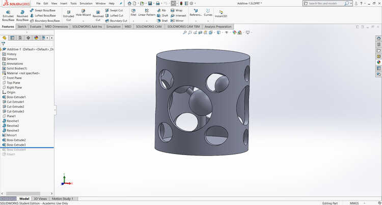
Solidworks:
Render:

Reality

3D print was done on the Stratasys F370. Material is ABS.
Digital chair
Part of this weeks assignment was to take the digital and make it physical. The other part of is to take the physical and make it digital. This is the process of 3D scanning. There are multiple 3D scanners on the market today, ranging in price from $100 to $1 million. I thought it would be interesting to use something on inexpensive side of the spectrum. I ended up using a Knockout Concepts KS-1.
The hardware for this device consists of two off-the-shelf parts; an Android tablet and a Microsoft Xbox Connect. The original use for the Xbox Connect was for motion-tracking games on the Xbox game console. It works by using an infrared point-cloud to measure distance and shape. It also has a full-color camera, so it can capture images as well. Knockout developed a software suite that interpreted the point-could to make a 3D model, then use the color camera to overlay the detail. The software is capable of exporting in a number of different formats, including .stl, .ply, and .obj.

I decided to scan a small rocking chair we had in our lab. It has complex geometry, overhangs, and it’s got a lot of color:
The process is simple. Open the scan software on the tablet, press the scan icon, and walk around the object. The software gives visual indicators similar to a heatmap for the scanning progress. Un-scanned parts show red and gradually move through yellow and then green to indicate fully-scanned geometry. Once it’s scanned, a full-color model is produced. From here, it can be saved in the desired file type, in my case, .obj.
Resolution is a weakness of this scanner. The model had some large holes that needed to be fixed. I used MeshLab to fix the model and fill in the holes.
Once that’s completed, I exported the fixed model as an .obj and uploaded it to SketchFab, where I embedded it below.
The model
Files

This work is licensed under a Creative Commons Attribution-NonCommercial-ShareAlike 4.0 International License.