3. Computer Aided design
The goal for this week is to use various 2D and 3D CAD packages to design, model, render, animate, and simulate a possible final project.
2D
Two-dimensional CAD packages are separated into two different styles; raster and vector. Simply put, raster is pixel based editing, while vector is using lines and arcs. Like anything else, they both have advantages and disadvantages. Raster is typically used for photo-editing and web graphic design. Almost all graphics found on the web are pixel-based, so understanding how to edit and manipulate these images is very useful for web-design and photography. One advantage pixel based graphics has is their ability for the files to be compressed to save memory. Another is their near universal file types. One big disadvantage of pixel based designs is that they cannot be scaled to large dimensions while maintaining quality and resolution.
Vector designs are comprised of lines and arcs. They are generally used for large format graphics, technical drawings, and designs that will be used for CNC cutting. One advantage of using vectors is they can be scaled infinitely without loss of quality or resolution. Another is vector lines and arcs contain meta-data about the direction of the lines. This is why vectors are used for CNC applications. Unfortunately, vector files aren’t always universal. Most are specific to the software being used. There are a few interchange files that software can export and import. Occasionally data, such as size, can be lost or corrupted.
Raster - GIMP
For the raster portion of this project, I decided to use GIMP. I didn’t know much about it prior to using the software. All I knew it is free, open-source, and extremely powerful. To start, I went through a simple tutorial I found on the GIMP website:
With this I designed an image I’ll use for my youtube channel:

Once I figured out the basic work flow of GIMP, I started on creating a render of a cloud.
First, open a new file and set the dimensions of the work area. In this case 500 x 700 pixels. Notice that the DPI was changed from 300 to 72, this is to allow for a smaller file size.

Set foreground and background colors by clicking on the two colored squares in the toolbox. Used a dark grey instead of black to add a touch of realism:

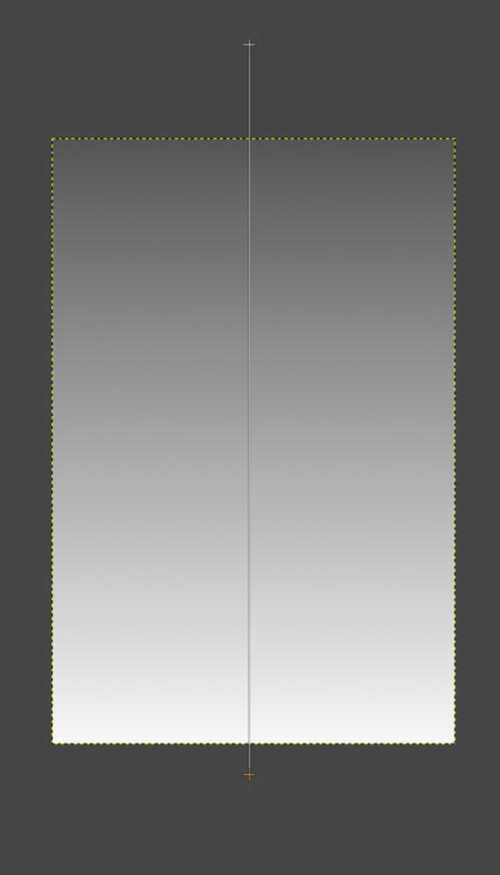
Select the gradient tool:

Fill gradient from top down. Left-click and drag selection. The gradient will be based on the foreground and background colors selected. The intensity and direction of the gradient is based on the distance of the starting and ending points.
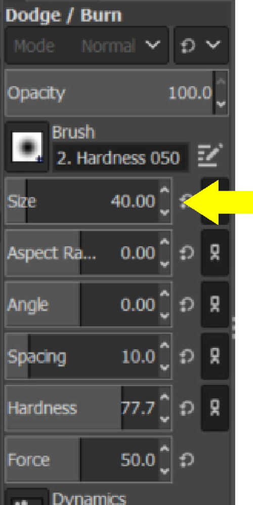
Burn/dodge tool is used to make general cloud shape. The tool is used to selectively lighten or darken depending on the option chosen:

Set the desired brush size:

The mouse pointer speed was set too high and made this task difficult. I had to slow it down to make it more manageable. Moving around in one continuous motion without letting go of the mouse button keeps the effect uniform
Switching to the smudge tool:

is used to ‘fluff’ cloud. Be sure to not over do this, just breaking the edges is enough:

Switch back to the burn/dodge tool and repeat for smaller cloud on inside the original. Reducing the brush size makes this step easier: .

Letting go of the mouse button and restarting increases the effect when overlapping the existing dodging
Again switching to the smudge tool, repeat:

Be careful not to hit the outer part of the cloud and ruin the previous work
Repeat as needed:

Now finish the rendering
First, add new layer:
CTRL + SHIFT + N or got to Layer >> New Layer…
Set fill to transparency:
![]()
Go to rectangular selection tool:
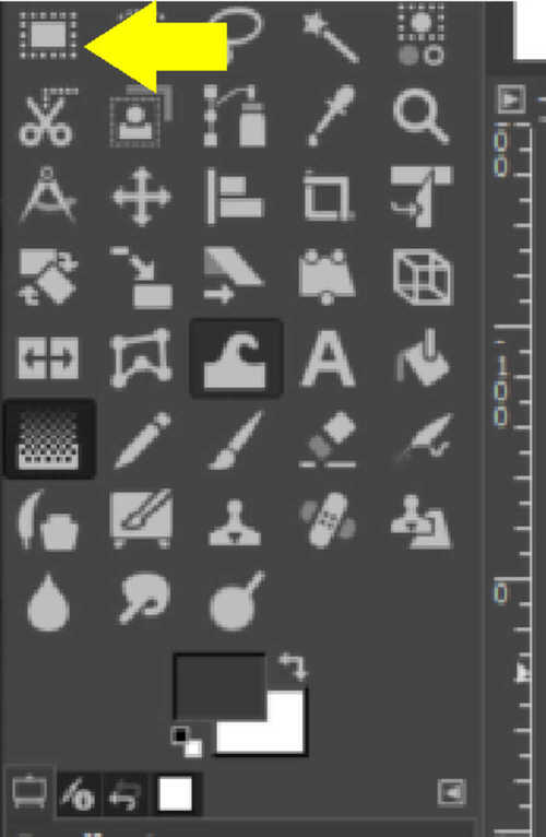
Left-click and drag a box:
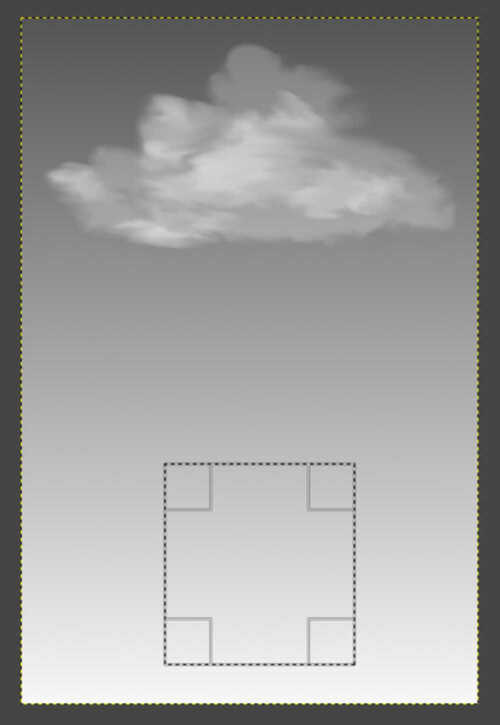
Select bucket fill tool:

Select pattern fill and wood template:

Fill the selection:

Repeat for the post using a gradient to simulate aluminum:
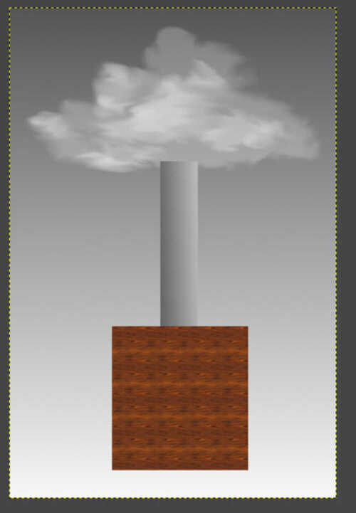
The render is very simplistic, highlighting one of the weaknesses of raster based software for technical drawings.
Vector - CorelDraw
For the vector portion, I chose Coreldraw. This is mostly due to it being a standard used in most FabLabs.
Like every other software, create new document. The document size was changed, in this case, 24” x 24”.

Turning on snap to objects is always helpful for moving geometry around:
Alt + Z
Create a box to represent the base of the lamp:

Rectangle tool
Left-click and drag a box:

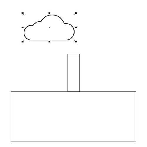
Resize the box to real-world dimensions:
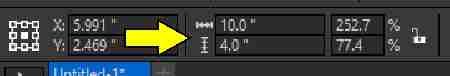
Draw another box to represent the post and resize:

Pick Select tool. The select tool is a very important tool in Coreldraw. It’s the goto tool if the software isn’t behaving as expected:

Select smaller box and bring cursor to the middle of the bottom line. The cursor will indicate ‘midpoint’. This is where the usefullness of ‘snap to objects’ shows.

Left-click and drag to midpoint of top line of larger box. Corel will ‘snap’ the midpoints when it gets within a few pixels:

I found a simple, transparent cloud clip art here:
I then imported it into my document File >> Import or CTRL+I

Select the file and left-click any where to import the image:
With the cloud object selected, left click and drag any of the corner handles (one of the black boxes on the corners) to quickly resize:

Reposition using the pick tool just as before. Object is in front of the smaller box.
I plan on using an HC-SR04 ultrasonic sensor for range-finding and wanted to include it on this render. I found an image online and imported it just as I did the cloud clipart:

Import, size, and position the image as before:

Fill in the boxes with color. Select large box with pick tool. Move cursor to the color palette on the left side of the screen and left click the color choice, in this case orange:

Do the same with the smaller box but in grey.
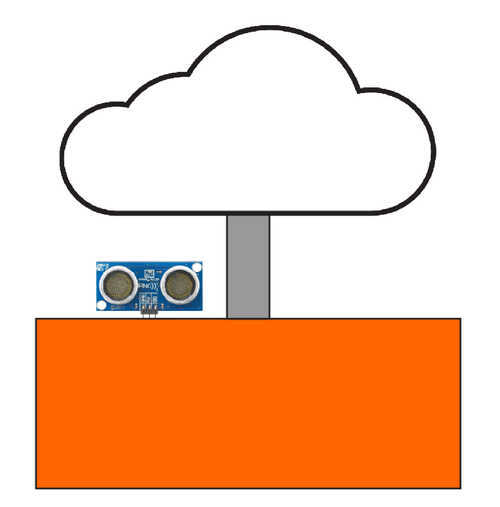
Another simplistic representation of a possible final project. CorelDraw is more of a vector based art program than a technical drawing program, but it still can be an effective tool.
3D
SolidWorks - Design
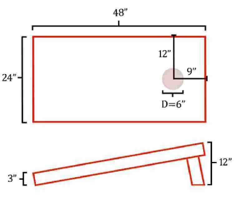
We’re extremely to receive a very powerful academic edition to use for Fab Academy, so when it came time to decide on a 3d modeling software package, SolidWorks was an easy choice. SolidWorks is also used in industrial and commercial fields, so having knowledge of how to use this software can also be a lucrative decision. At this time, I decided to change my final project to something different. The angry cloud/peaceful cloud is still something I’d like to build in the future, but I’m going with a set of cornhole (bag toss) gameboards. They will have folding legs, illuminated surface features, and will animate lights when a bag is scored.
To start, create a new Solidworks document. There a a number of different options, but for this, select ‘part’:

This is the main working screen for SolidWorks. There are many different parts to this program, so breaking it down is a good place to start:
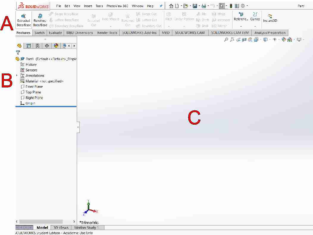
| Legend | Description | Explanation |
|---|---|---|
| A | Features tab | Switching between various tools, 3d features, sketching, rendering, etc |
| B | Features tree | Displays the sketches and features in order they were created |
| C | Part window | Where all the designing takes place |
Features tab reveals the features toolbar. This is where the 3D features such as extrusions, cuts, revolves, and sweeps are added:

Sketch tab reveals sketch toolbar. Here is where geometry, dimensions, constrains, and relations are found:

Everything in SolidWorks begins with a sketch. To start a new one, select Sketch from the sketch toolbar. That sketch will need to be placed on a surface or a plane. In this case, the right plane:

Select the line tool from the sketch toolbar. Starting at the origin, left click and release and drag a line. Left click again to create and endpoint. While on that point, left click and release again, dragging another line segment. Continue until a box shaped is formed with the rough angle of a cornhole board.
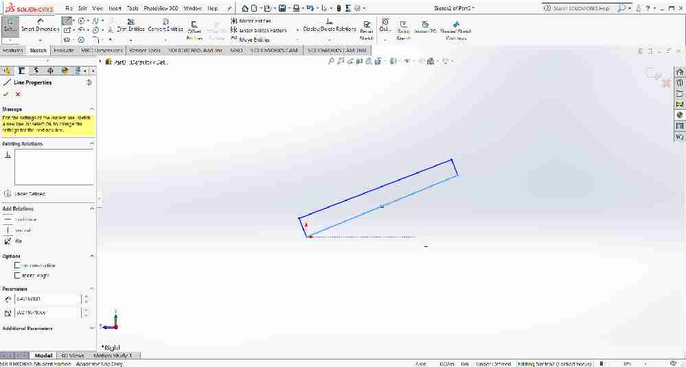
Being parametric, SolidWorks relies on constraints and relations. To add these, select the two longer lines while holding the shift key. Selected the make parallel relation.

Repeat this step with the smaller lines, making them parallel to each other. Next, select two of the adjacent lines and choose the make perpendicular relation.

Adding a construction line on the x-axis will act as a reference and stand in for the floor. To do this, select the line tool, change the construction and infinite length options. Starting from the origin, left click and drag the line until it ‘snaps’ to the horizontal constraint.
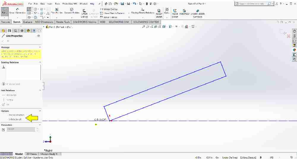
One of the constraints that needs to be added is dimensioning. On the sketch toolbox, select the Smart dimension tool. Left-click the short line and give it a dimension of 4”. Do the same with the long line and set it to 48”. Next, dimension from the construction line to the top most corner of the box. Set this to 12”.

Notice all the lines are now black, this indicates the sketch is fully-defined.
Generating the three-dimensional object requires an extrusion, based on the sketch. Change to the features tab and select extruded boss/base. Use the drop-down box under Direction 1 to change to mid-plane and set the depth to 12”.

Renaming the features in the feature tree helps keep things organized:
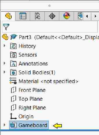
The underside of the gameboard needs to be hollowed out, or shelled. First, in the drawing area, click the scroll wheel on the mouse and rotate the object to see the backside face. Next, select the Shell feature in the feature toolbar. Set the parameters to 0.75” and turn on the show preview option. Select the green check to complete:

To reset the veiw, press the spacebar to open the orientation toolbox and select the dimetric option.

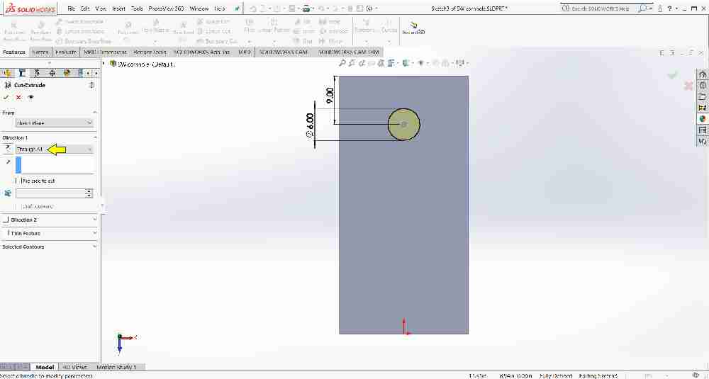
The gameboard needs a hole for the bag. To add this, switch to the sketch tab, select the circle tool, then choose the top face of the board. CTRL+8 on the keyboard will set the correct view. Draw the circle and dimension, just as before. To center the hole vertically, select both the center point of the circle and the origin and use the make vertical relation.

Using the sketch, its time to make the hole. Switch to the features tab and select the extruded cut option. Use the drop-down box under direction 1 to Through All. Select the green check to complete:
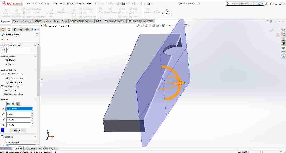
 Adding the legs requires access to the inside face of the underside. To access this, select the section view. Under Section 1, select the Right Plane:

The sketch process is the same as the others. Rotate the object, select sketch, choose the inside face, add the geometry, dimension, and rename in the feature tree:


When extruding, de-select Merge result
To add the second leg, just mirror the first. Under the features tab, select mirror, set the mirror face/plane to the right plane, and select the leg in the Bodies to Mirror section:
 Repeat process again to add holes for the hinges:

Adding the appearance of wood adds to the realism. To accomplish this, select edit appearance, then select organic; wood; polished beech:


The final details consist of adding channels for the lights and some decorative holes on the sides for some weight reduction. This process is the same as the others; adding a sketch to a plane, constraining and relating, dimensioning, extruding or cutting, renaming, and adding the proper appearances:

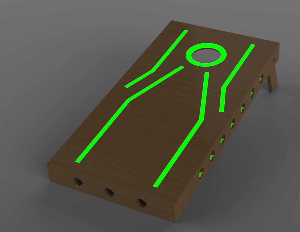
SolidWorks - Render
After a full render, showing the illumination:
SolidWorks - Animate
A brief animation showing the leg mechanism folding:
Files

This work is licensed under a Creative Commons Attribution-NonCommercial-ShareAlike 4.0 International License.