W09 - Input Devices
1. Weekly Assignments ( -> what I did this week )
-
Group assignment
-
Probe an input device(s)’s analog and digital signals
-
Document your work (in a group or individually)
-
Individual assignment
-
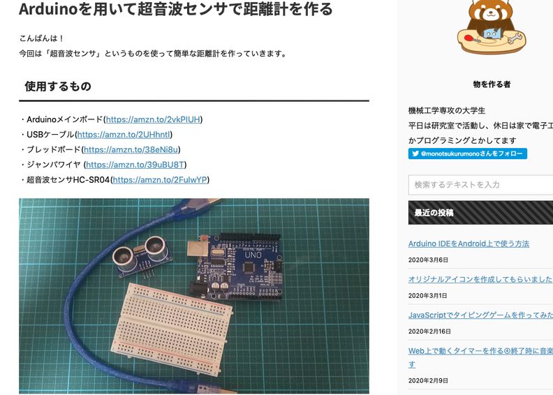
Measure something: add a sensor to a microcontroller board that you have designed and read it.
( -> I checked the sensor outputs such as, “photo resistor”, “ultra-sonic distance sensor” and “thermistor”. And for “thermistor”, I made ESP32-based PCB, and check the temperature data via BLYNK BLE from iPhone. )
Have you?
Questions from “Fab Academy 2020 Assignments and Assessment 
( -> my answers )
-
Linked to the group assignment page ( -> yes )
-
Documented what you learned from interfacing an input device(s) to microcontroller and how the physical property relates to the measured results ( -> yes )
-
Documented your design and fabrication process or linked to previous examples. ( -> yes )
-
Explained the programming process/es you used ( -> yes )
-
Explained problems and how you fixed them ( -> yes )
-
Included original design files and source code ( -> yes )
-
Included a ‘hero shot/video’ of your board ( -> yes )
2. Group Assignment Link
3. Works, steps and some details
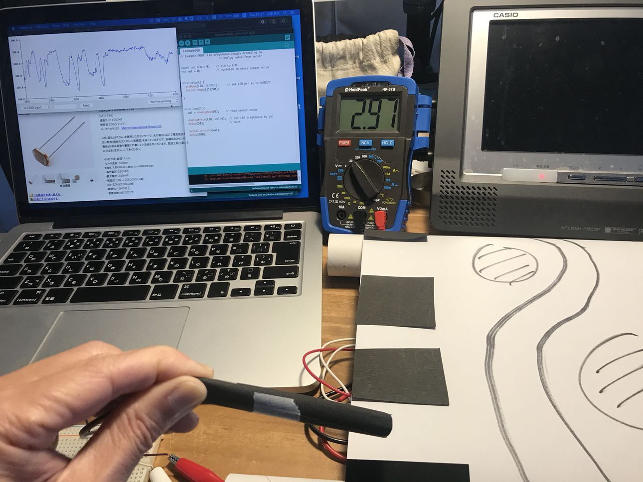
1) check the photoresistor ( CdS ) output by Arduino Serial Plotter, and control the LED brightness.
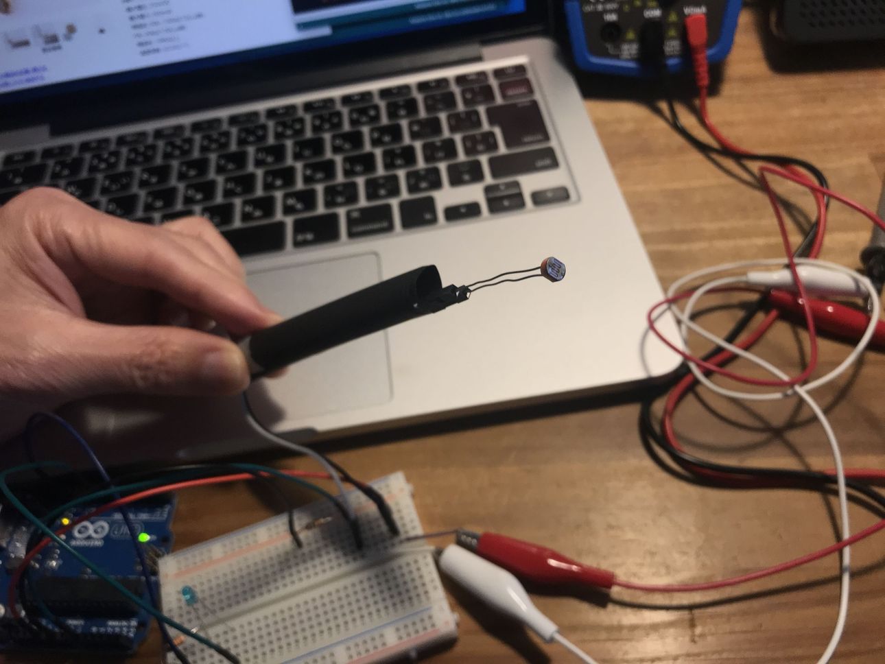
CdS info “MI516”
According to the datasheet, CdS resistance changes like below.
resistance ; 0.5 M ohm @ dark, 5 to 10 K ohm @ light (10Lux)
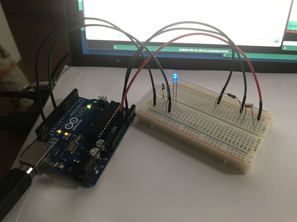
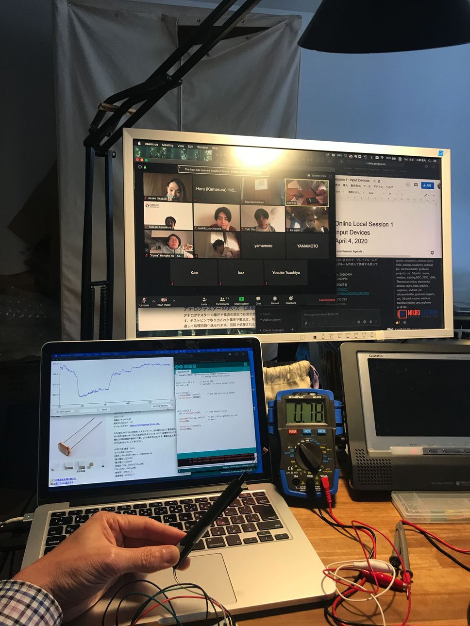
So, I connected CdS and Arduino UNO via 10k ohm voltage divider on breadboard ( 5v power supply was from USB of MacBook ).
then, observed the signal change on serial monitor on Arduino IDE.
“Example06B.ino”
( although LED was not needed for this test, I used the existing program. )
// Example 006B: LED brightness chages according to
                        // analog value from sensor

const int LED = 9;    // pin to LED
int val = 0;          // variable to store sensor value


void setup() {
  pinMode(LED, OUTPUT);     // set LED pin to be OUTPUT
  Serial.begin(115200);

}


void loop() {
  val = analogRead(0);    // read sensor value

  analogWrite(LED, val/4);  // set LED brightness by val
  delay(10);                // wait

  Serial.println(val);
  delay(100);

}
 |
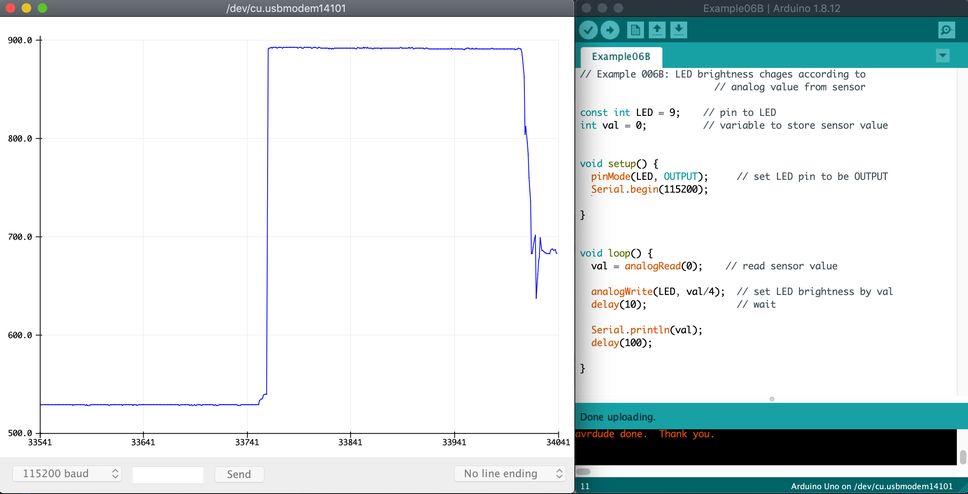 |
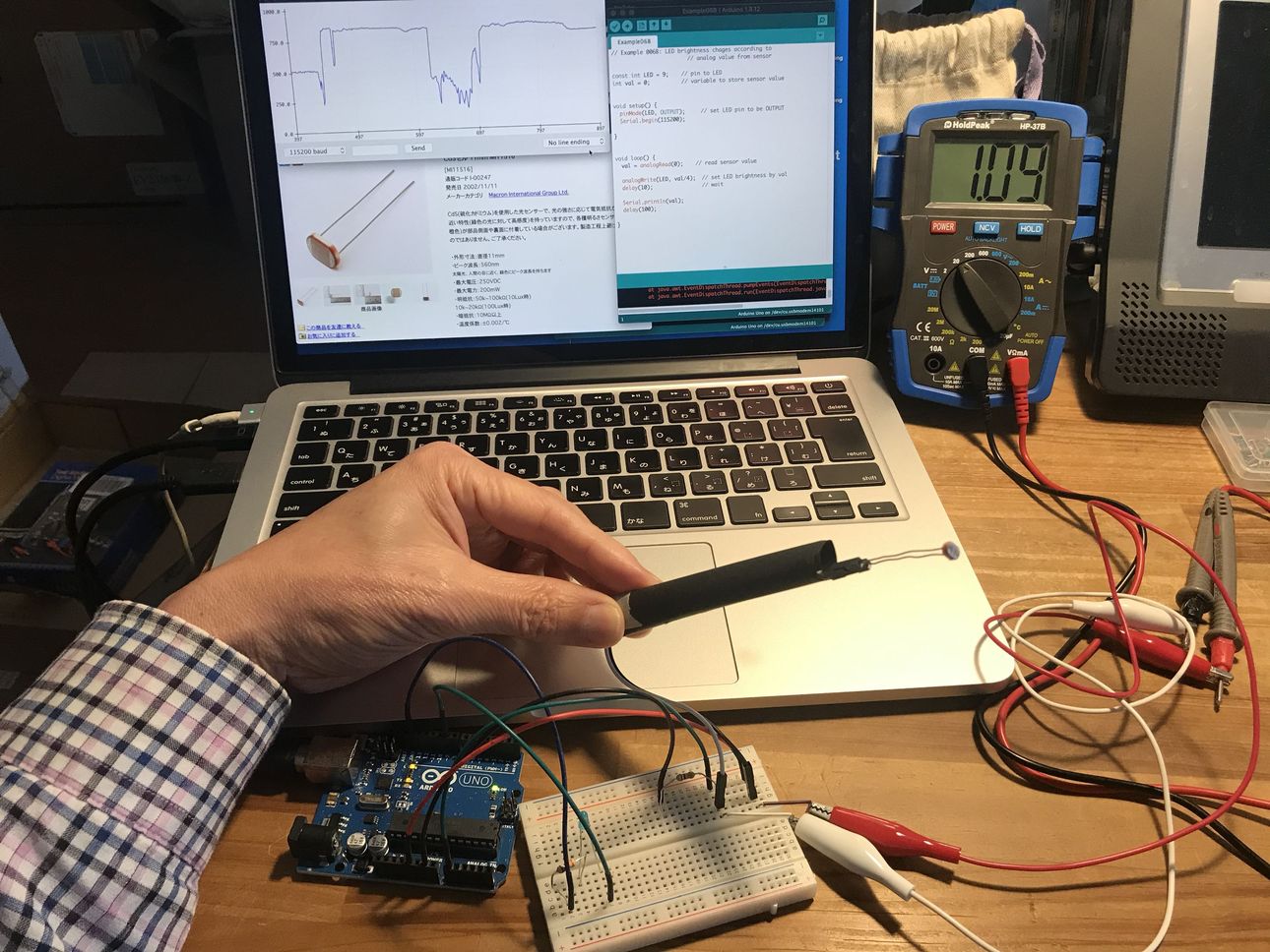
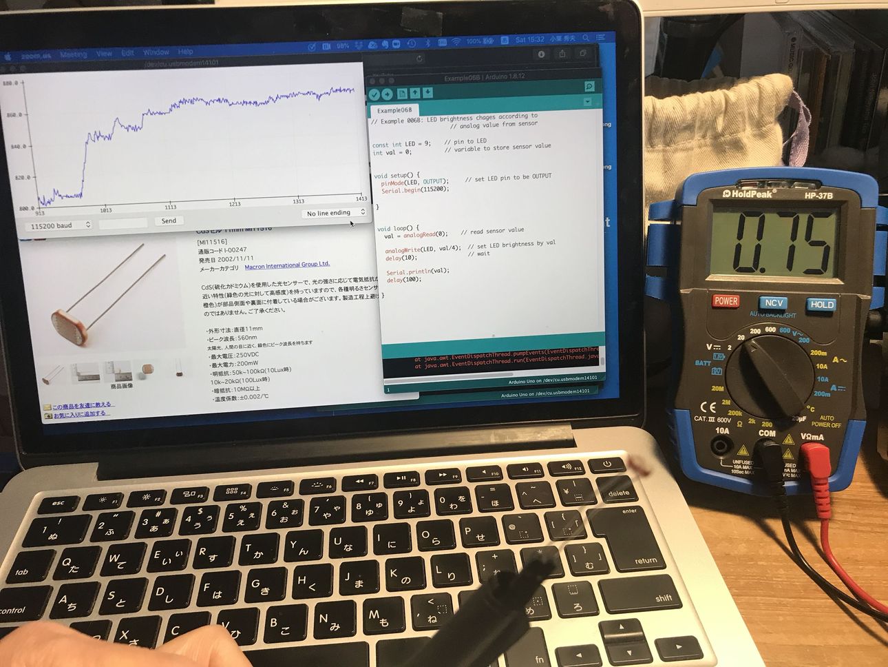
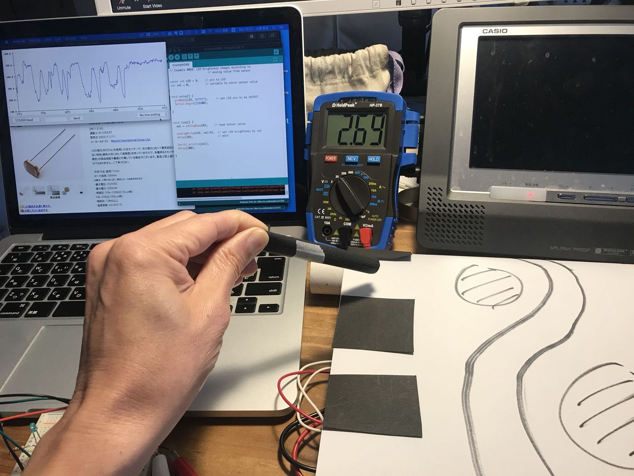
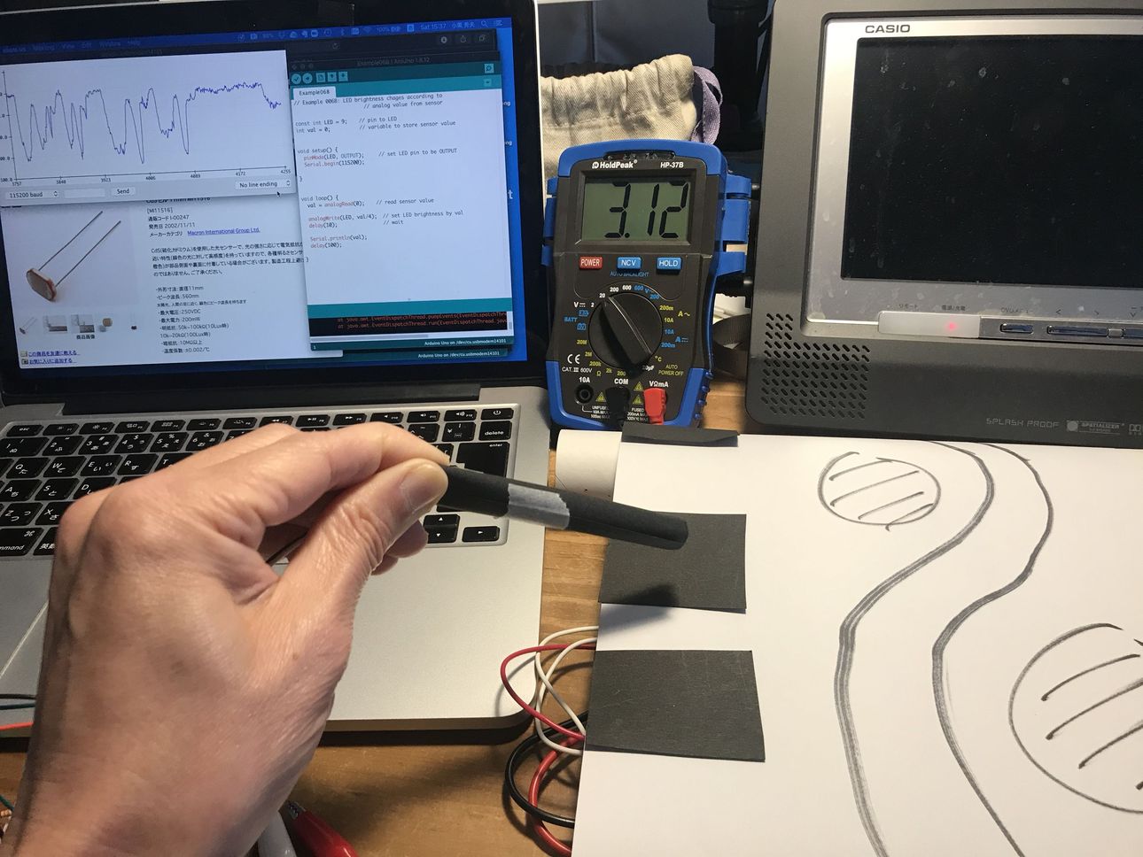
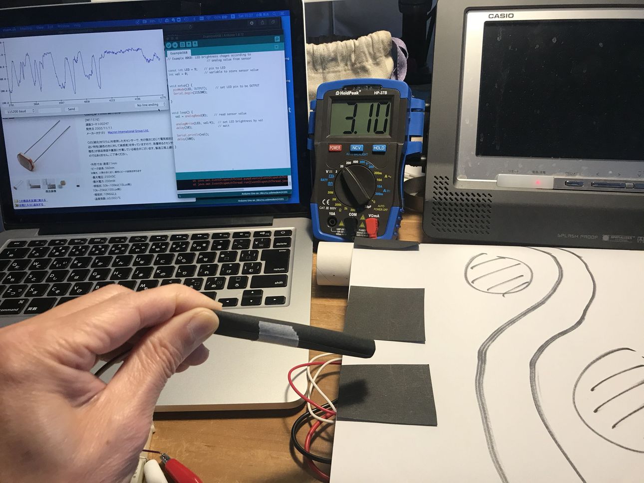
Then, I checked the CdS voltage.
 |
 |
| 0.75 V @ light (about 830 on serial monitor) | 5.06 V @ dark (about 0 on serial monitor) |
|---|---|
 |
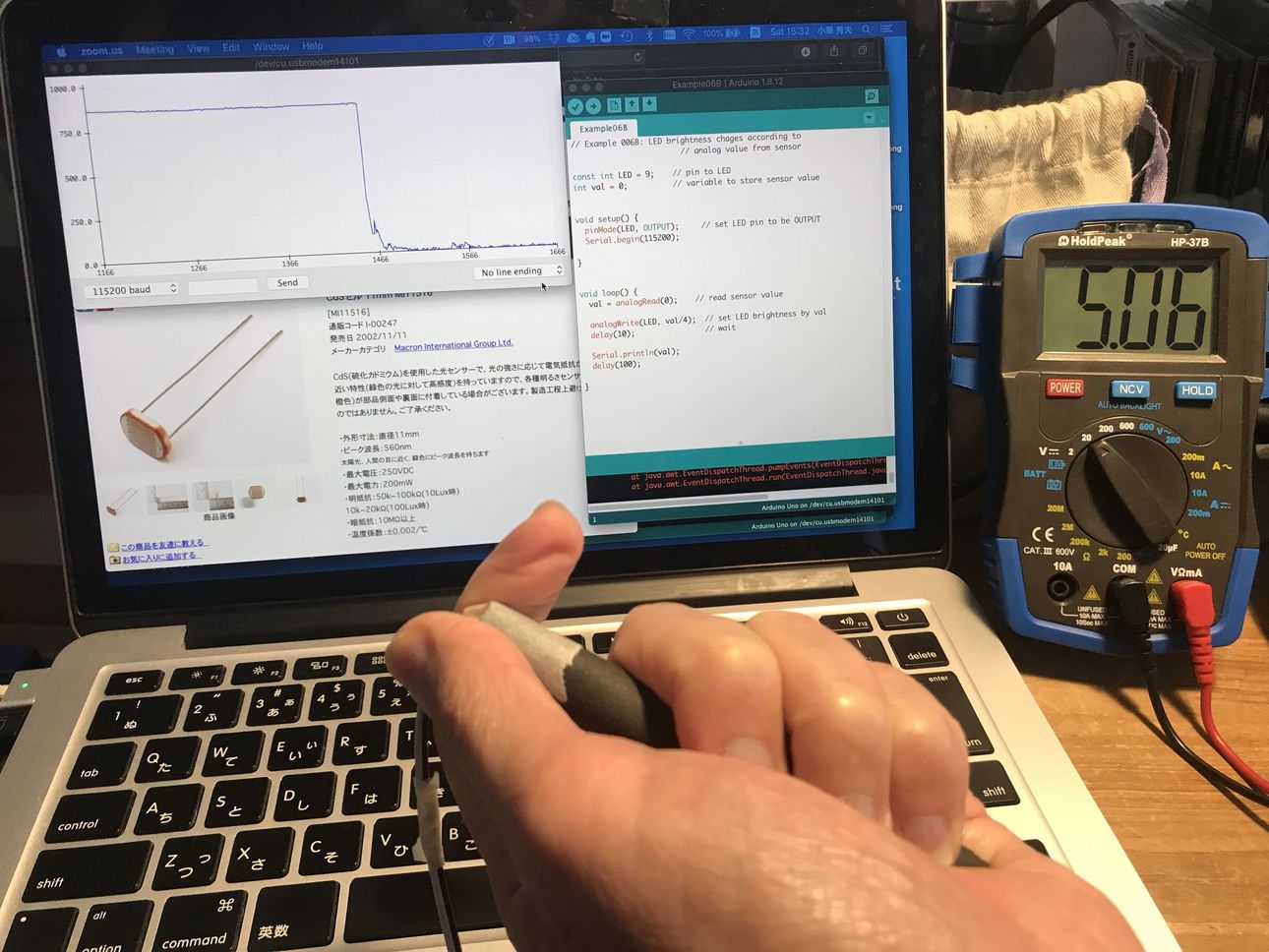 |
Although the Lux of light condition was unknown, considering the power source voltage (5 v) and resistance of voltage divider (10k ohm), the measured resistance of the CdS were as follows.
| data sheet | measured | ||
|---|---|---|---|
| Dark | Voltage | N/A | 5.06 V |
| Resistance | 0.5 M ohm | (infinity) (*1) | |
| Light | Voltage | N/A | 0.75 V |
| Resistance | 5 - 10 k ohm | 1.8 k ohm | |
| (10 Lux) | ( unknown) (*2) |
(*1) This was depending on the voltage measurement accuracy.
(*2) It is considered that the condition which seemed to be lighter than 10 Lux caused the resistance lower than 5 k ohm.
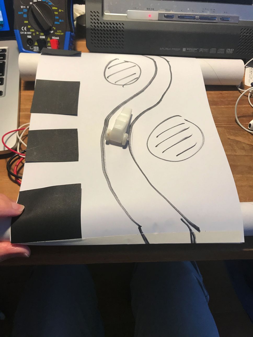
For my final project, I tried the drive simulator paper course + 3d-printed car.
 |
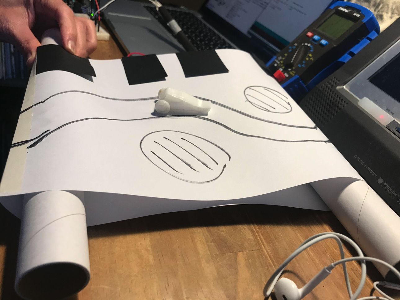 |
By putting the black & white band (track) on the side of course of Drive simulator, CdS output changed, and this could be used as the “slope” control of the course.
 |
 |
 |
 |
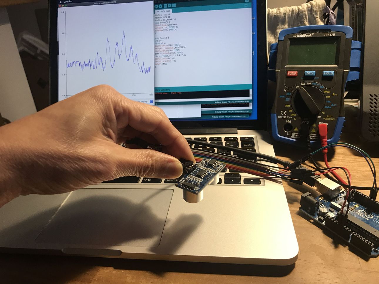
Then, I tried ultra-sonic sensor HC-SR04
, referring this site.
“Making distance meter using Ultra-sonic sensor & Arduino”
HC-SR04
“HC-SR04_test.ino”
#define TRG 10
#define ECH 11
#define HIGHTIME 10
void setup() {
Serial.begin(9600);
pinMode(TRG, OUTPUT);
pinMode(ECH, INPUT);
}

void loop() {
int diff;
float dis;
digitalWrite(TRG, HIGH);
delayMicroseconds(HIGHTIME);
digitalWrite(TRG, LOW);
diff = pulseIn(ECH, HIGH);
dis = (float)diff * 0.01715;
Serial.print(dis);
Serial.println("");
delay(100);
}
diff = pulseIn(ECH, HIGH); is measuring the elapsed time (micro seconds) between the emission and reflection of the ultra sonic.
dis = (float)diff * 0.01715; is converting “diff” to distance (cm), using sound velocity 343 m/sec @ 20 degC, which means 171.5 m/sec (half of “round trip” reflection), equals to 0.01715 cm/micro sec.
 |
Although the test was performed only in the range of 3 to 6 cm, the result was reasonable.
2) Thermistor + ESP32 ( on 2020/07/20 )
2-1) system configuration & PCB design on Eagle CAD
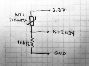
a. sensor NTC thermistor
NXFT15XH103FA2B050 ( 10kohm )
“resistor vs temperature” calculation link
b. MCU ESP32
c. display BLYNK BLE (iPhone)
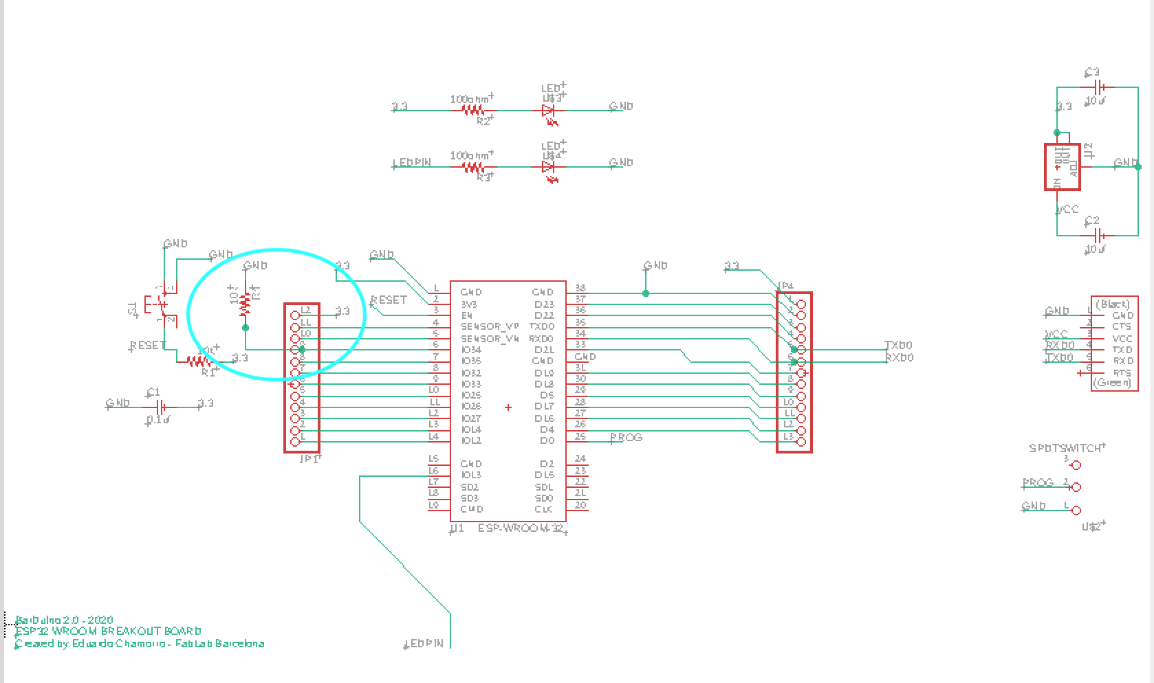
Regarding the PCB design, I modified ESP32-based “Barduino 2.0” as follows.
(1) add 10k ohm resister between GND and GPIO34, so that it can work as a voltage divider for thermistor.
(2) add 1 pin on the Pin Header to supply 3.3v for thermistor.
(3) change the position of the slider switch to the side of FTDI connector for the better packaging.
(4) delete 1 set of the Pin Header for “GPIO2 - GPIO13”
“Barduino, fablab Kamakura” link
Simple circuit diagram of the thermistor portion.
EAGLE CAD SCH image, light blue circle shows the modified portion of the above (1) and (2).
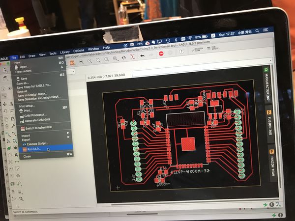
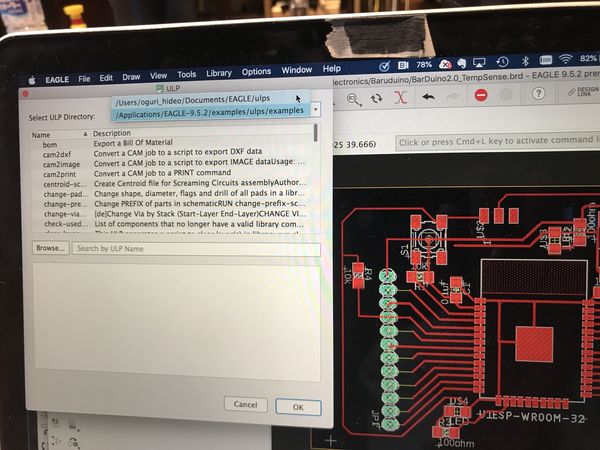
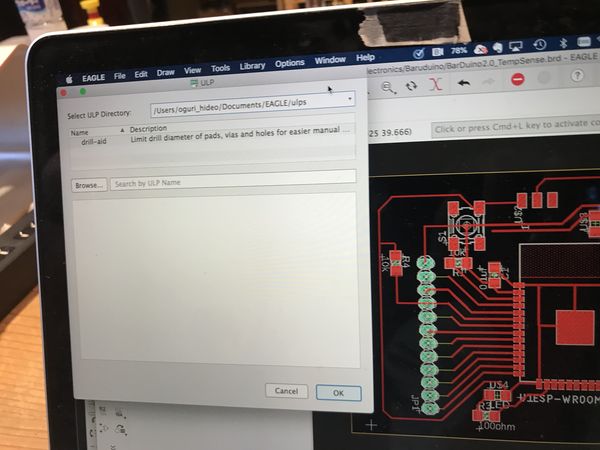
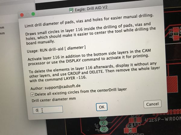
To make the drill holes for the pin header, I used the ULP (User Language Programs) from “file” -> “run ULP.... “, then, selected “Drill AID V2”, and set the “Drill center diameter” as 0mm.
| select ULP… | select “Drill AID” |
|---|---|
 |
 |
| set the “Drill center diameter” as 0mm | |
|---|---|
 |
 |
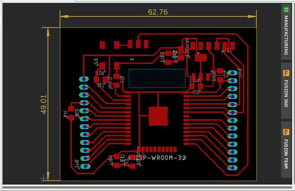
PCB image on EAGLE CAD
 |
2-2) PCB milling on CNC, & stuffing
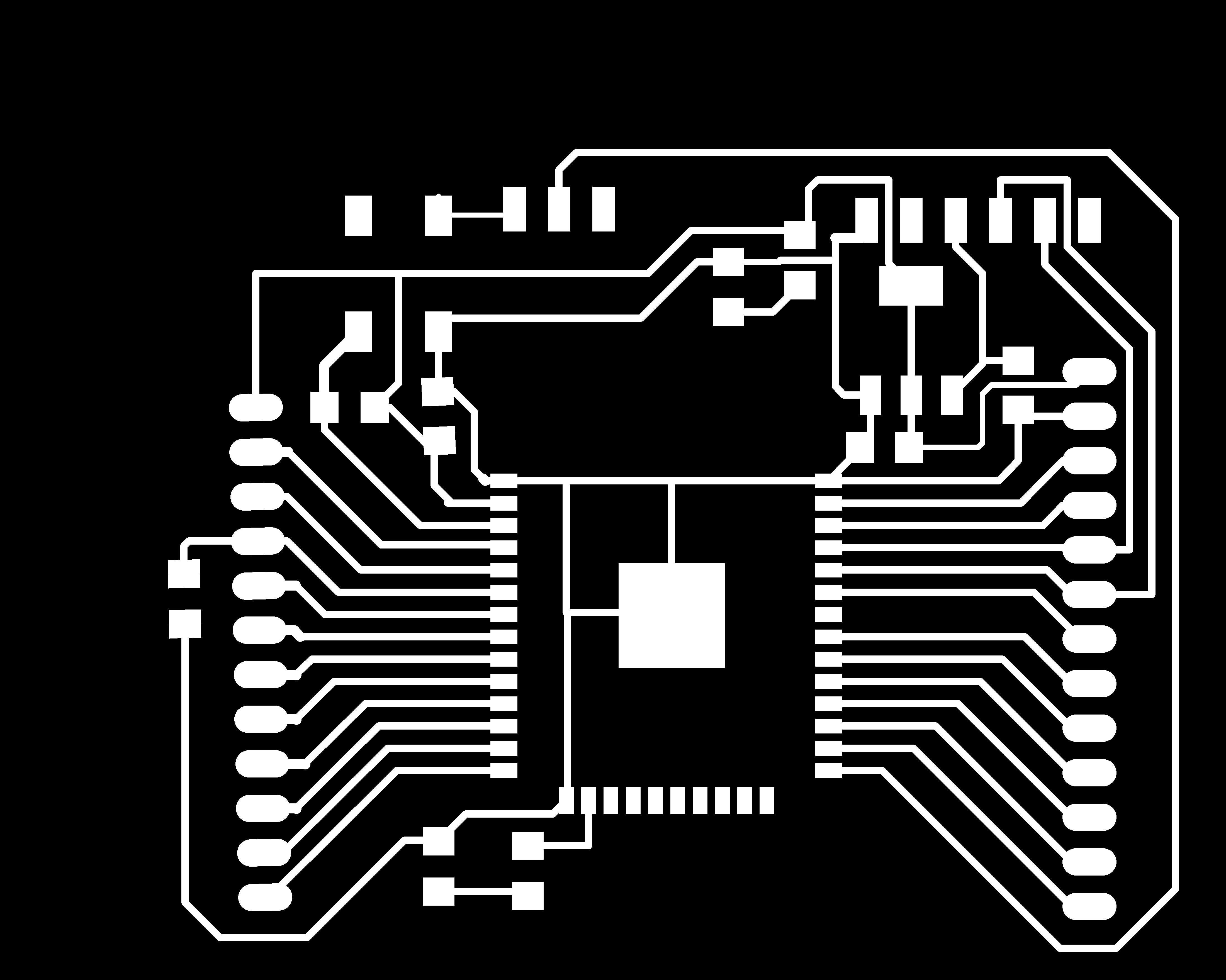
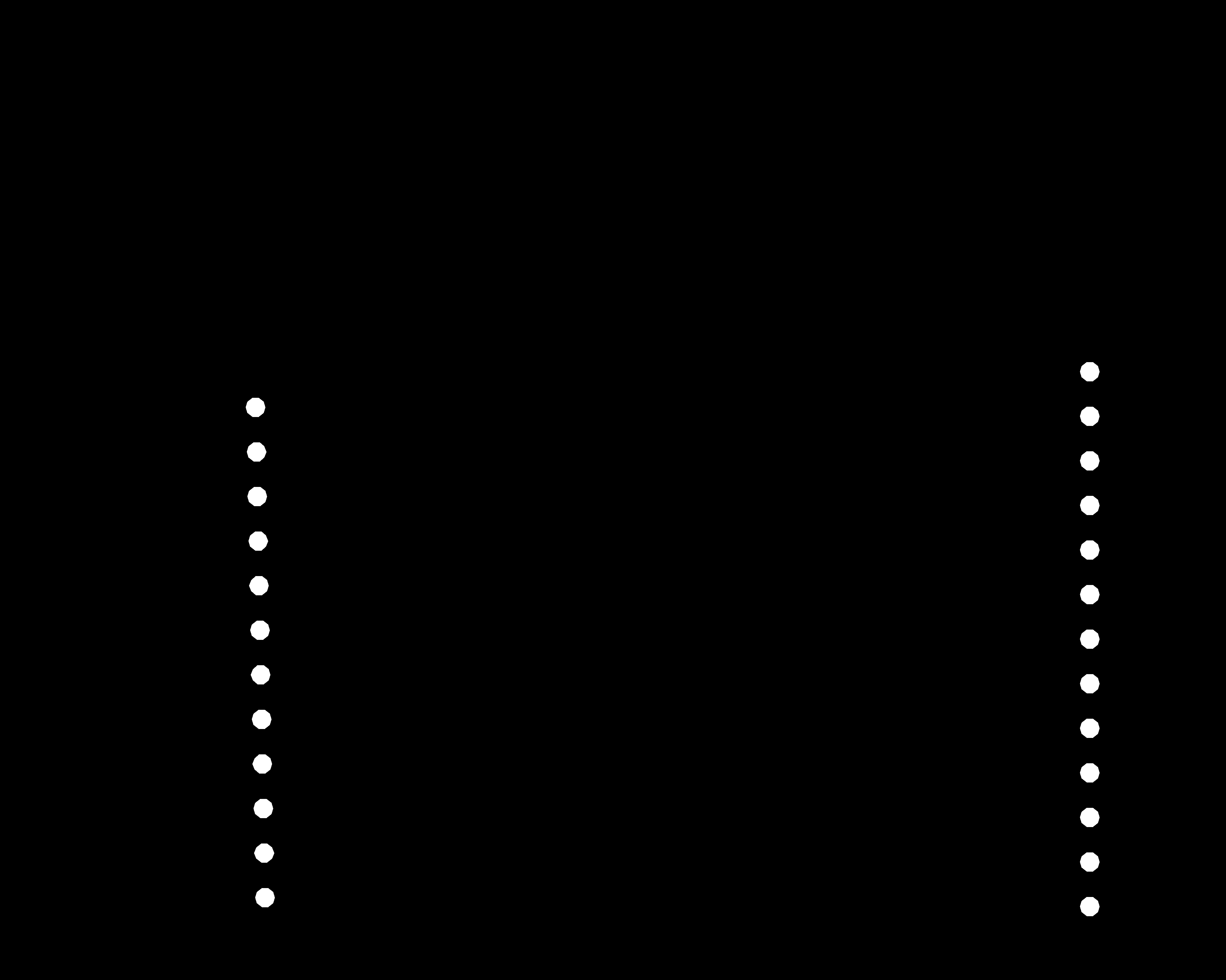
Export the image files as png, 800dpi, monochrome.
“file” -> “Export” -> “image”
| png file for “Pattern” | png file for “drill holes” |
|---|---|
 |
 |
| png file for “Antenna” | png file for “outcut” |
|---|---|
 |
 |
CNC parmeters for circuit pattern
tool diameter (in) ; 0.0156 (1/64)
cut depth (in) ; 0.004
max depth (in) ; 0.004
offset number ; 4
milling speed ; 4 mm/s
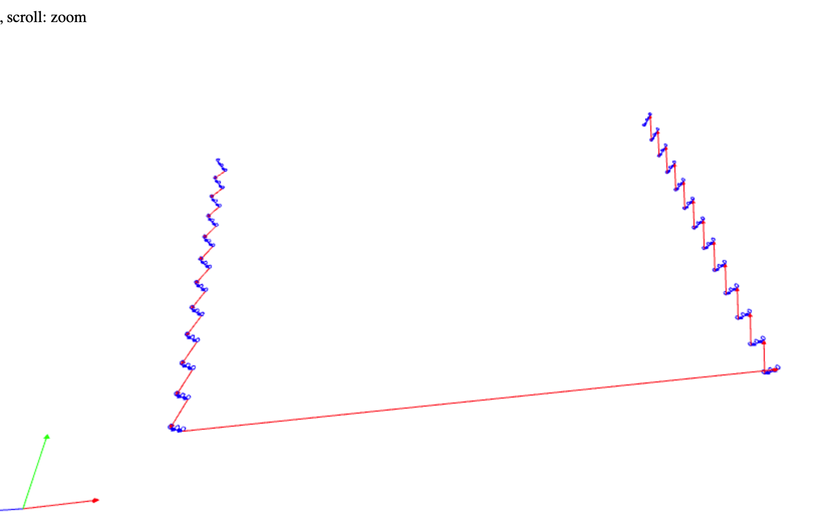
| import png file, set 1600dpi, select 1/64 mill | calculate, view tool path, output .rml file |
|---|---|
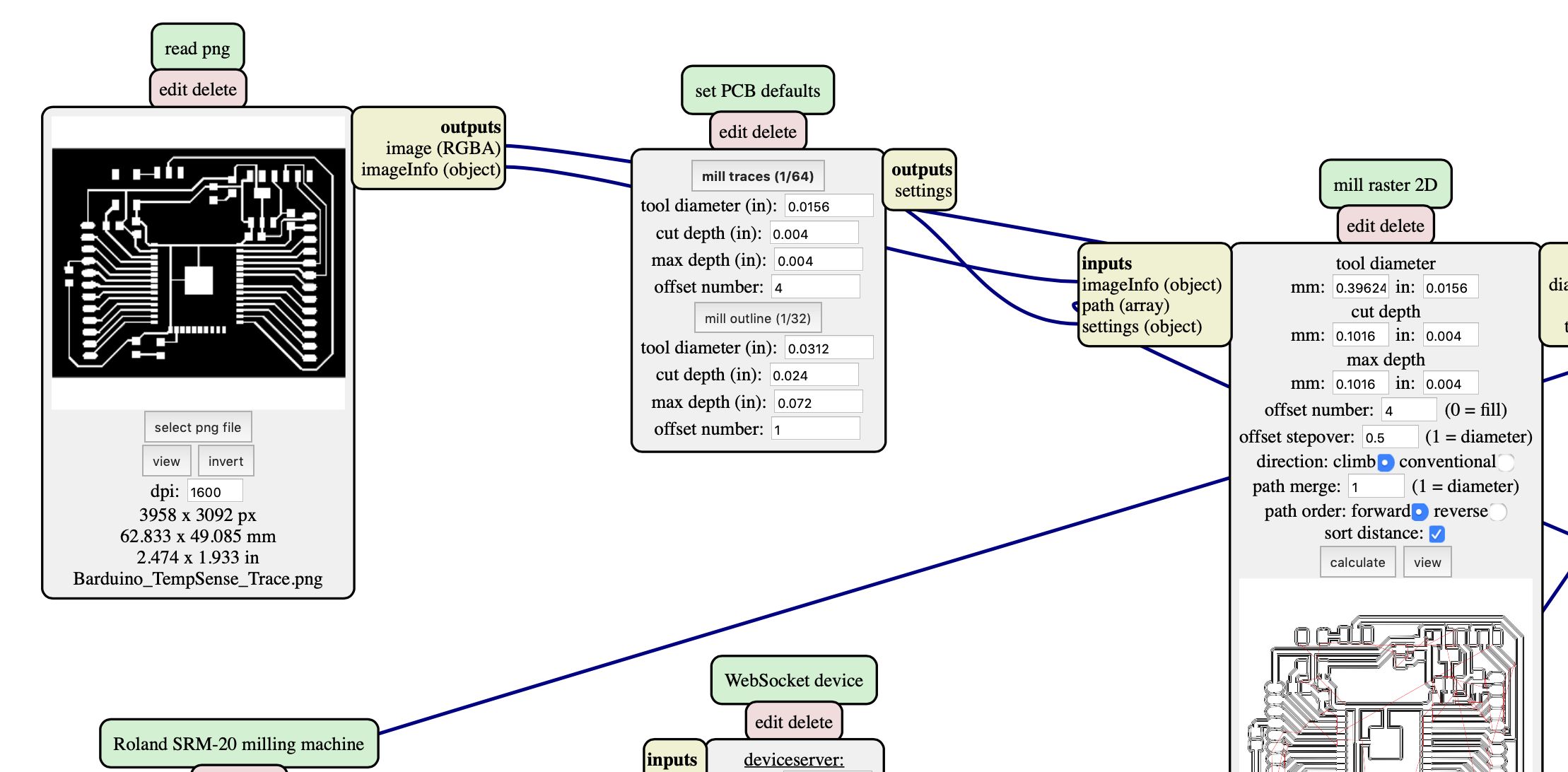 |
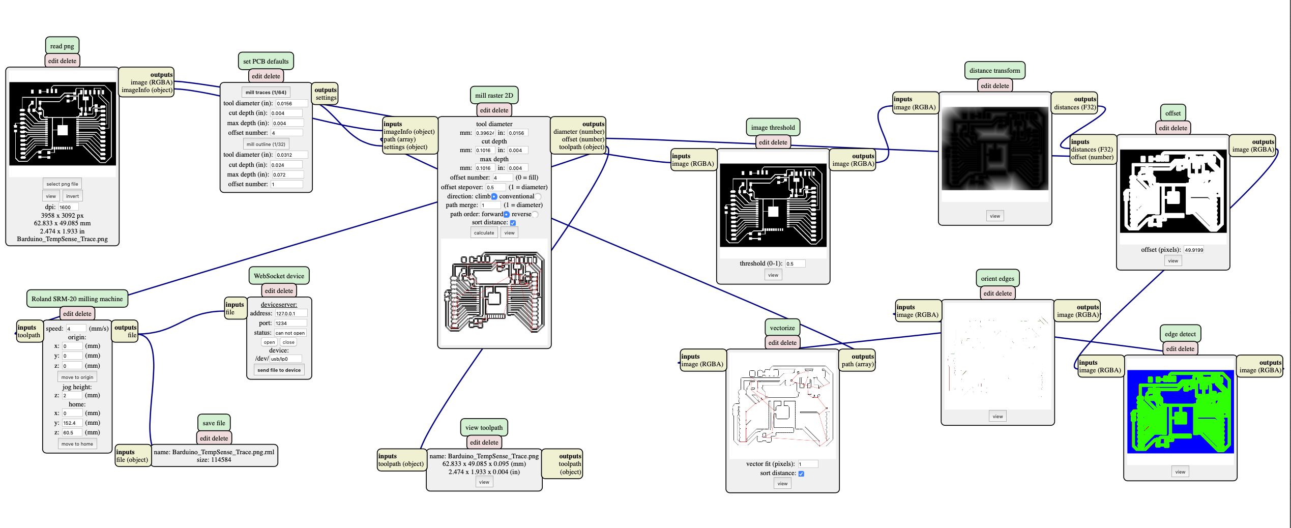 |
| tool path for “pattern” | drill holes |
|---|---|
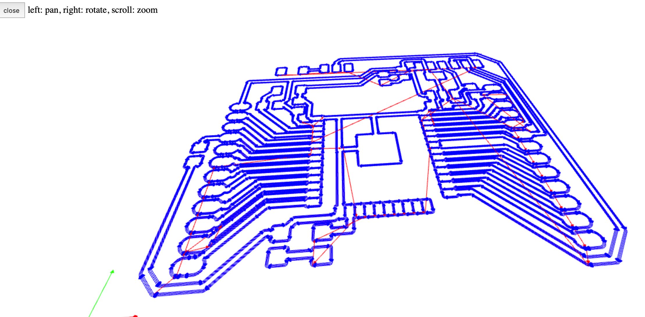 |
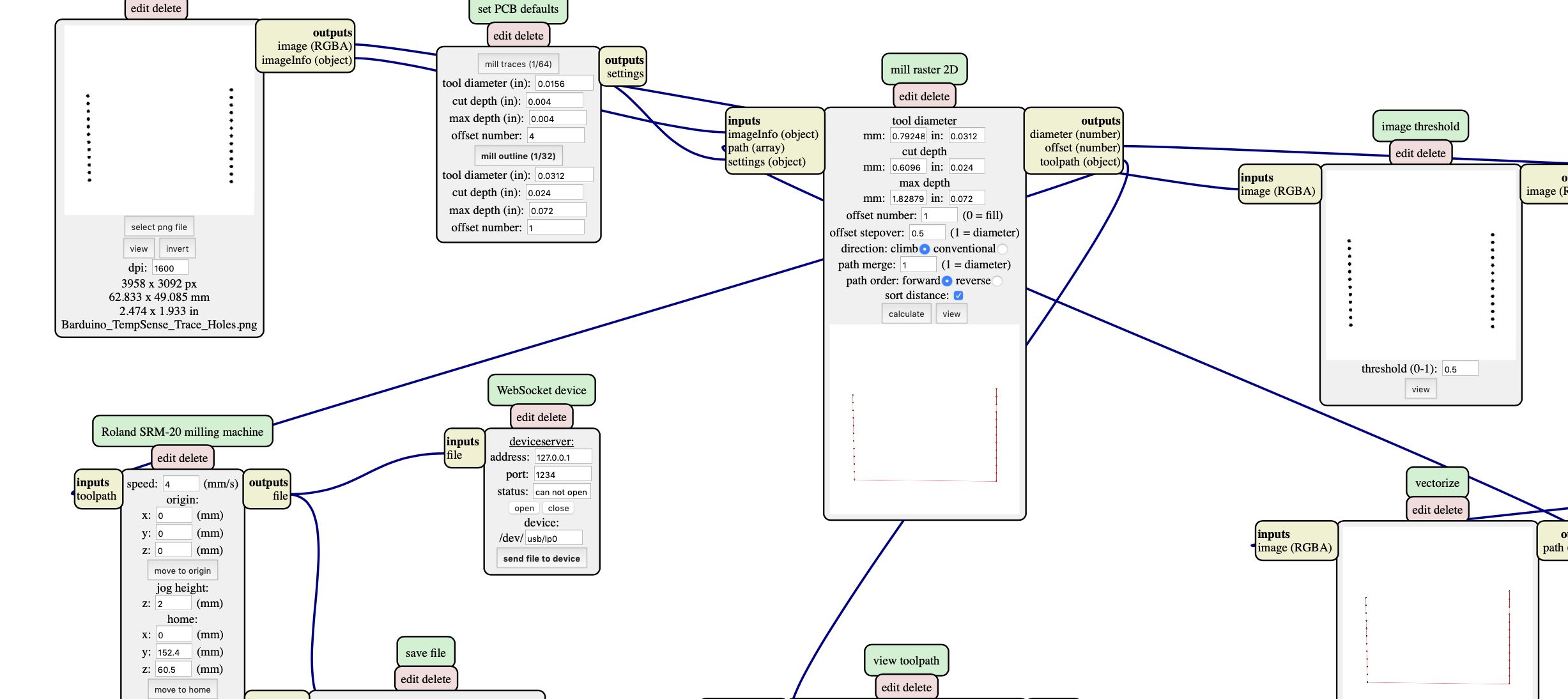 |
CNC parmeters for holes and outline
tool diameter (in) ; 0.0312 (1/32)
cut depth (in) ; 0.024
max depth (in) ; 0.072
offset number ; 1
milling speed ; 4 mm/s
| outcut | |
|---|---|
 |
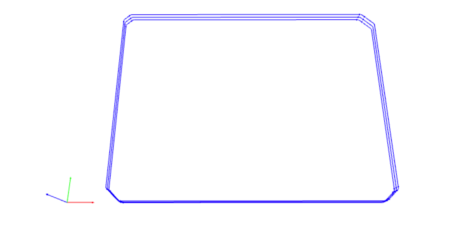 |
milling on SRM20
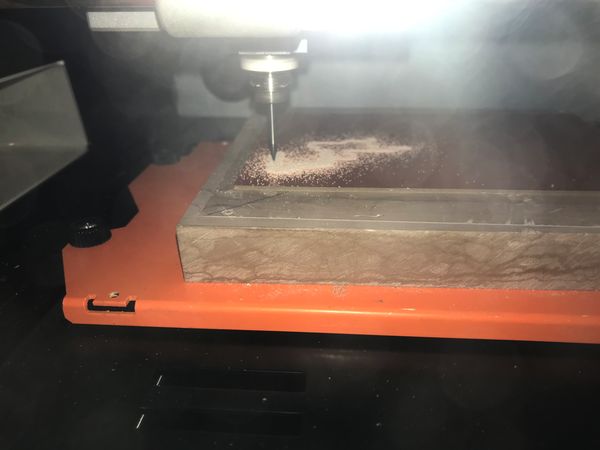 |
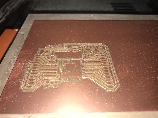 |
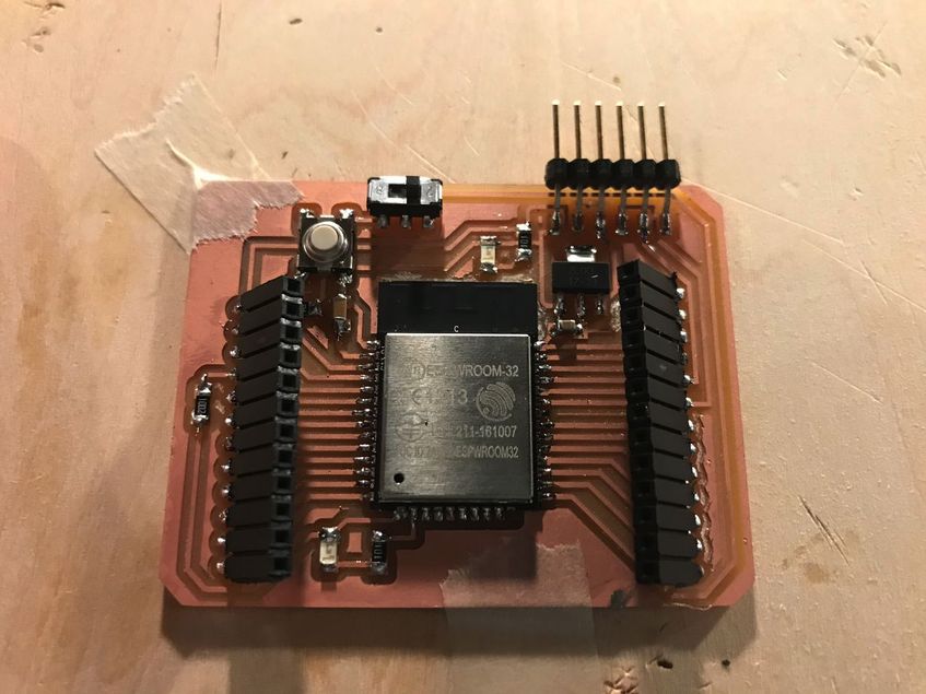
Actually, I missed the milling of the antenna portion, so I cut it manually using ultra sonic cutter.
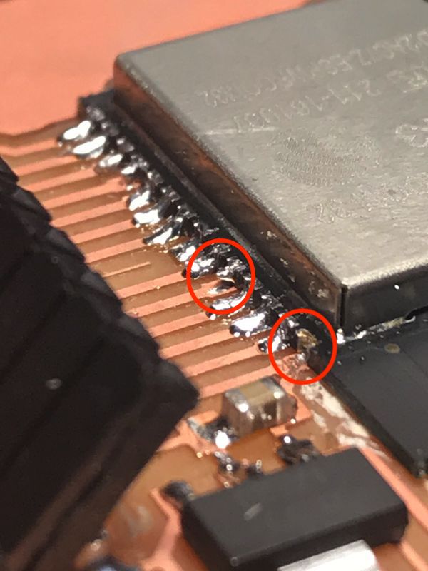
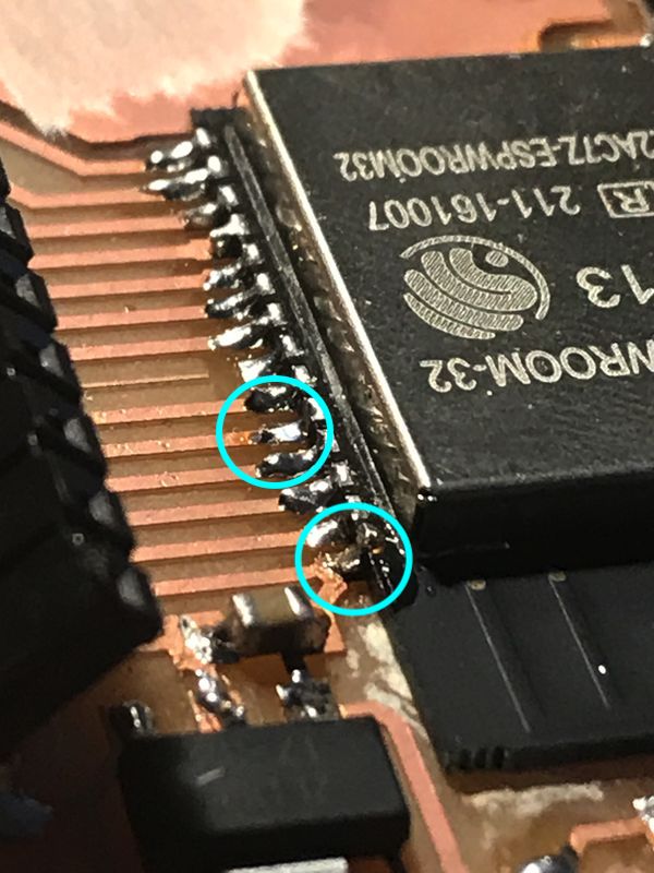
After stuffing the components, I found that GND and GPIO3 (RX0) are not soldered properly.
( That was because I could not find soldering flux. )
So, after I found soldering flux, modified the soldering. Then the functionality was OK.
| before | after |
|---|---|
 |
 |
 |
2-3) Packaging & Testing
To have the temperature value from NTC thermistor, I referred the site below.
temperature sensing with NTC thermistor
, then, modified some portion as follows.
(a) pin number
(b) measured voltage and resistance
(c) reading the temperature value via BLYNK BLE.
Regarding the setting of “Blynk BLE” on Arduino IDE and Blynk APP ( iPhone ), please refer ” 12. Interface and Application Programming , Group assignment Page “
“ESP32_Thermistor_BLYNK_BLE.ino”
#define BLYNK_PRINT Serial

#define BLYNK_USE_DIRECT_CONNECT

#include <BlynkSimpleEsp32_BLE.h>
#include <BLEDevice.h>
#include <BLEServer.h>

// You should get Auth Token in the Blynk App.
// Go to the Project Settings (nut icon).
char auth[] = "Your Auth Token";


#include <math.h>

int analog = 0;          //analog pin raw value
int V_0 = 3276;          //cirquit voltage [mV]
double V_R0 = 1;         //initial value of voltage devider[mV]
int circuit_R0 = 9800;  //resistance of voltage divider[ohm]

int thermo_B = 3380;     //B parameter of thermistor
int thermo_R0 = 10000;   //reference resistance of thermistor [ohm]
int thermo_T0 = 298;     //reference tempereture of thermistor[K]

double thermo_R = 1;     //initial resistance of thermistor[ohm]
double temp = 25.00;     //initial value of measured temperature[degC]

void setup () {

  Serial.println("Waiting for connections...");
  Blynk.setDeviceName("Blynk");
  Blynk.begin(auth);

  pinMode(34, INPUT);  // thermistor
  Serial.begin(9600);          /* 9600 bps connect serial */
  Serial.println("READ_START");

}

void loop () {

  Blynk.run();

  analog = analogRead(34);
  V_R0 = analog * 3.28 / 4096 * 1000;                 //voltage divider calculation
  thermo_R = V_0 / V_R0 * circuit_R0 - circuit_R0; //thermistor resistance calculation
  Serial.println( analog);
  Serial.println( V_R0);
  Serial.println( thermo_R);                 //printing thermistor resistance

  temp = (1000 / (1 / (0.001 * thermo_T0) + log(thermo_R / thermo_R0) * 1000 / thermo_B) - 273); //temparature calculation

  Blynk.virtualWrite(V0, temp);

  Serial.println(temp, 1);                                                     //printing temparature

  delay(100);                      // waiting for 0.1s
}
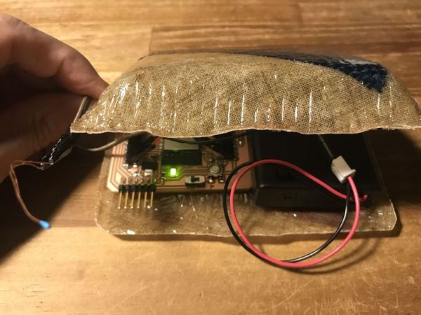
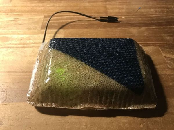
Setting the MCU and battery box into the composite case I made as the wildcard assignment.
 |
 |
Testing with warm water (about 50degC)
Although, more tuning ( calibration ) is needed, temperature from NPT thermistor is shown via BLYNK BLE.
4. Important Learning Outcome
1) I tried and understood basic characteristics of the sensors such as, “photo resistor”, “ultra-sonic distance sensor” and “thermistor”.
2) Through making PCB for thermistor I reviewed the workflow of EAGLE CAD and MODs, whose interfaces were a little complicated.
5. Links to Files and Code
Photo resistor ( CdS ) test
“Example06B.ino”
Ultra-sonic sensor test
“HC-SR04_test.ino”
Thermistor sensing PCB, EAGLE CAD
“BarDuino2.0_TempSense.brd”
“BarDuino2.0_TempSense.sch”
“Barduino_TempSense_Trace_rev2.png”
“Barduino_TempSense_Trace_Antenna.png”
“Barduino_TempSense_Holes_rev2.png”
“Barduino_TempSense_Outcut_rev2.png”
MODs
“Barduino_TempSense_Trace_rev2.png.rml”
“Barduino_TempSense_Holes_rev2.png.rml”
“Barduino_TempSense_Outcut_rev2.png.rml”
Thermistor sensing via BLYNK BLE
“ESP32_Thermistor_BLYNK_BLE.ino”
6. Appendix
CdS info “MI516”
“Making distance meter using Ultra-sonic sensor & Arduino”
HC-SR04
Thermistor
NXFT15XH103FA2B050 ( 10kOhm )
“resistor vs temperature” calculation link
Barduino (ESP32)