9. Input Devices#
Hall magnetic sensor (Oka)#
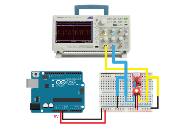
I researched hall magnetic sensor both analog one and digital one. They both could detect magnetic power but their outputs were different at all. I checked sensing values via arduino firstly, then I probed it by oscilloscope.
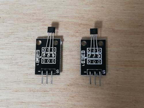
The left one is a digital sensor. The right one is an analog sensor.
analog sensor
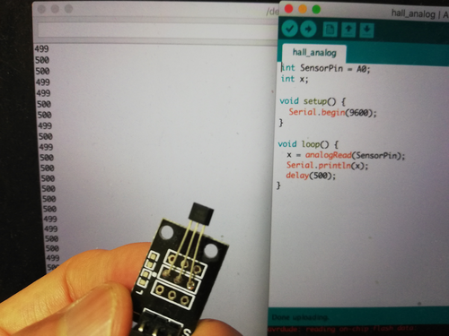
I checked the analog sensor firstly. Without magnet, the value was indicated around 500.
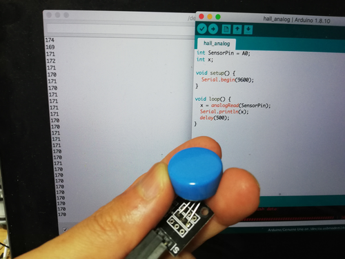
If the magnet got closer to sensor, the value was going down about 170.
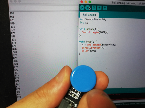
And, If I flip the magnet, the value went up about 880.
The value was always changing seamlessly depending on the length between the sensor and the magnet.
The voltage line existed in the middle. it meant around 3V was applied to the sensor without magnet. Then magnet getting closer to the sensor, the voltage went down to about 1V or less, and flipping the magnet led to the opposite consequence as the value going up around 5V. I could check visually the situation checked on the Arduino’s serial monitor.
digital sensor
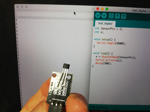
Secondly. I checked the digital sensor. It indicated 1 as default. I guess the circuit must be constructed by pull-up connection.
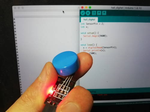
If I put a magnet near sensor, the value was changed to 0 and kept it after getting closer from the curtain point. And also LED was turned on at the same timing with the value turning to 0.
The line indicated over 4V stably at first. and it changed to 0V suddenly when I moved the magnet over the certain point to the sensor. And keeping away the magnet from the sensor, the line jumped to around 4V directly. It showed that the sensor give us output only two value.
these two sensors could detect the same substance well but the output were totally different. So we should carefully pick the one which has suitable character for what we are making.
Tsuchiyama#
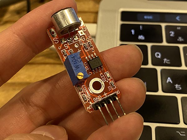
Sound Sensor (Sensor kit for Arduino)#
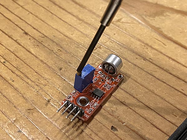
The sound sensor I used has a sensor module and a built-in potentiometer to adjust the sensitivity of the digital output terminals.
The layout of the pins is as follows.
| PIN | Wiring to Arduino |
|---|---|
| A0 | Analog pins |
| D0 | Digital pins |
| GND | GND |
| VCC | 5V |
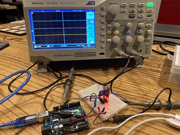
I connected the sound sensor breadboard to an oscilloscope and measured the output voltages of the Digital and Analog pins.
Schematic
↓
Blue waveform shows the voltage on analog pins and yellow waveform shows the voltage on digital pins.
Analog pins will output as HIGH when the voltage setting of the volume is greater than the analog setting. If not, they will be low.
If you want the digital pins to respond even at low volume, you need to lower the voltage setting of the analog pins in the program.
If digital pins do not respond during measurement#
There is an LED on the sensor module that indicates the digital output.
Turn the potentiometer to adjust the sensitivity of the digital output terminals and change the threshold level to find the point where the LED comes on frequently.
Oguri#
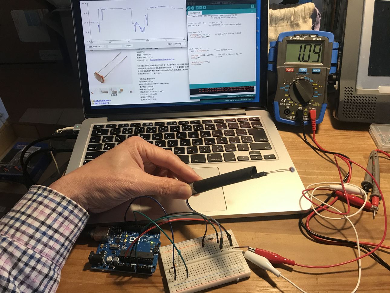
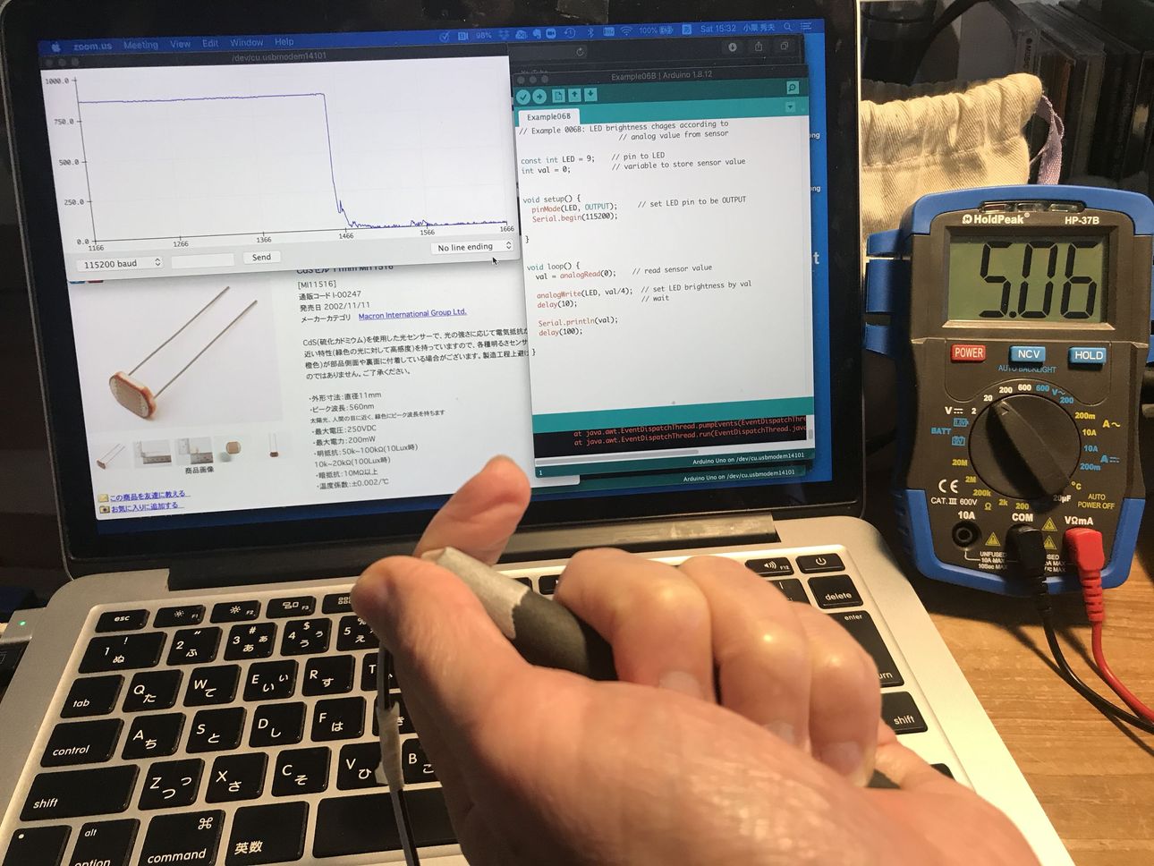
1) check the photoresistor ( CdS ) output by Arduino Serial Plotter, and control the LED brightness.#
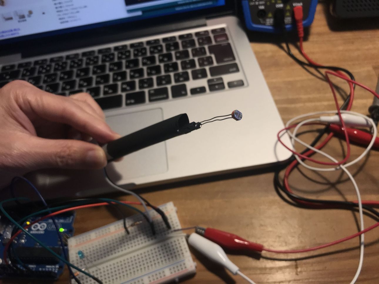
CdS info “MI516”
According to the datasheet, CdS resistance changes like below.
resistance ; 0.5 M ohm @ dark, 5 to 10 K ohm @ light (10Lux)
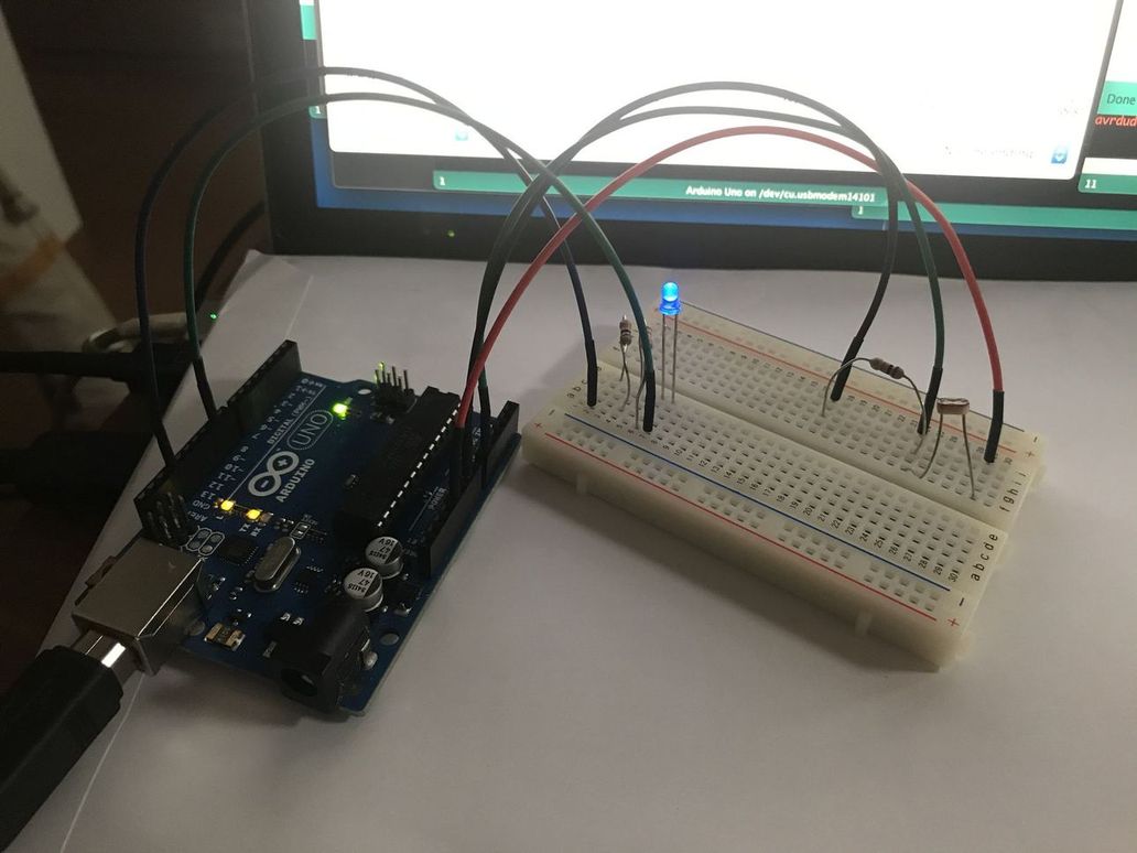
So, I connected CdS and Arduino UNO via 10k ohm voltage divider on breadboard ( 5v power supply was from USB of MacBook ).
then, observed the signal change on serial monitor on Arduino IDE.
“Example06B.ino”
( although LED was not needed for this test, I used the existing program. )
1 2 3 4 5 6 7 8 9 10 11 12 13 14 15 16 17 18 19 20 21 22 23 24 | |
 |
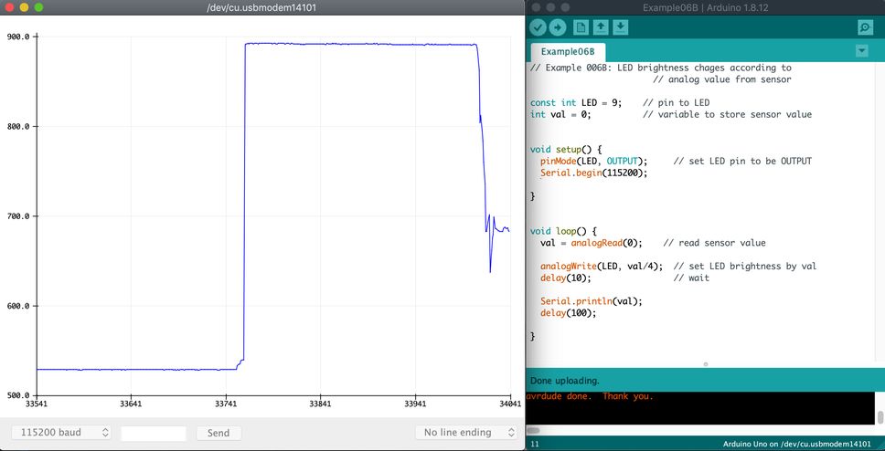 |
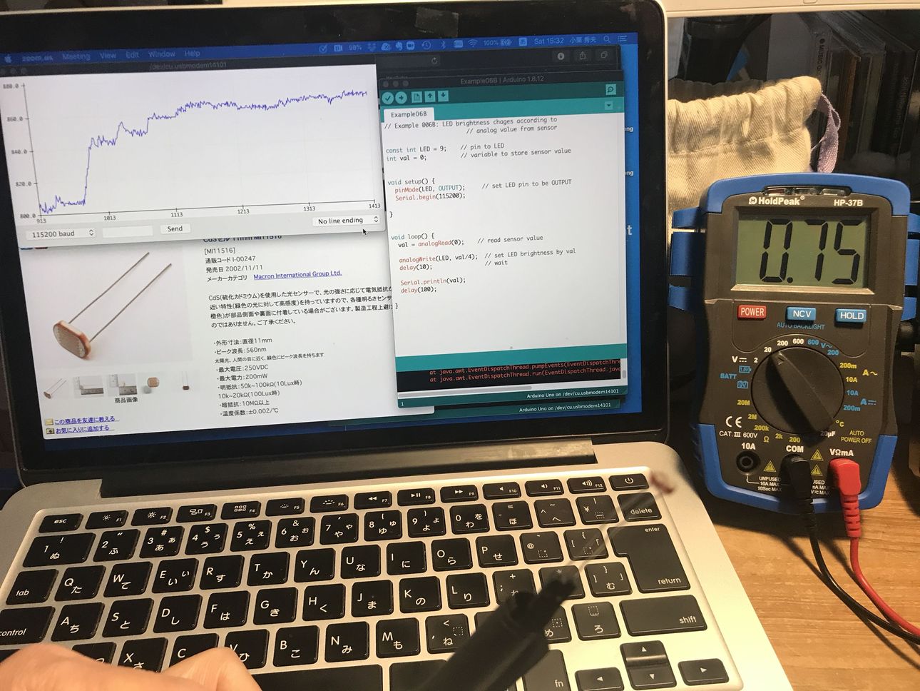
Then, I checked the CdS voltage.
 |
 |
| 0.75 V @ light (about 830 on serial monitor) | 5.06 V @ dark (about 0 on serial monitor) |
|---|---|
 |
 |
Although the Lux of light condition was unknown, considering the power source voltage (5 v) and resistance of voltage divider (10k ohm), the measured resistance of the CdS were as follows.
| data sheet | measured | ||
|---|---|---|---|
| Dark | Voltage | N/A | 5.06 V |
| Resistance | 0.5 M ohm | (infinity) (*1) | |
| Light | Voltage | N/A | 0.75 V |
| Resistance | 5 - 10 k ohm | 1.8 k ohm | |
| (10 Lux) | ( unknown) (*2) |
(*1) This was depending on the voltage measurement accuracy.
(*2) It is considered that the condition which seemed to be lighter than 10 Lux caused the resistance lower than 5 k ohm.
Yume#
Kimura#
Oscilloscope(echo hello-world board)#
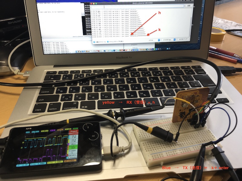
I apologize for the Japanese-speaking note, so I’ll add the explanation again in English.
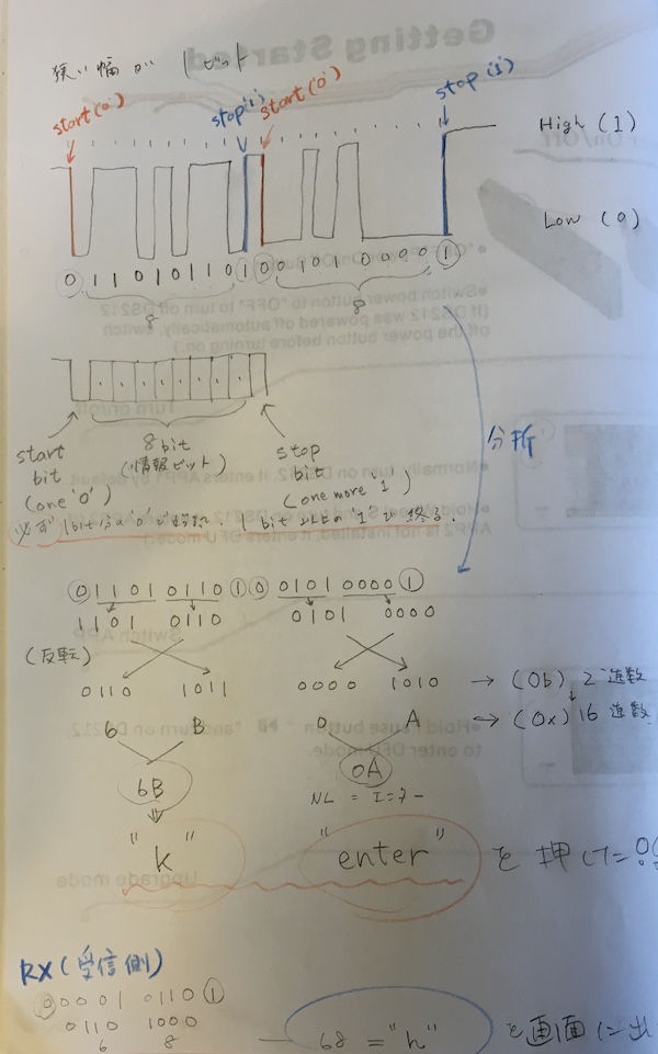
The narrow width is for one bit.
It starts at the start bit (Low), repeats 8 bits and Low, High, and then the end bit (High) sends the information of a single digital language.
It then divides the 8-bit information into four bits before and after, and converts the binary language into a hexadecimal number.
It then converts each of those bits into “6B” and “0A”.
If you check it in the ASCII code table, you’ll see
-
6B → k
-
0A → Line Feed(return)
It translates to.
Sure enough, I clicked on the keyboard with k enter.
I was impressed by what I thought was a little glimpse of language in the digital world.