W07 - Computer-Controlled Machining
1. Weekly Assignments ( -> what I did this week )
- Group assignment
test runout, alignment, speeds, feeds, and toolpaths for your machine
( -> During the cutting process, “feed rate” and “spindle speed” were adjusted, and observed the wood chips and machine noise. )
- Individual assignment
make (design+mill+assemble) something big
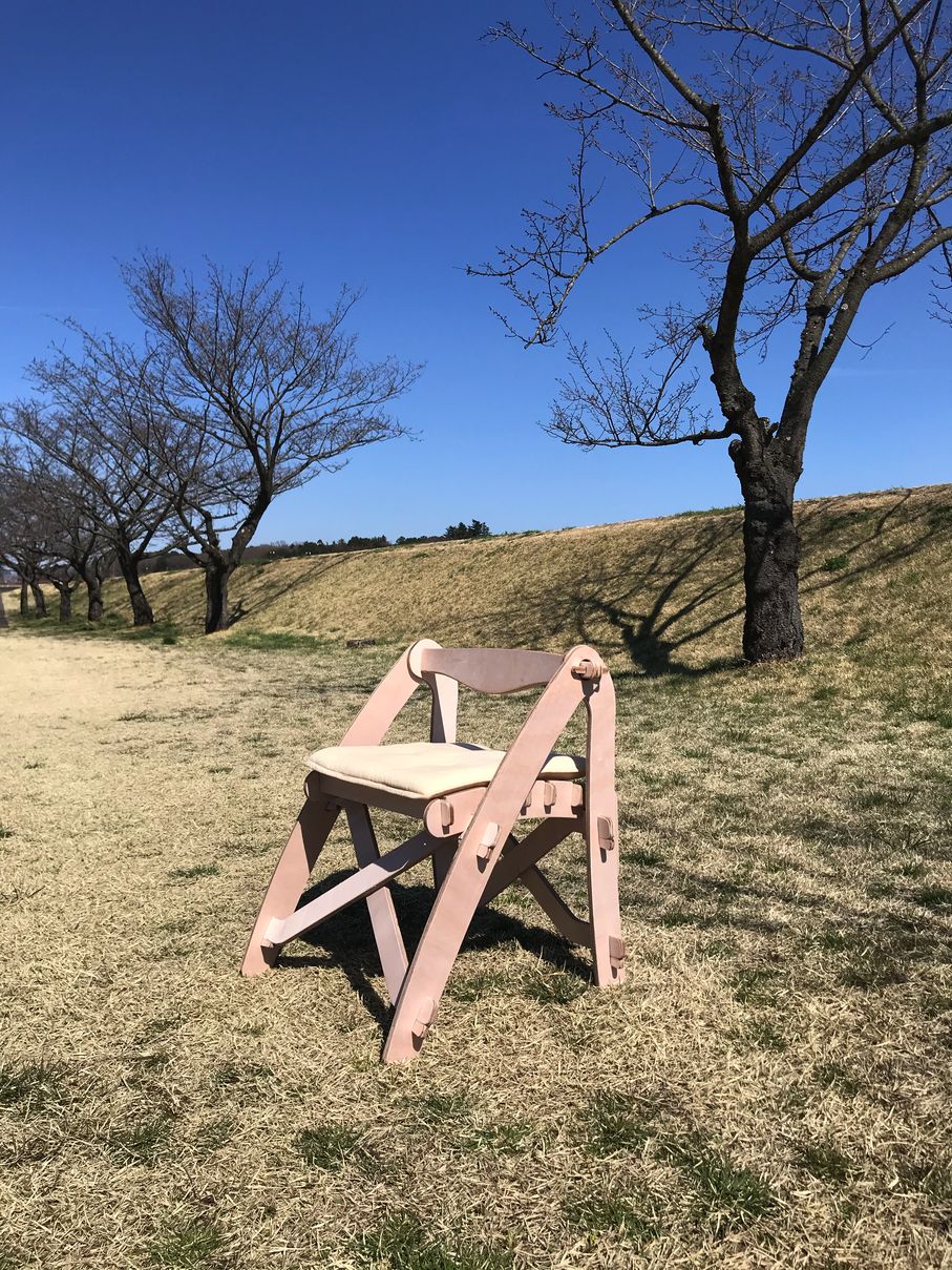
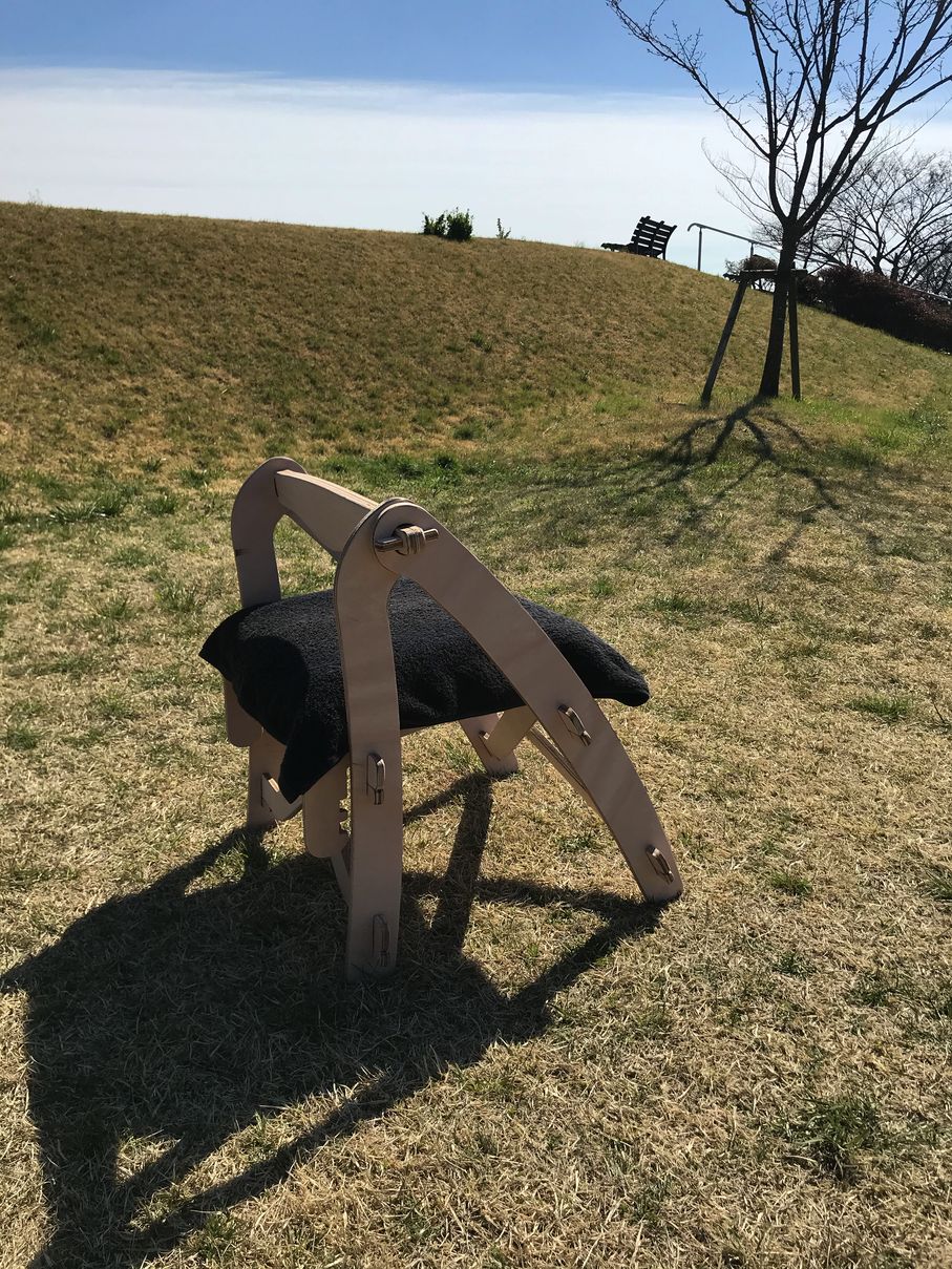
( -> I made a “folding chair”, cutting t12mm plywood (falcata) by CNC, which will be used for my Final Project. )
Have you?
Questions from “Fab Academy 2020 Assignments and Assessment 
( -> my answers )
-
Linked to the group assignment page ( -> yes )
-
Documented how you designed your object (something big) ( -> yes )
-
Documented how you made your CAM-toolpath ( -> yes )
-
Documented how you made something BIG (setting up the machine, using fixings, testing joints, adjusting feeds and speeds, depth of cut etc.) ( -> yes )
-
Described problems and how you fixed them ( -> yes )
-
Included your design files and ‘hero shot’ photos of final object ( -> yes )
2. Group Assignment Link
3. Works, steps and some details
1) modeling by fusion360
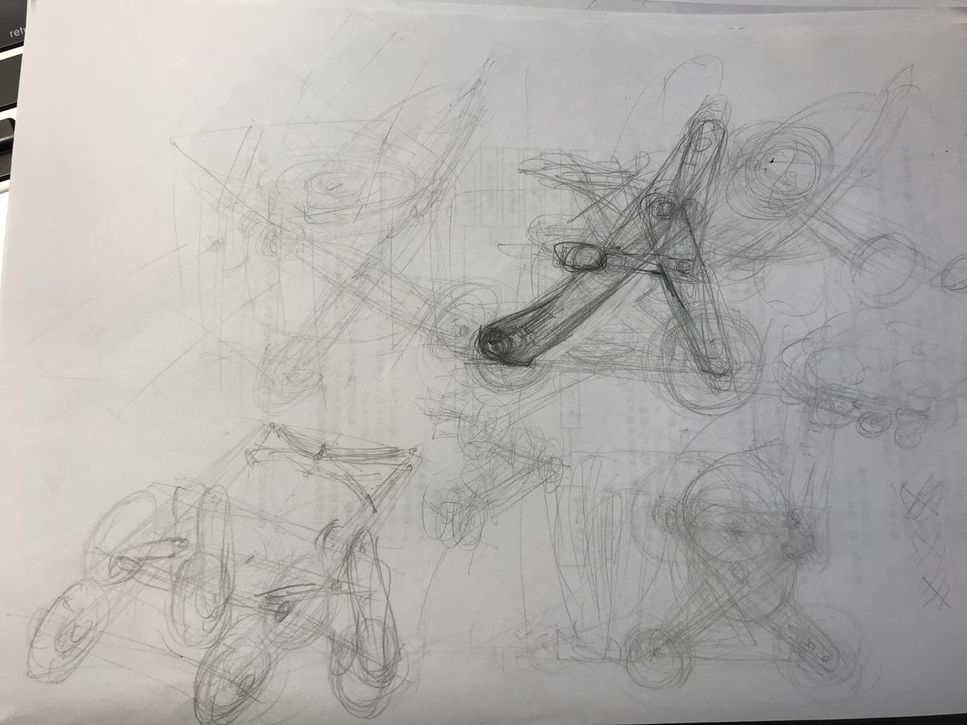
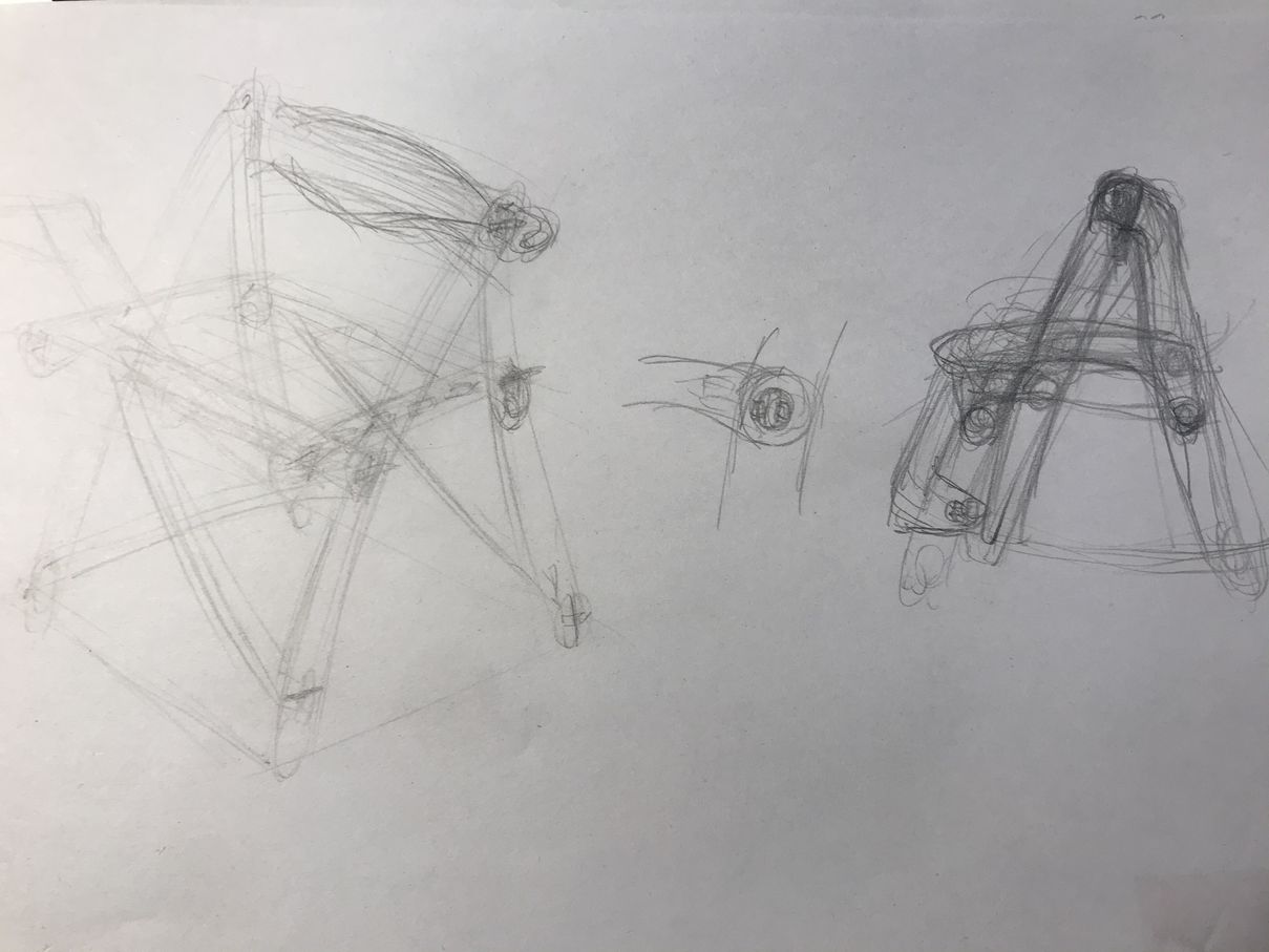
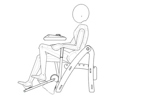
I decided to make a chair for my Final Project, considering the transportation, this should be folding type, and as light as possible.
| sketch (about 2 days before the CNC session ) | |
|---|---|
 |
 |
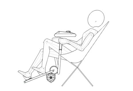
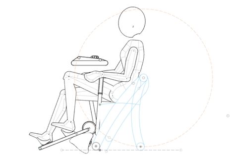
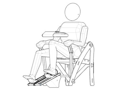
And, I changed the operator’s posture and the drive simulator position, so that he/she easily observe the drive simulator.
| before | after |
|---|---|
 |
 |
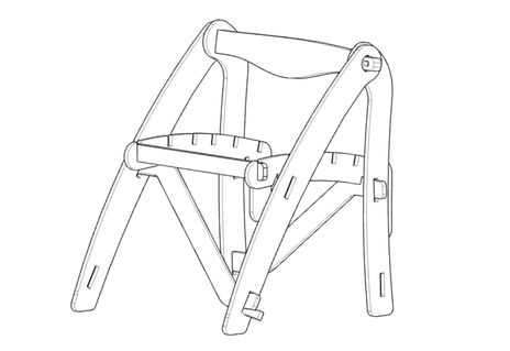
| modeling almost completed | |
|---|---|
 |
 |
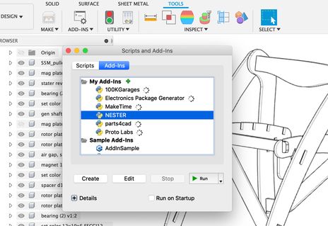
| completed | “NESTER” add-in was used to align the parts on one plane. |
|---|---|
 |
 |
Some components such as “stays” and “ribs” were not described in the model, to save time at the session.
Strictly speaking, all the components should be appeared in the model, but I omitted them because it was obvious that same components could be assembled repeatedly.
( “Open in Fusion360” button might not work on some browsers. To download the 3D model, please use the links in “5. Links to Files and Code” on the bottom of this page. )
I used “NESTER” add-in to align the parts on one plane.
fusion360 NESTER GitHub link video link
How to install sample Add-Ins and Scripts link
Then, converted to .dxf file
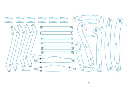
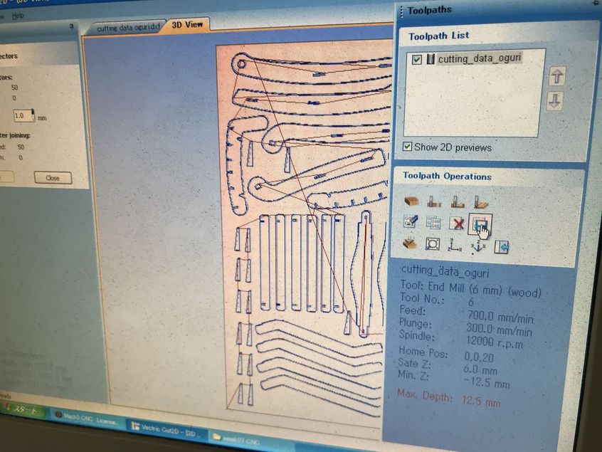
2) making CAM-toolpath
CAM-toolpath was made using “Cut2D”.
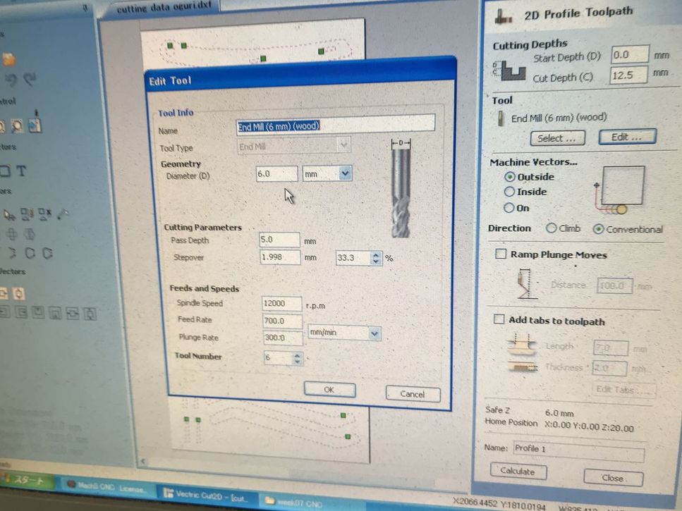
| open .dxf file from Cut2D | edit tool, mill diameter = 6mm ,etc. |
|---|---|
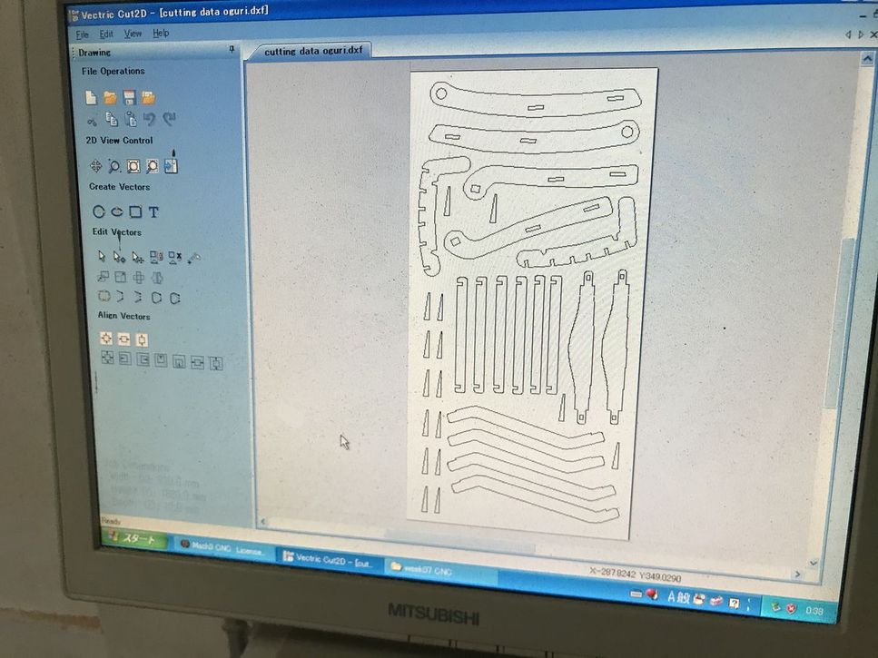 |
 |
| setting the “tabs” | tool path |
|---|---|
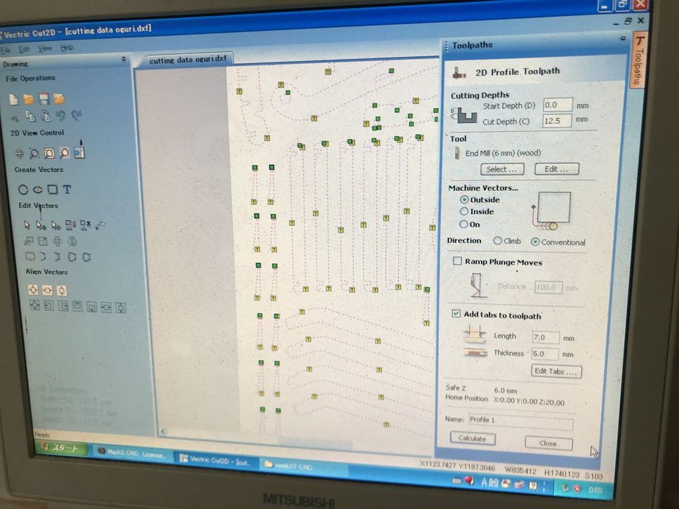 |
 |
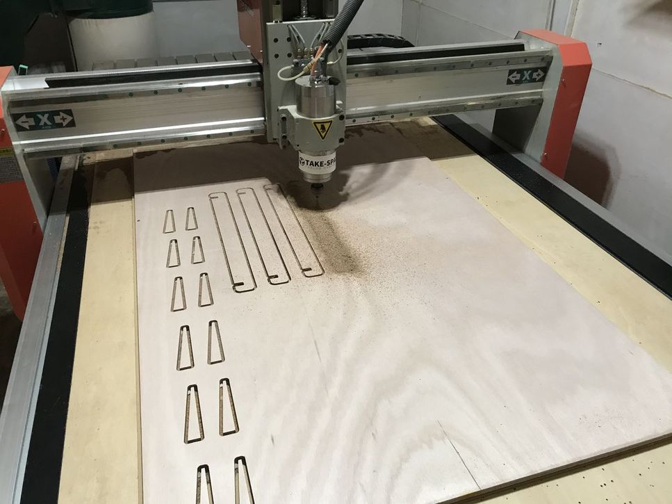
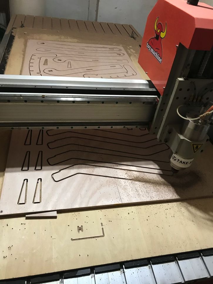
3) milling
material : falcata plywood 12 mm thickness
CNC router : ZN1325 at fablab Hamamatsu “Take-Space”)
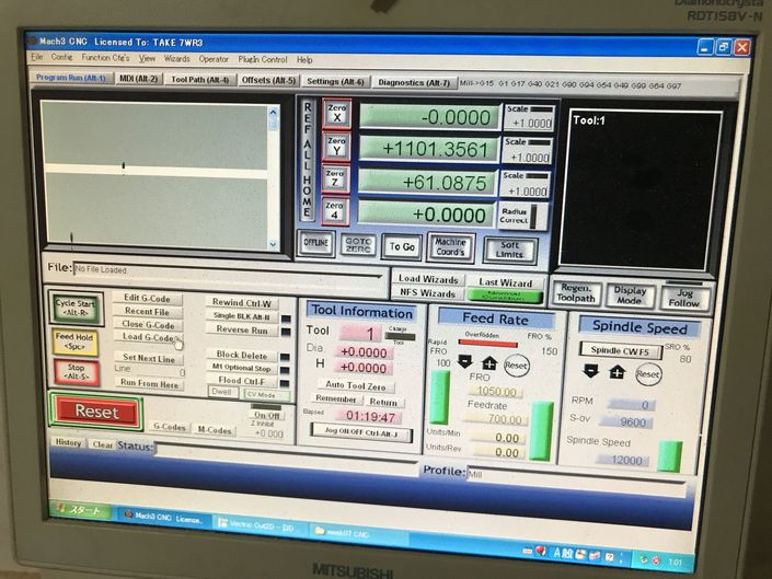
| setting “zero” (origin) for x-axis ( and then, y-axis also), after moving the mill to the corner of the wooden board. | mill position manual control from the key-board |
|---|---|
 |
 |
| “air path” to check the tool path | to perform “air path”, z-axis origin was set about 20mm above the wooden board. |
|---|---|
 |
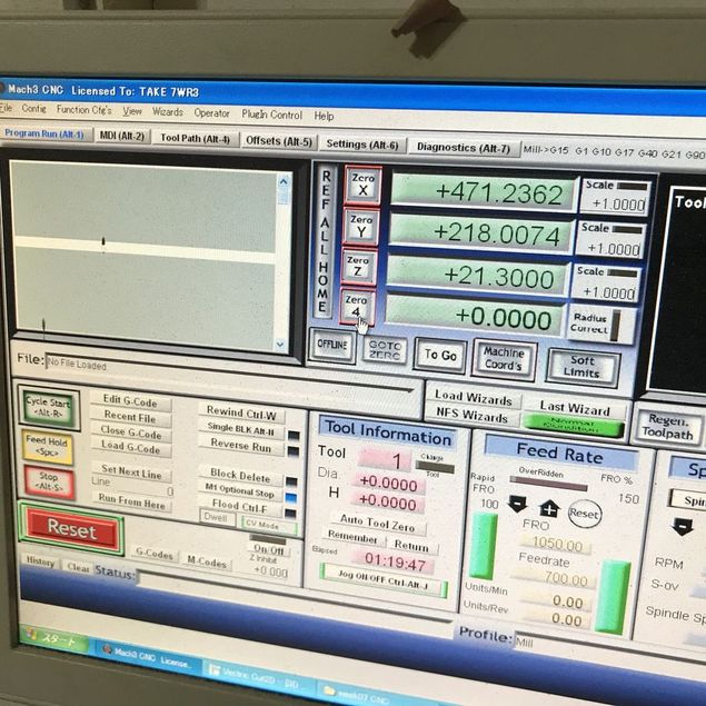 |
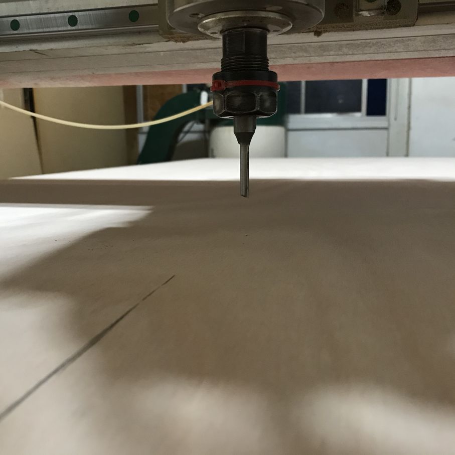
| to check the contact of the mill with wooden plate, paper was used. | setting “zero” for z-axis for milling |
|---|---|
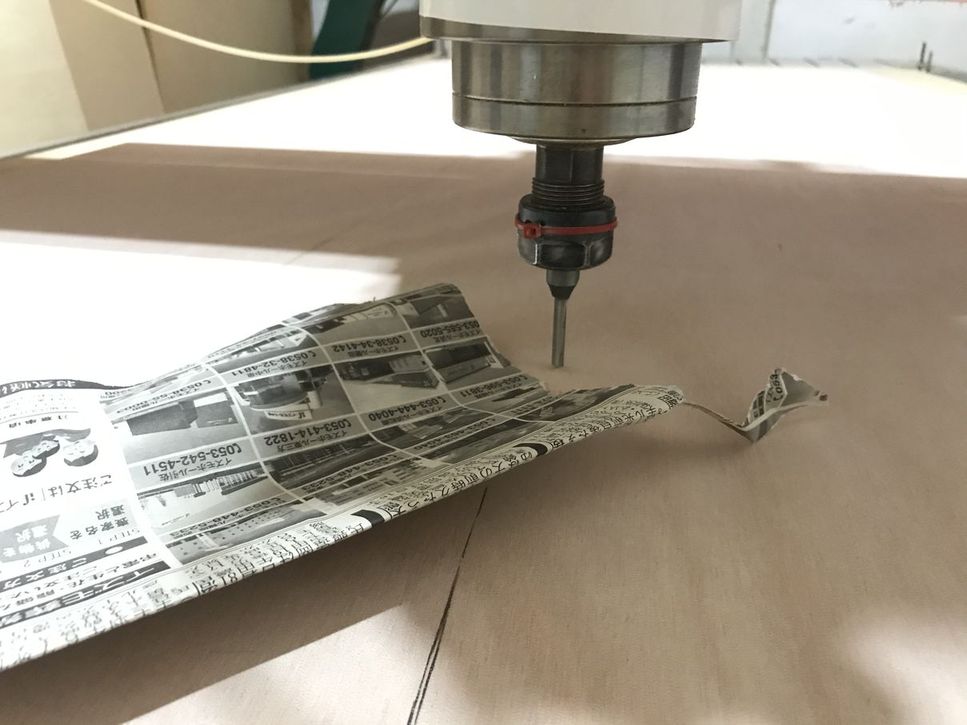 |
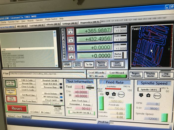 |
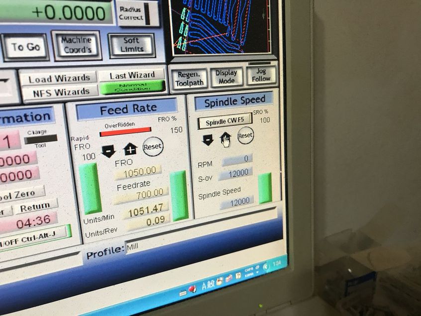
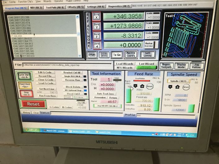
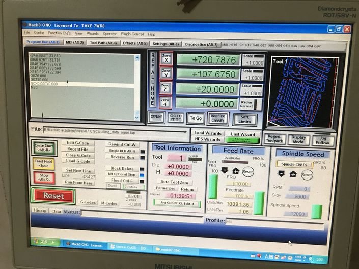
| start milling by pushing the “cycle start” button (left part of the window), feed rate :150%, spindle speed : 80% |
in this case,,, feed rate 100% = 700 rpm spindle speed 100% = 12000 rpm |
|---|---|
 |
 |
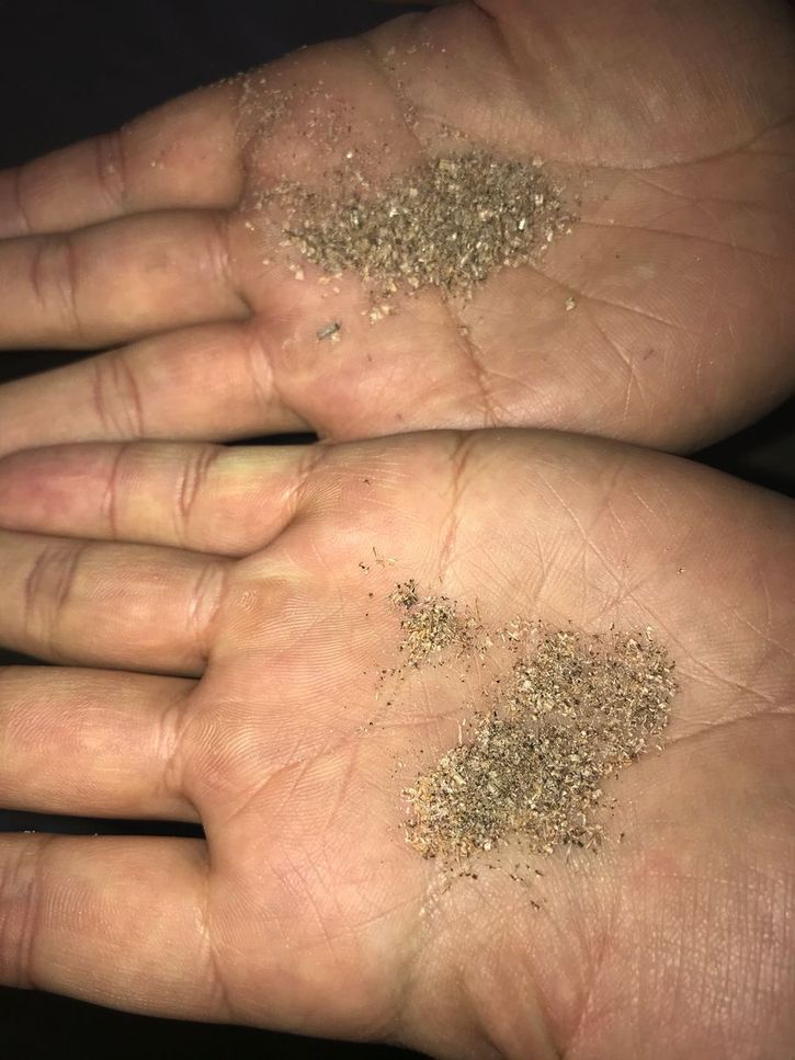
| parameter change feed rate :150%, spindle speed : 100% |
chips became a little finer (above ) |
|---|---|
 |
 |
| parameter change feed rate :130%, spindle speed : 100% then, machining noise was a little reduced. |
|
|---|---|
 |
 |
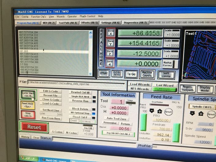
| total milling time was about 1 hour 40 minutes | |
|---|---|
 |
 |
4) assembling
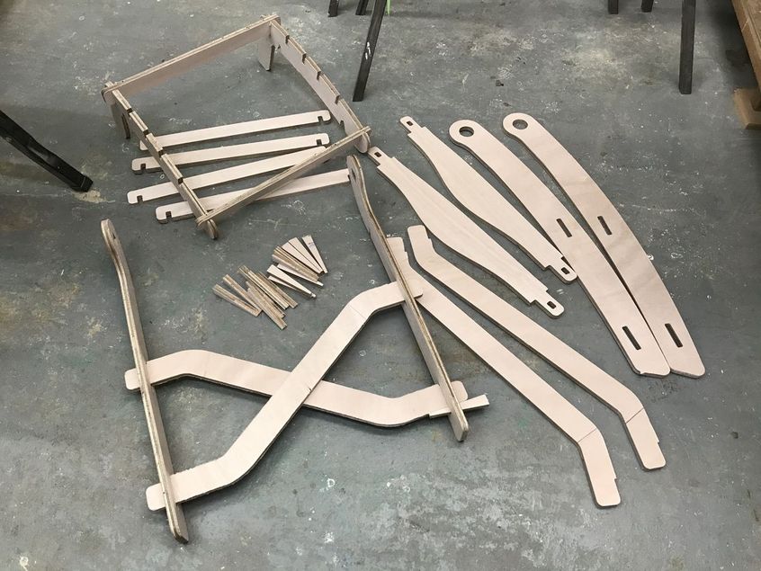
some connecting portions were modified/repaired by hand file.
| notch was added to avoid the element come off from the insertion | also, notch to hang the seat assembly when the seat is fold |
|---|---|
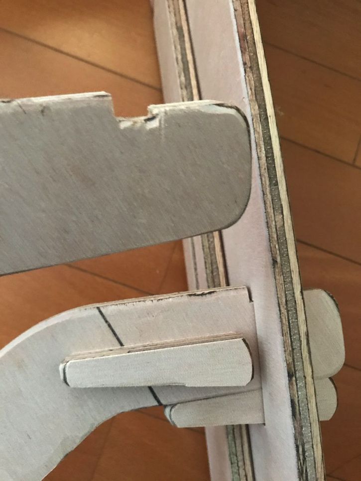 |
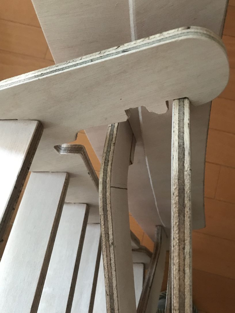 |
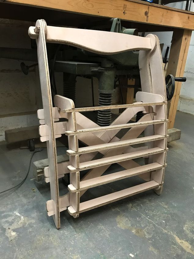
assembly work completed. ( it took about 7 hours. )
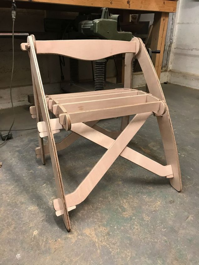 |
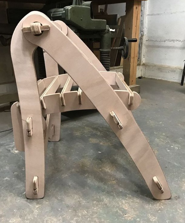 |
| folding condition | |
|---|---|
 |
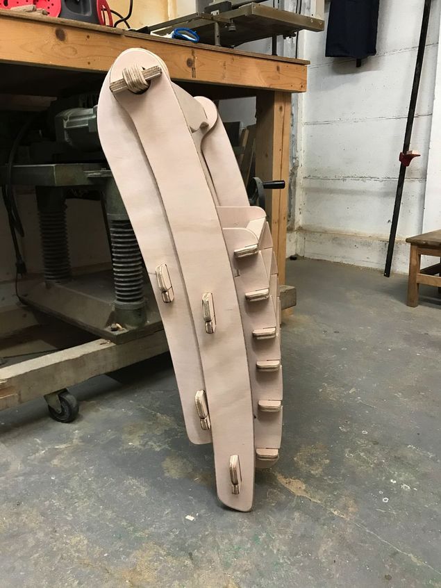 |
4. Important Learning Outcome
1) CNC workflow
- make 2D/3D CAD file
- make CAM-toopath ( by Cut2D, etc ), setting the tool (mill) information and “tabs” to support the material
- fix the material (wooden plate) on the bed of CNC
- set x-y origin at the corner of the material ( or any other appropriate position ), and set z-origin about 20 mm above the material surface, then, perform “air path” to check the tool path on CNC.
- set z-origin on the material surface ( by using paper to check the contact between tool tip and the material )
- start milling ( be prepared to push the stop button, in case of emergency )
- during the milling, check the wooden chips and the noise, then control the parameters such as feed rate, spindle speed, etc.
- after the milling completed, clean the material surface ( after moving the tool to the safe place, then “Jog OFF” )
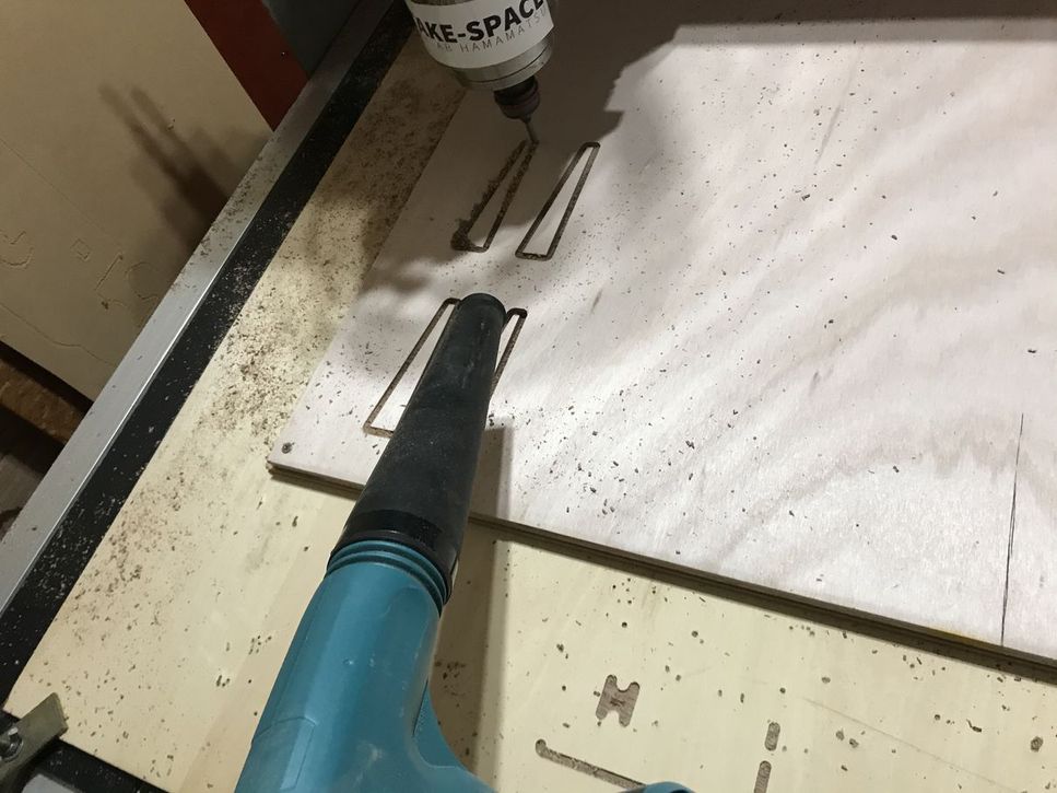
- cut the “tabs”, pick up the parts.
- remove the material and sacrifice plate, then clean the CNC and room.
2) about CNC
- Thanks to the accurate cutting ( milling ) work done by CNC, my chair was nicely assembled.
- Most of the 7 hour assemble time was spent to adjust the joint portions. If I could prepare the parametric 3D model, and could perform enough test cutting for them, it would be assembled more smoothly.
3) further plan
- 3D model improvement by implementing the necessary modifications which were found during the assembly work
- add the table function to support the drive simulator for my Final Project,
5. Links to Files and Code
folding chair
- fusion360 3D model : download
- .dxf file : “cutting-data-oguri.dxf” download
- .crv file ( Cut2D) : “cutting data oguri.crv” download
6. Appendix
fusion360 NESTER GitHub link https://youtu.be/KCEwoHBlh5Y
How to install sample Add-Ins and Scripts link
Cut2D link
MACH3 manual “Using Mach3Mill” link