3. Computer Aided design and modeling
Due date 2024/02/06
How to use this document
Please refer to instructions in the week02 weblog entry
Conceive
This week we familiarize ourselves with several modeling and computer-aid design (CAD) tools used to represent two- and three-dimensional objects. The skills that I gained this week will help me visualize and test ideas. CAD is like sculpting with a computer instead of a chisel and mallot.
Assignments
| Have you? | Done |
|---|---|
| Group assignment: | ⬇ |
| None | NA |
| Individual assignment: | ⬇ |
| Model: | |
| Raster | Yes |
| Vector | Yes |
| CAD | Yes |
| Render | Yes |
| Animate | Yes |
| Simulate | Yes |
Learning outcomes
| Have you? | Done |
|---|---|
| Evaluate and select 2D and 3D software | Yes |
| Demonstrate and describe processes used in modelling with 2D and 3D software | Yes |
Checklist questions
| Have you? | Done |
|---|---|
| Modelled experimental objects/part of a possible project in 2D and 3D software? | Yes |
| Shown how you did it with words/images/screenshots? | Yes |
| Included your original design files? | Yes |
Context
- Syllabus FAW03
- Assessment FAW03
- Tutorial FAW03
- Video FAW03
- Review FAW03
- FabAcademy 2021 Documents
- FabAcademy Evaluation Page This site requires a fablab.io account to login
- FabAcademy Home Page
- FabLabs Home Page
Comprehend
- One performs CAD with software that constrains drawings to real-world parameters such as machining considerations in order to improve manufacturability. Modern design software should produce data that describes the physical characteristics of idea. TMEH v.5, ch.16-4
- Autodesk Fusion 360
- Form (durability, rigidity, stability)
- Cloud-based
- Continuous integration of software improvements
- Supports several modeling types
- Direct
- Surface
- Parametric
- Mesh
- Freeform
- Collaboration tools are built-in.
- Provides features such as electronic design
- Includes simulation
- Includes manufacturing support
- Function (efficiency, reliability, accuracy)
- generative design makes it more efficient to vary a design
- Integrates version control of designs
- Simulation makes it possible to test a design before manufacturing
- Integrated manufacturing processess means the designer can perform design for manufacturing on along with CAD on one platform
- Rendering in the cloud means designs finish up to 75% faster than they would if rendered locally.
- Form (durability, rigidity, stability)
Individual assignment
Take caution
- Not applicable
Calibrate
- Not applicable
Control
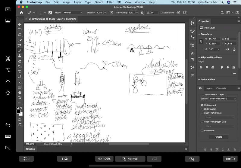
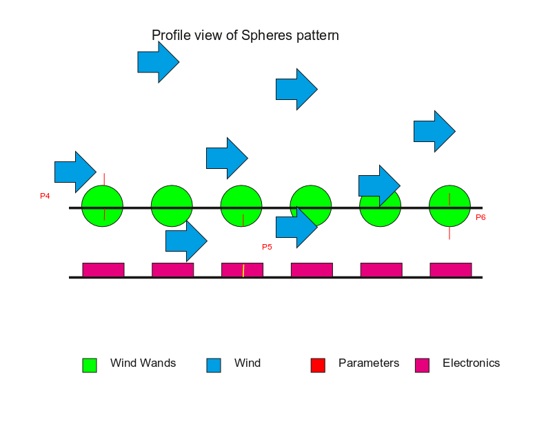
- Human-visualization of idea interface
- *This video illustrates the inspiration for the Nfr Wind Wand idea
- A sketch of the idea.
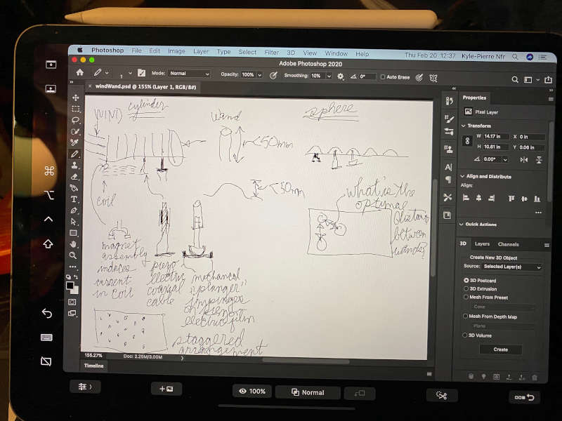
Raster
- 2-dimensions: Raster Adobe PhotoShop
 Return to assignments
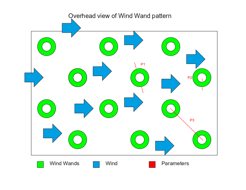
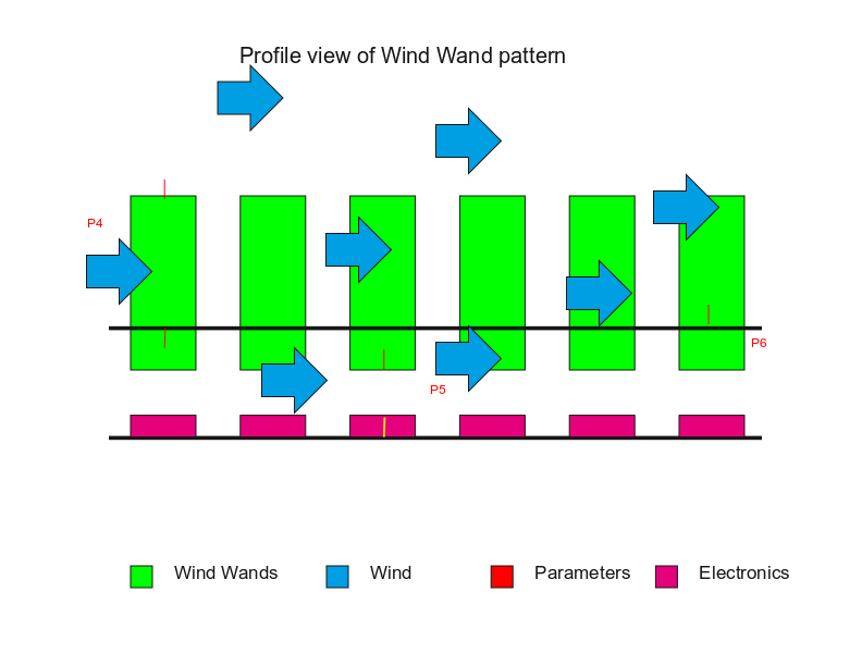
Vector
- 2-dimensions: Vector Scribus (Open source)
 Return to assignments
CAD
-
Idea-CAD interface
- Create a team if necessary.
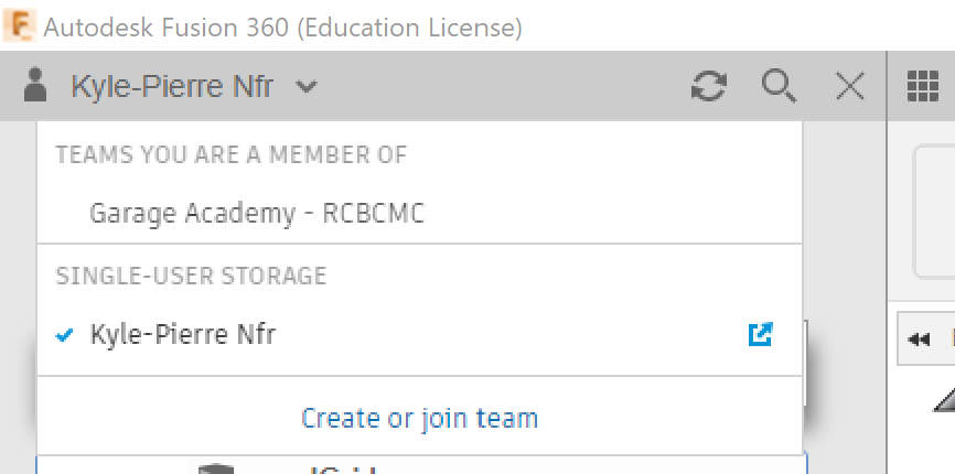
- Create at least one project folder under that team.
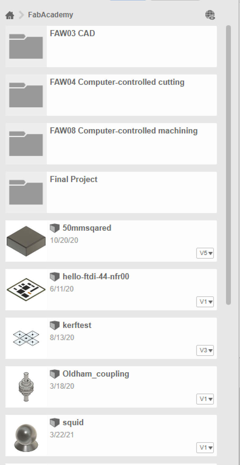
- store all parts for the project in that folder
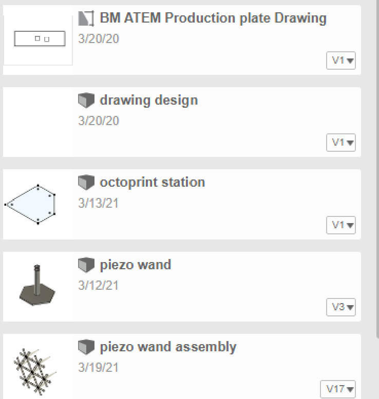
- Create at least one project folder under that team.
- Create a team if necessary.
-
CAD-design interface
- Best practice: Start a new design in an empty document.
- Best practice: Set its default units
- Best practice: Save the document.
- Best practice: Create a Base Feature for the design.
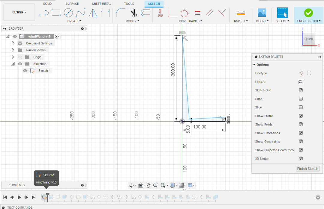
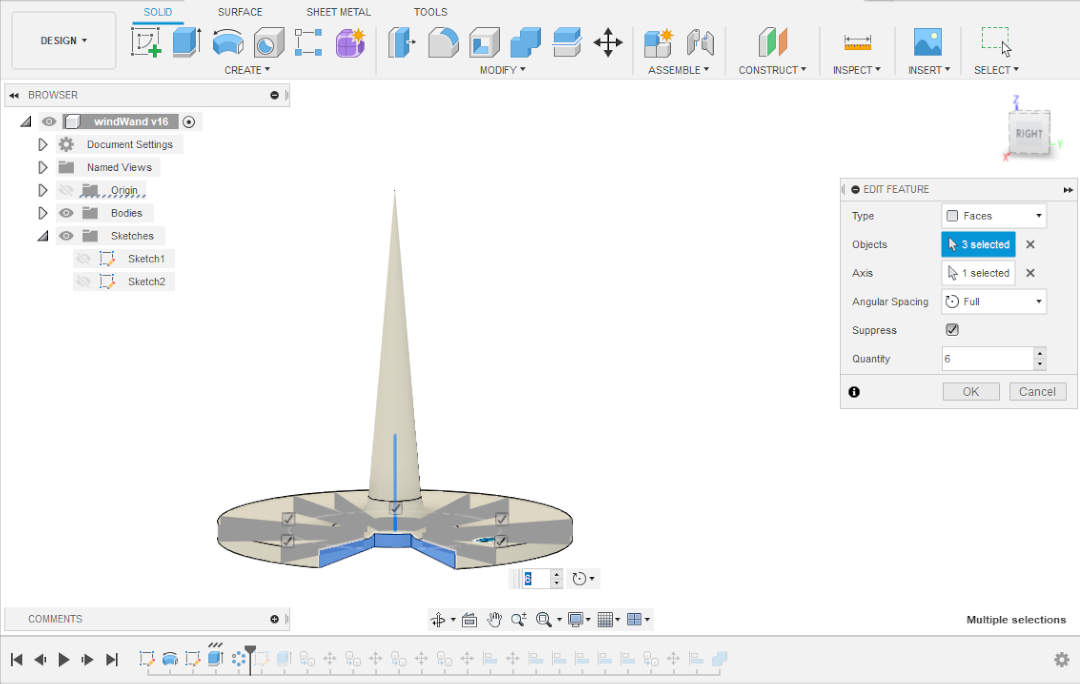
- Best practice: Pretend that the design is hiding in lump of material with a 2-dimensional profile constructed from primitive shapes: circles, rectangles, triangles, and lines. Sketch the profile using these primatives. Extrude the the profile. Then, modify the extrusion by removing or adding material to the part in order to more closely create the final design. *Base Feature steps will not be recorded in the timeline.
- Sketch a profile of the first feature
- Constrain it. Sketch elements remain under constrained–represented by their blue color–until they turn black.
*The profile pictured below was left intentionally under constrained.
- Extrude or Revolve the profile.
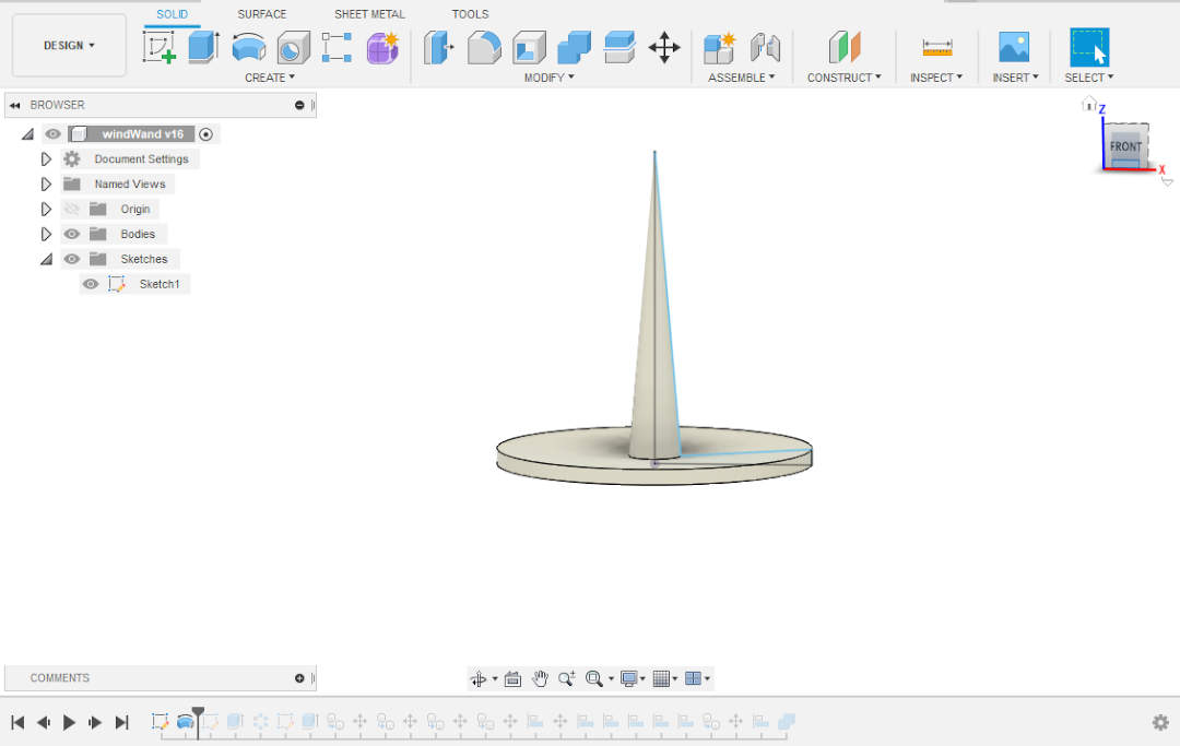
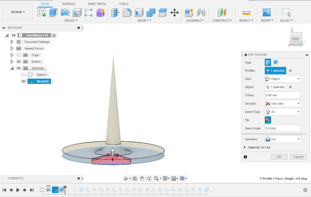
- Modify the Body by adding Features to it.
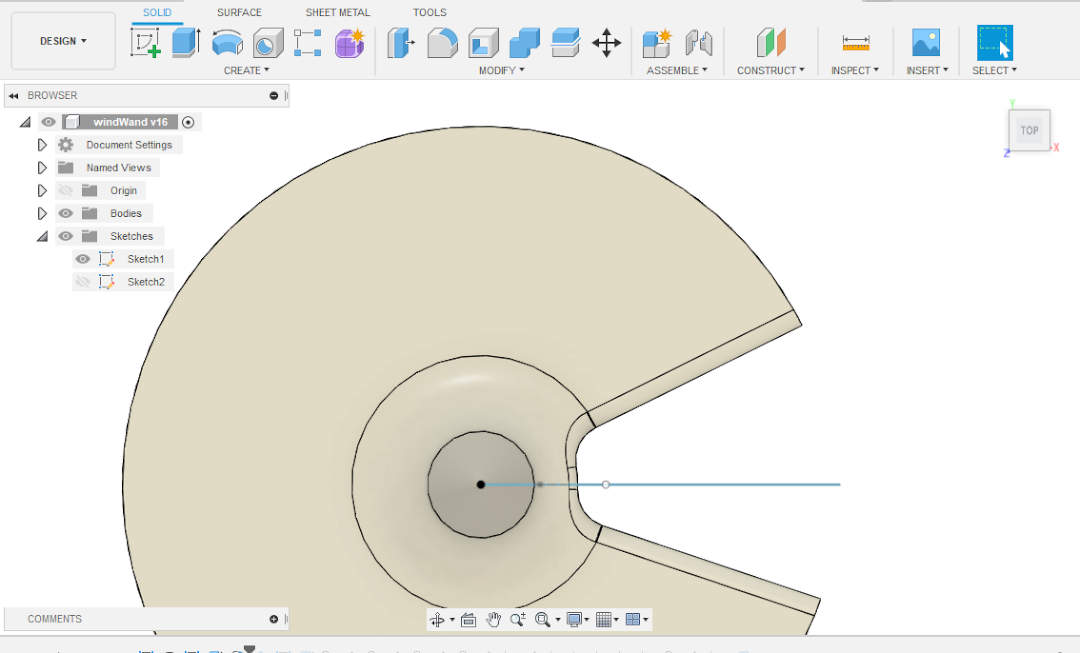
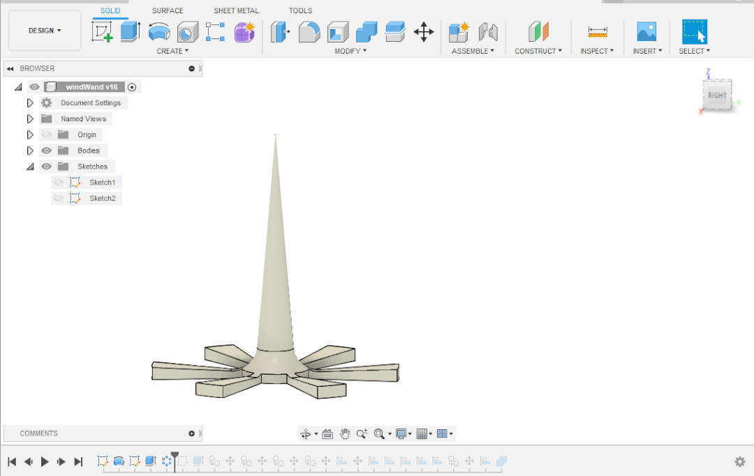
- Repeat steps 5-8 for every Body that you need to create a part.
- If necessary, Combine the Bodies into one part. This will make finite-element analysis much easier and more accurate.
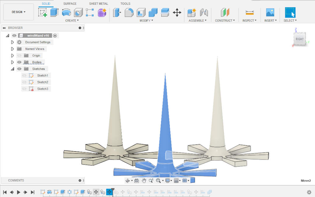
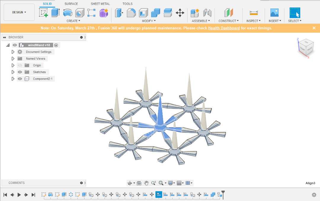
- parts that will be Assembled by Joints with one another must be converted to Components from Bodies.
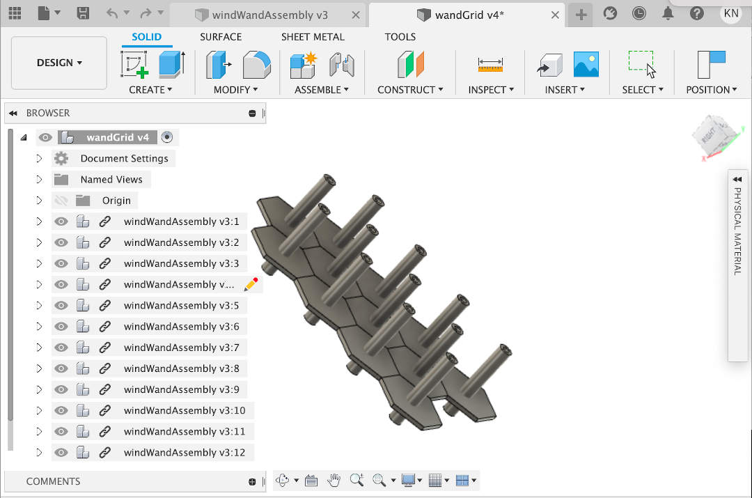 *This Assembly would not Simulate correctly because the parts were converted to Components then Joined and they interferred with one another.
Return to assignments
*This Assembly would not Simulate correctly because the parts were converted to Components then Joined and they interferred with one another.
Return to assignments
Animation
- Design-animation interface
Simulation
- Design-simulation interface
Render
- Design-rendering interface
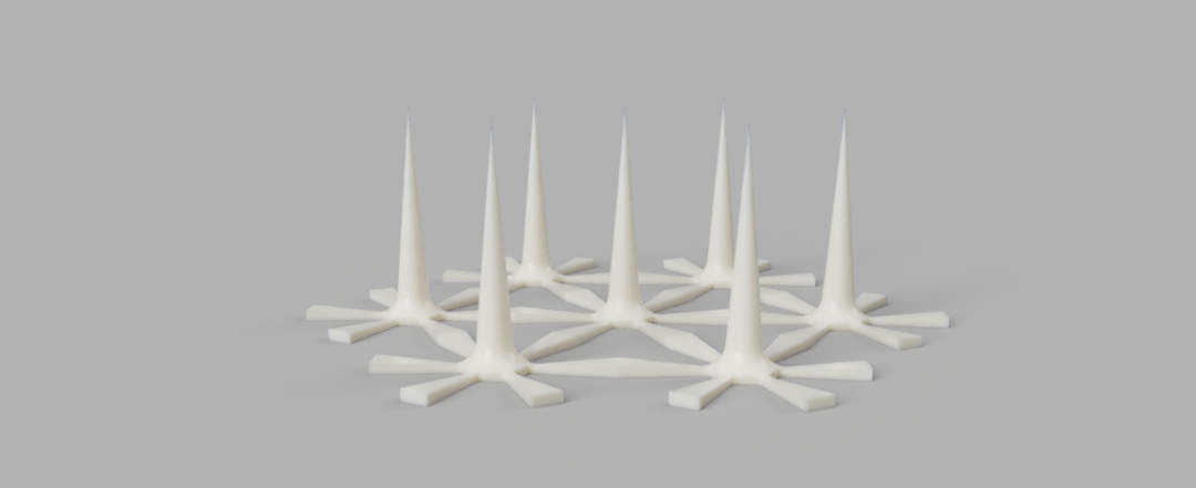 Return to assignments
Files
- CAD files from design Fusion windwand file, DXF windwand file
Tips, Tricks, & References
- Tool and Manufacturing Engineers Handbook, Volume 5
- Your First Design in Autodesk Inventor 2017
- Parametric Modeling with Autodesk Inventor R11
- Source for Fusion 360 product tutorials Home>Learn>Product tutorials>Fusion 360 and here
- The VLC program provides open-source video-format conversion Render Autodesk Fusion 360