5. Electronics production
This week has been quite fun! I had never tried a milling machine before nor soldering, so it was quite interesting to go through both of them.
We got a traning of the machine with our istructor and then I followed the training in the tutorials’ page.
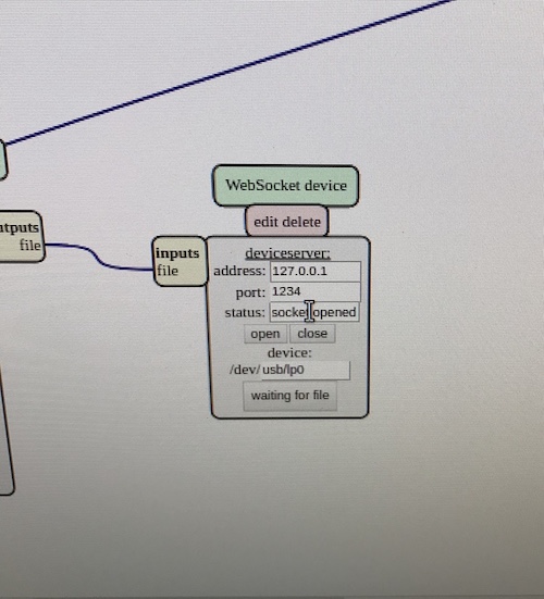
First of all, we need to start MODS. We go on programs and then ‘open server program’ and the select the machine we use. In our case, the machine is Roland SRM-20 milling machine. We were told that it is preferable to use Linux for MODS. In order to connect MODS to the machine, we need to make sure to click on the file ‘start mods server’ so that the machine is connected to the MODS and the in mods click on OPEN in the status bar to start the connection.
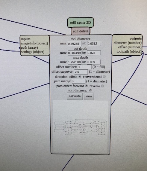
To do the milling, we need to start by loading the image by starting with the traces part (after it will be the turn of the outline). When clicking on mill traces, MODS will automatically load certain settings. We changed the settings slightly so that the cut depth and max depth are 0.006 instead of 0.004 in. A good rool of thumb is that the max depth should not be more than half the size of the tool diameter.
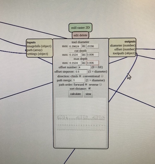
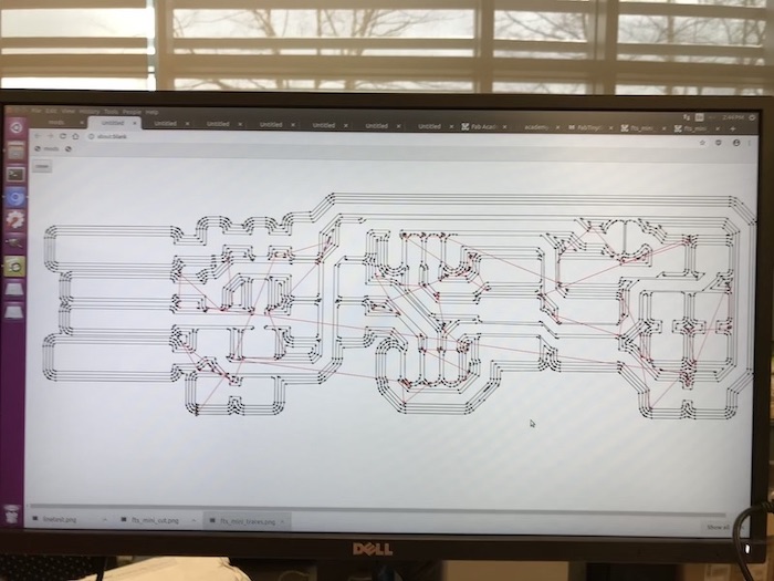
Cut depth is the depth of the machine in each turn and max depth is the maximum depth the milling to get to. In this case, the machine will cut only one layer of 0.006 inches to make the engraving. The other settings which are important are ‘offset number’ (which is the number of lines the machine will make) and ‘offset stepover’ (which is the witdh of each of the passes). When clicking on ‘calculate’ the file is prepared for the milling. In ‘view’ it is possible to see the actual path that the machine will make.
Before starting the milling, we need to do a few things. First of all, prepare the bed. We need to put double-sided tape under the board and make sure there is only one stripe of tape (not one on top of the other) and keep some extra tape on the side to be able to remove the piece. We should be careful not to leave fingerprints when fixating it to the sacrificial board.
We have to put the right bit (1/64 for engraving, 1/32 for cutting) and screw it smoothly while holding it. After the bit is in place, we need to position the origin. For the ‘z’, we need to put the bit a couple of mm above the piece for the milling and we need to unscrew the bit so that it touches the piece.
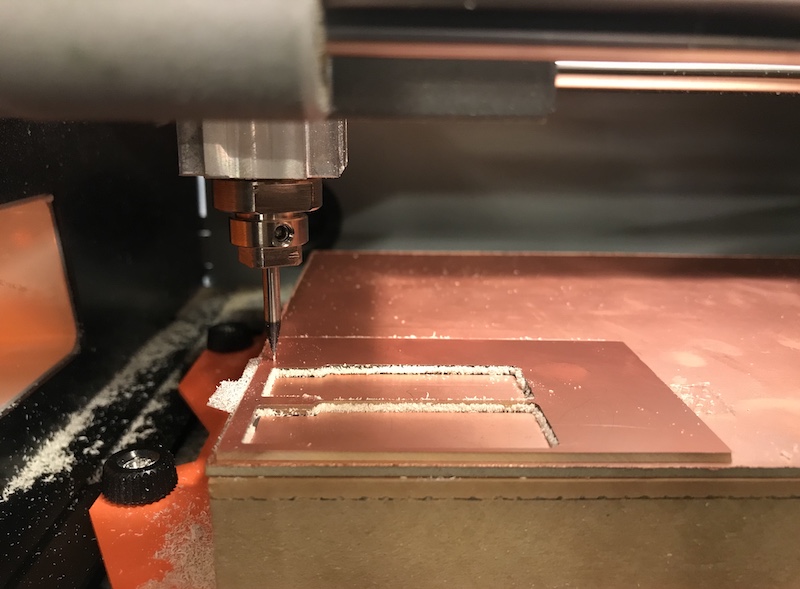
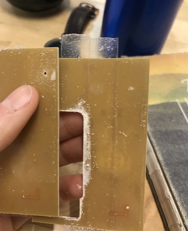
IMPORTANT: when screwing the bit, we need to avoid letting the endmill fall free on the surface or it can break and we need to make sure to hold it until it is screwed –> this is one of the mistakes I made and the result was not good as shown below…
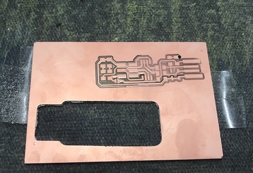
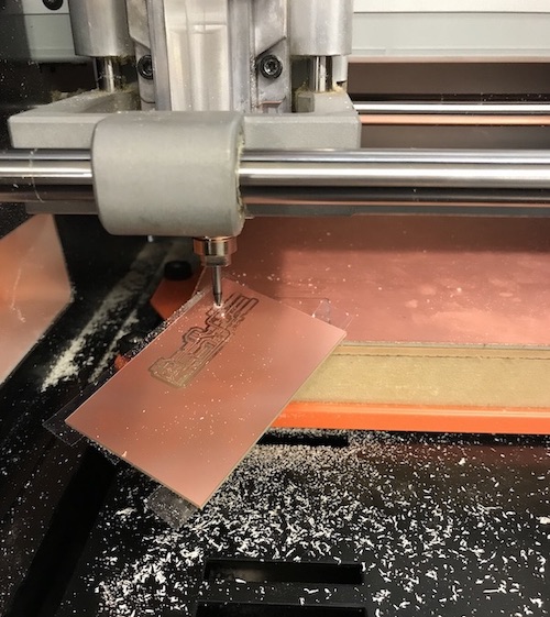
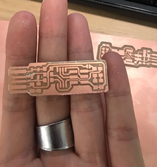
Now we are all set and can click on ‘send to the device ‘to start the milling. Once the traces are ready, we need to do the outline. First of all, we need to load the new image and then select ‘mill outline’. The settings this time will be different: cut depth is 0.024 and the max depth will be 0.072 (so the mill is gonna pass 3 times by the same place). The offset number is 1 given that the piece will be simply cut. Here I was too creative and decided to reduce it slightly because I thought there was too much material taken out from the sacrifical board. So I reduced each pass by 0.001 inches (so in total 0.003 inches difference) and the cut did not work! The piece came out after a couple of seconds.
|
|
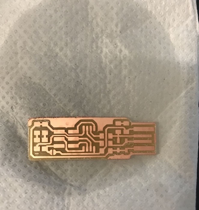
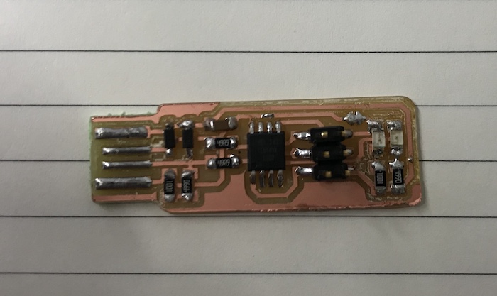
I did everything again from scratch and this time it worked. I then cleaned it with alcohol and passed to the next step: soldering!
|
|
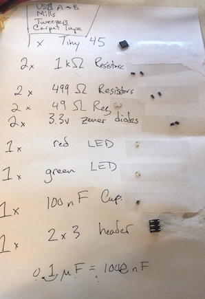
I never soldered before and there are a lot of things I should remember for the future. Most important one is to switch on the vent because breathing soldering material is not good… Our instructor gave us a good tip about how to write all electronics we need in a list and prepare them before starting the soldering.
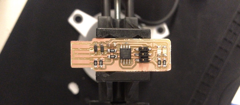
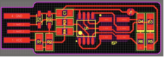
Important thing to remember is that some electronics have ‘sides’ that matter, while for others switching the side would not make the circuit work. For the micro-processor there is a little dot that tells you which side it is supposed to go. Resistors do not have sides, while LEDs and diodes do and they need to oriented correctly. Other important thing is that usually you need to first put soldering only for the purpose of keeping the piece steady to solder the other end (or ends) and, after the rest is done, it can be finalised.
Other things:
- Better to start from parts which are harder to sold and also from the most flat ones to makes it easier to proceed;
- Solder brail: it is useful to remove excess material;
- Heat gun: it helps removing eletronics which is soldered badly.
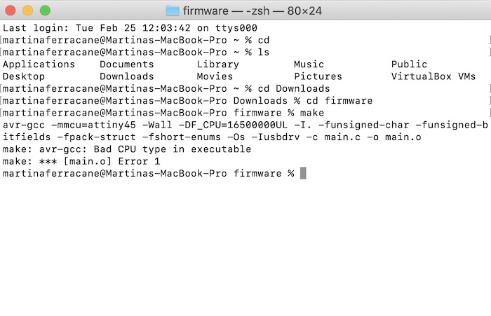
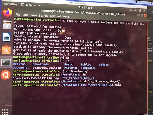
It was then time for the software installation. I followed the tutorial but I had a problem..
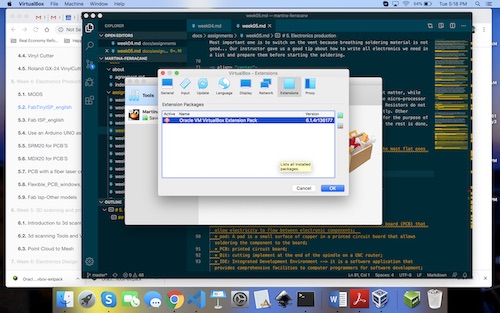
By googling, it seemed like this is a recurring problem for Catalina version of macOS. So, after some struggles, I decided to install a virtual machine with Ubuntu. Only problem I had was with an extension, and I am still not sure how to solve this problem.
iI fixed this. It was simply that wrong version of the installation pack for the extension.
Also, I am still not sure how to do drag and drops (I set them as bidirectional but doesn’t seem to work) and also did not manage to set up a common folder.
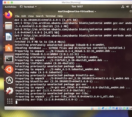
Anyway, in this way, the ‘make’ command worked and I was able to created the fts_firmware.hex file.
|
|
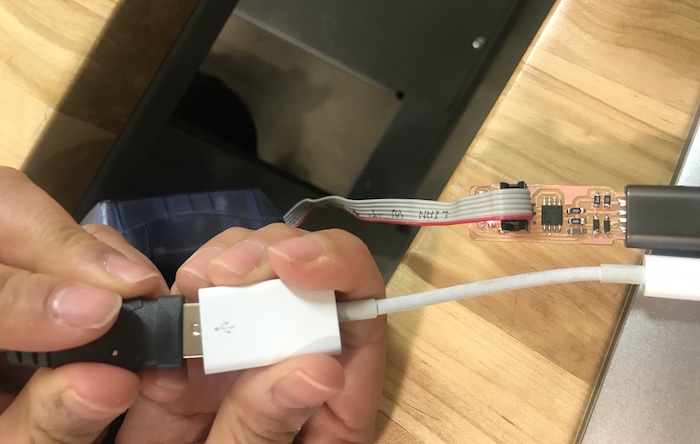
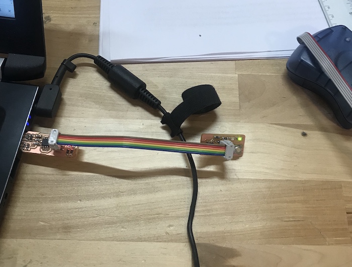
After, I plugged the ISP and connected it to my board. Important here is to remember the orientation. There is a small dot in the picture to understand the correct direction.
|
|
And this is where I couldn’t move forward:
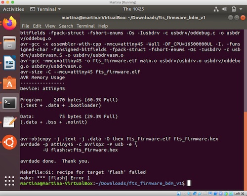
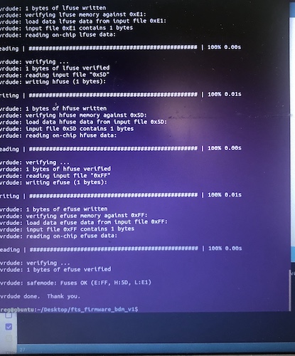
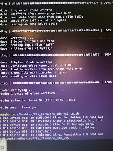
I was not able to do the make flash command. I googled and finally realised it was due to using a Mac, so I used another computer and it all went fine. I could run make fuses, verify that the USB was recognized with lsusb command and then run make rstdisbl.
|
|
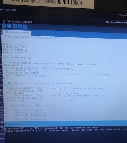
Once all seemed correct, I removed the bridge on the solder jumper and (together with the instructor) we programmed another board.
|
|
New words I never heard before:
* trace: The copper lines (sometimes aluminum) on a printed circuit board (PCB) that allow electricity to flow between electronic components;
* pad: A pad is a small surface of copper in a printed circuit board that allows soldering the component to the board;
* PCB: printed circuit board;
* Bit: cutting implement at the end of the spindle on a CNC router;
* IDE: Integrated Development Environment –> it is a software application that provides comprehensive facilities to computer programmers for software development;
* ISP: In-System Programming (ISP also stands for in-system programmer) –> it is the ability of some programmable logic devices, microcontrollers, and other embedded devices to be programmed while installed in a complete system, rather than requiring the chip to be programmed prior to installing it into the system;
* UDPI: Universal Programmer Debugger Interface (another type of ISP I think);
* micro-controller: it is a small computer on a single metal-oxide-semiconductor (MOS) integrated circuit chip;
* capacitor: a device used to store an electric charge, consisting of one or more pairs of conductors separated by an insulator.
Group assignment
The group assignment for this week was to characterize the design rules for our PCB production process. To do this, we traced the image in the assignments using a 1/64 inch bit and a 1/32 inch bit. This was still our first trial with the milling machine, so the traces did not come out nicely. Yet, it gave us some idea of the different use of the 2 bits.
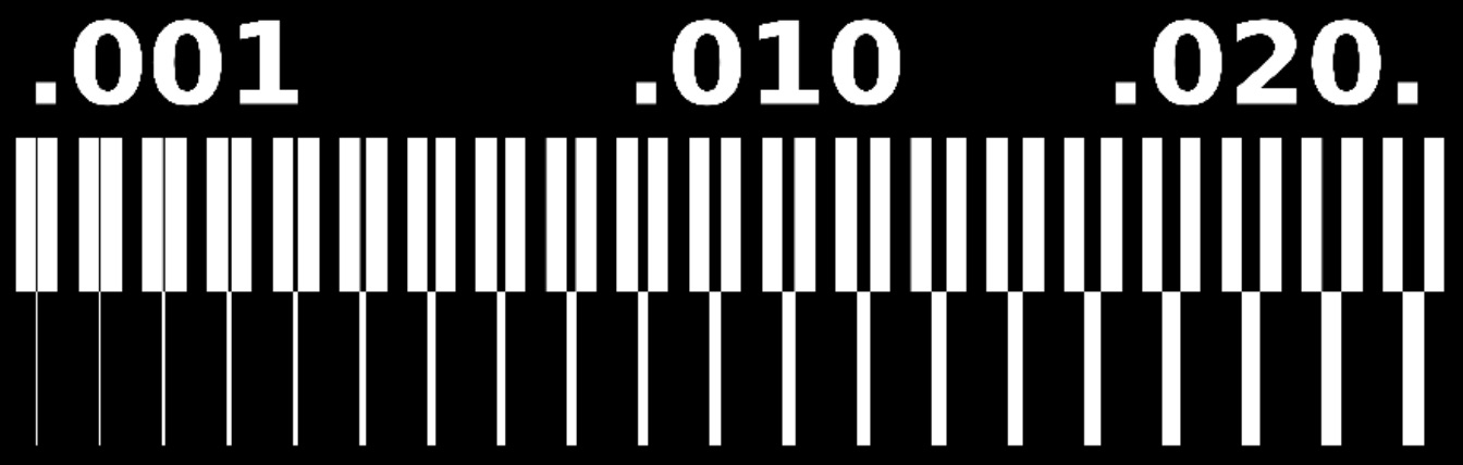
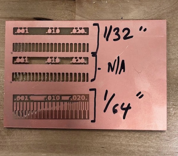
This was still our first trial with the milling machine, so the traces did not come out nicely.
Fun of the week
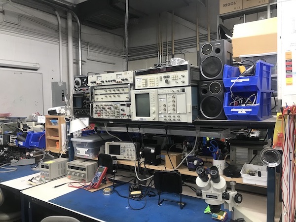
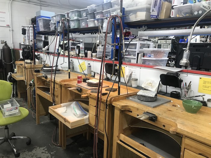
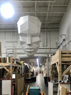
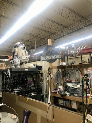
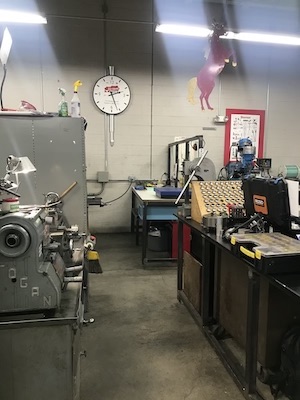
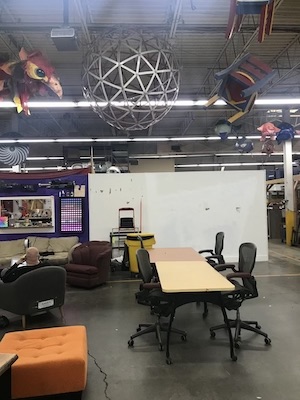
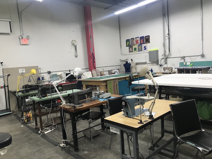
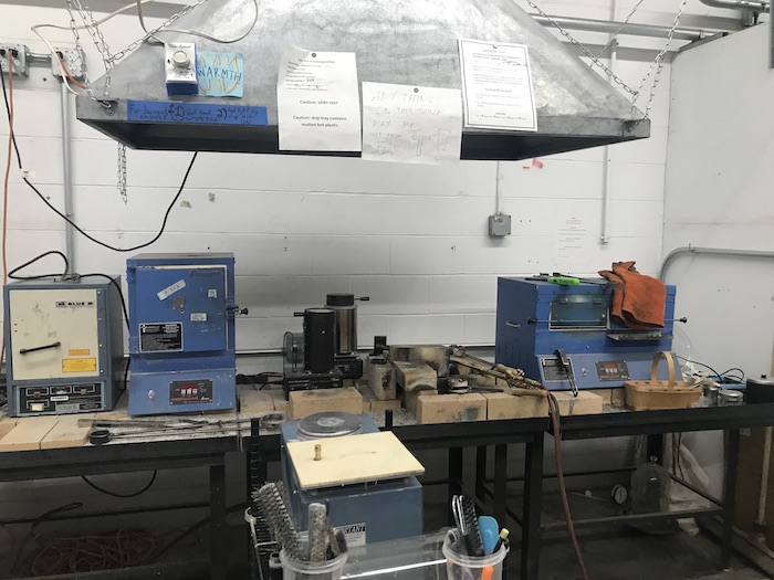
This week I discovered the Artisan’s Asylum.
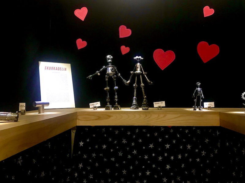
It’s a very special place. A community, a maker space, a co-working, an innovation space and much more. I really enjoyed the visit and the chat with the director and I hope to be able to bring some of the lessons learnt there to Sicily.
|
|
|
|
|
|
|
|