4. Computer controlled cutting
Time for computer controlled cutting. I had used in the past the laser cutter, but not the vynil and it was nice learning how to use it.
Vynil cutter
To learn how to use the vynil cutter, I took a basic course with our istructor at the lab and I also followed a training created by Fab@CIC on the Roland GX24 Vynil cutter, where I am going sometimes to use the machines :-)
The process of creating something with the vylin cutter has 5 steps:
1 . Selecting or producing an image on a design software of your choice.
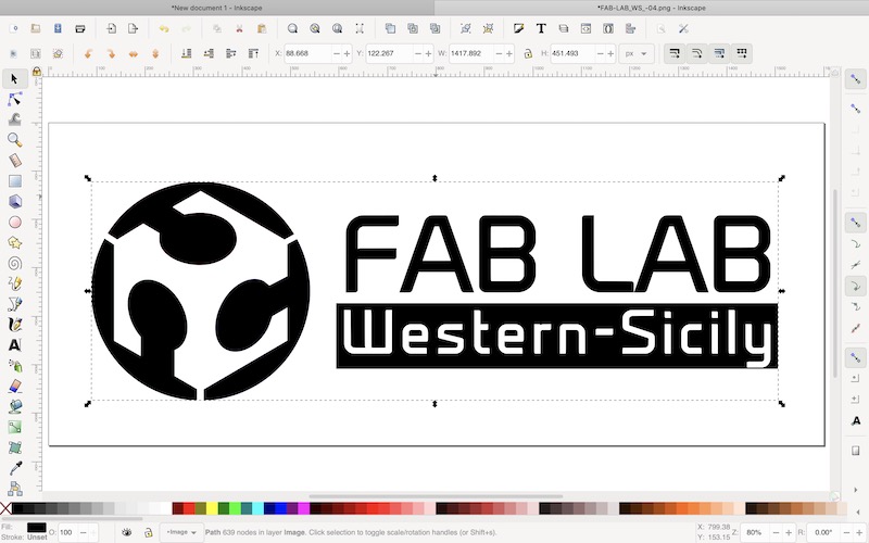
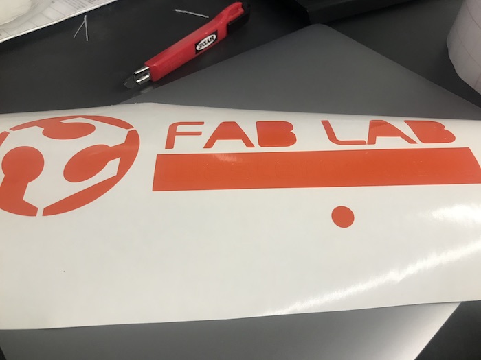
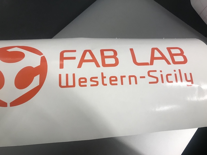
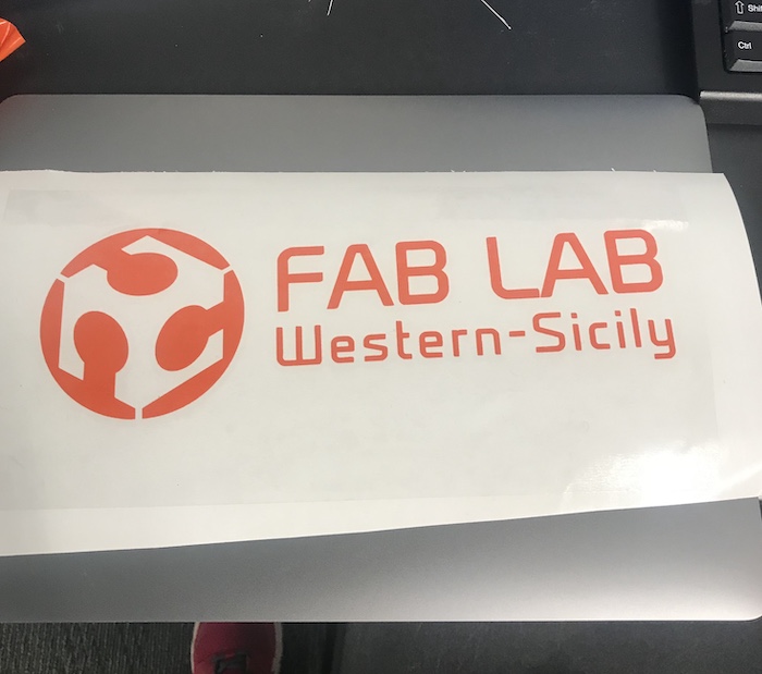
it’s important that the image has a clean border that completely closes the perimeter of your shape or set of shapes. I decided to try out the logos of the FabLab Western Sicily and of the Teens4Kids project (although I am not sure that the logo of the T4K project can be easily produced).
2 . Vectorizing your image (if necessary).
This can be done also in the Roland program by uploading an image and the do Object > Image Outline > Extract Contour Lines or, as the tutorial suggests, using inkscape and then do Path > Trace Bitmap and find the best Brightness Cutoff threshold for the image.Here there is also a guide on this. As I understand it, it can be either saved as an image or as .svg (but .svg is not direcly read by CutStudio).
3 . Outlining your image in Roland CutStudio.
I used the inkscape extension in the computer with the CutStudio program to open .svg directly in RolandCutStudio. It was quite useful and then all I needed to do was to go to Object > Image Outline > Extract Contour Lines.

4 . Loading, configuring, and executing your cut on the GX24.
The tutorial is quite detailed on what to do, so I’ll copy here a summary to use it in the future.
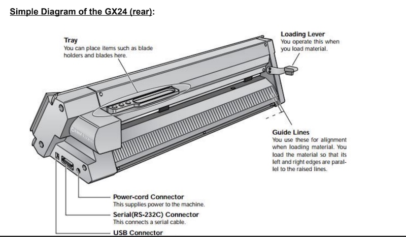
- Lower the “Loading Lever”.
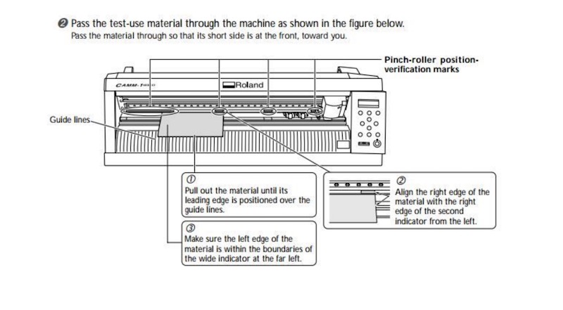
- Pass the material face-up (color side up) through the back of the cutter to the front.
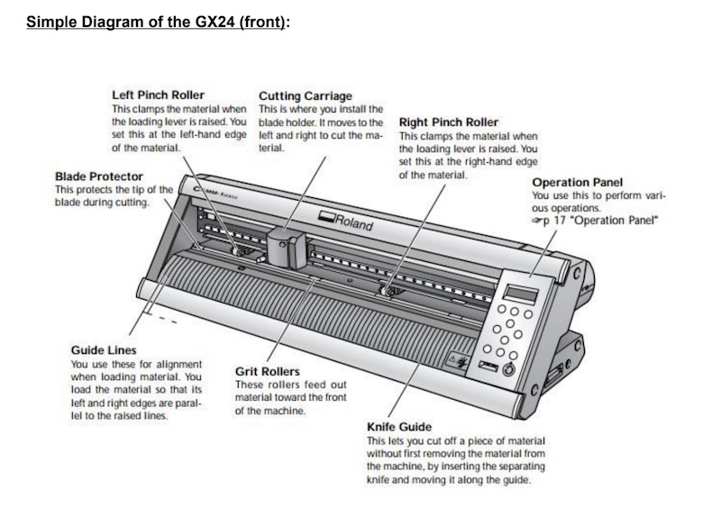
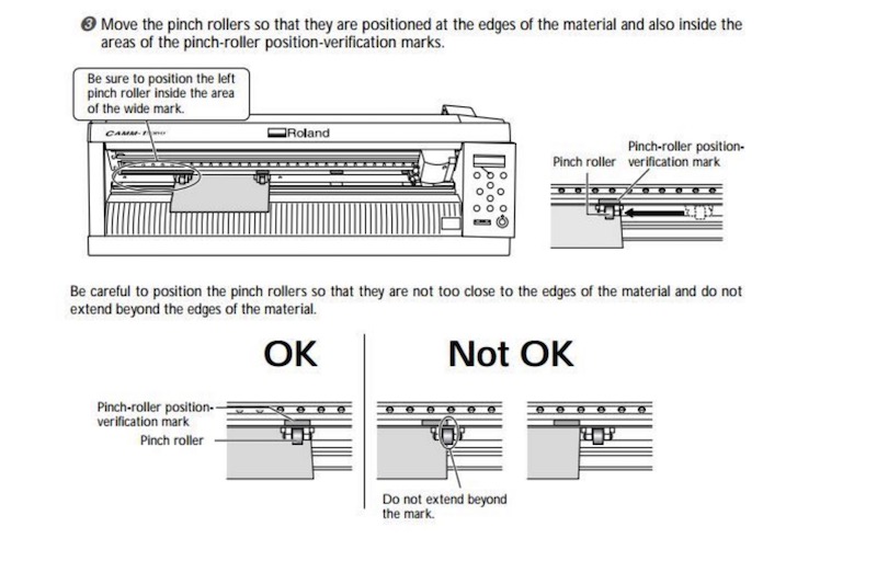
- Move the “Pinch Rollers” into an appropriate position based on the size of the vinyl roll or piece you have loaded. Each Pinch Roller must be situated within a region of the printing plane marked in white. These may be a little stiff at first, just be gentle but firm, lifting slightly while repositioning them.
- If you are cutting from a vinyl roll, ensure that there is a little slack in the material.
- Lift the Loading Lever so that it locks into place.
Then tutorial also suggests to use ‘edge’ and not ‘roll’ if we are using a roll. Then we need to report the size to the program. We do: - Go to File > Cutting Setup. - To the right of the printer’s name, click on Properties. - In the Size tab, click “Get from Machine.” - Resize your image as desired given the updated dimensions of the CutStudio project’s artboard. - Hit Print!
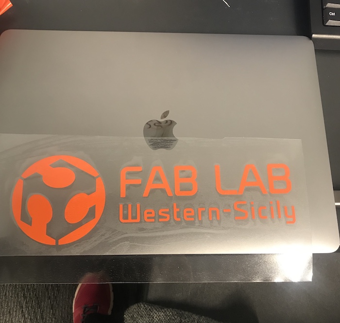
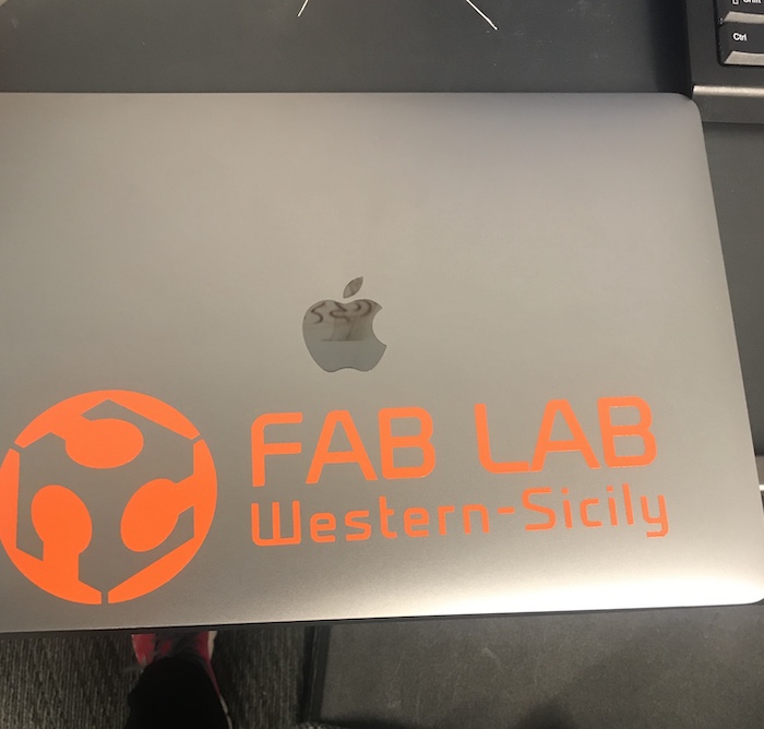
5 . “Weeding,” transferring, and placing your decal on the surface of your choice.

|
|
|
|
|
|
Laser cutter
I had used several times different laser cutters, but at Dassualt Systemes the laser cutter works through illustrator and in a way which is different from all the cutters I used before. I had to get acquainted with it so I spent an entire day trying out different settings and materials.
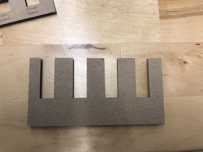
First thing I did was to make a design on inkscape to make some tests for the kerf and settings of the laser cutter. I had to choose the right colours and settings that the laser cutter would recognize. The laser cutter had already some default setting for the cutting of cardboard, so I started with those. The cardboard actually got on fire!!!
So I decided to try out a few different settings to find the perfect combination. After a few trial, the best combination for cutting the cardboard was 80 for power and 4 speed.
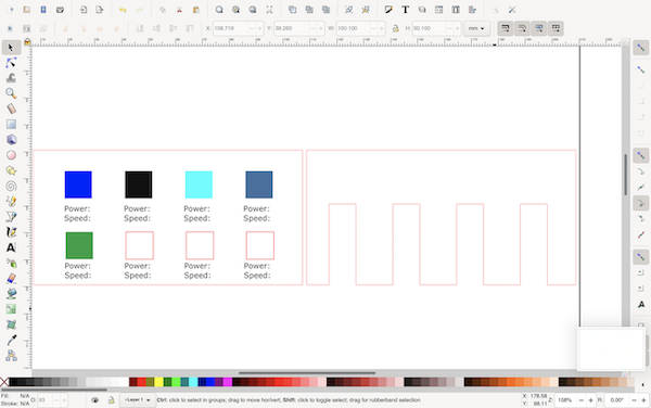
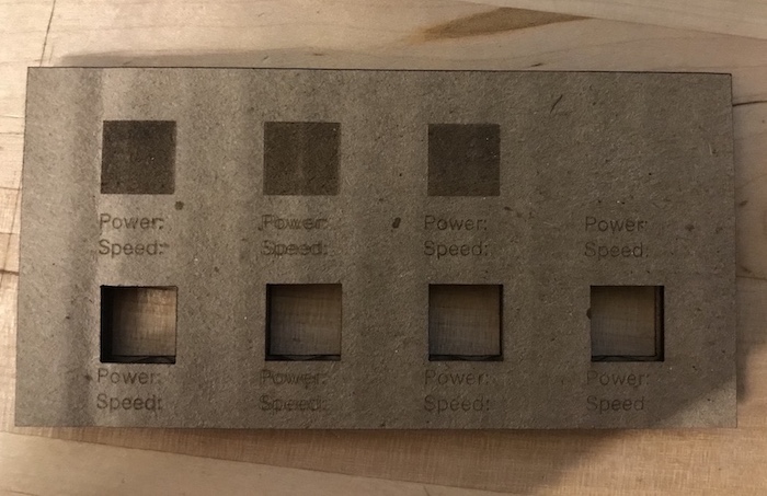
We put the settings into a new FabAcademy profile of the machine so we could try out other settings and create new profiles for the differnet materials. I wanted to try some engraving settings to find the best one. So, first of all, I created a settings palette in the profile and then created a file with some square of differnet colours (reflecting the palette).
|

|
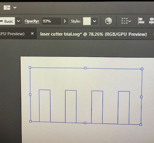
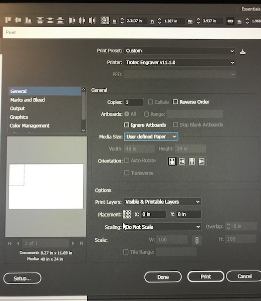
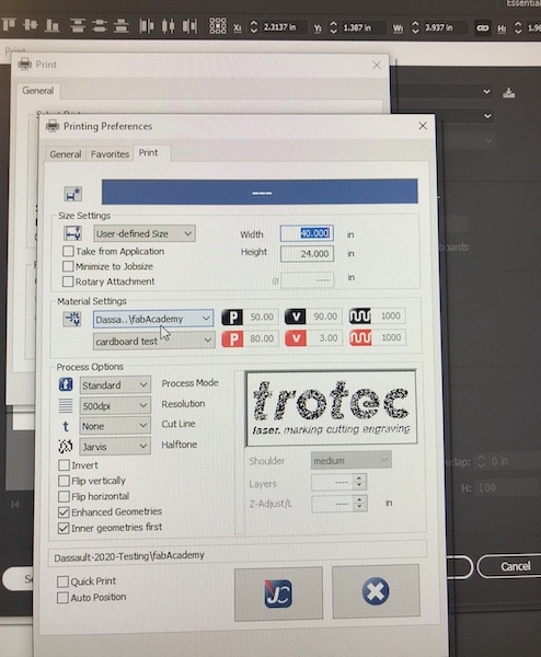
When I tried to cut it, I figured out there was a BIG problem with importing a file created with inkscape. It took me 2 hours to figure out what it was and then I realied it was the ‘opacity’ settig that, for some reason, automatically went to 93% instead of 100%, making it impossible for the laser cutter to recognise the colour for cutting or engraving. I then sent the file to print using illustrator. Important things to remember in the settings are to use ‘used defined paper’ (and make sure that the size of the paper is lower than the one of the laser cutter place –> otherwise it gives an error) and put place the model on top-left. Then I need to select the right material by clinking ‘setup’ and click print both in the setup page and in the settings page.
|
|
|
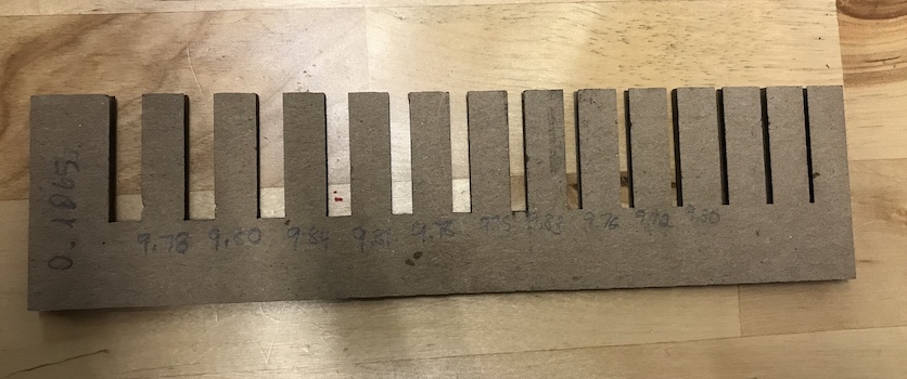
In the laser cutter program, I then only need to position the object right below the laser cutter head and hit ‘play’. Finally, everything worked out with the cardboard! With Zina, we cut a piece to measure the kerf of our machine which (at least for cardboard) is 0.1065mm.
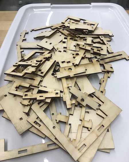
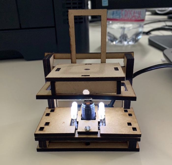
Then it was the turn of the playwood 3mm. I cut some pieces of a microscope created by the Waag Society in Amsterdam.
Notes: I did not know about the ‘rate’. Niel advises to use a lower one in case of material which melts or can ignite.
Group assignment
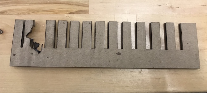
First of all, we cut a piece of cardboard to measure the kerf of our machine. We set up a series of columns of 1cm and measure each of them after cutting. On average for the 10 pieces the kerf was 0.1065mm, although it was slightly different for each of them.
Regarding the power and speed, we first tried the standard settings of the machine for cardboard and realised the power was actually too strong (the cardboard got on fire…). So we tested out some different settings until we found those that worked best for cardboard: * Power: 80; * Speed: 4; * Rate: 1000.
We then also tested some settings for engraving.
Parametric design
I will work on the parametric design (and creating the construction kit) today and tomorrow. I have tested some softwares and decided to use freeCAD for this exercise. One important thing I will do it to make this miscroscope design paramentric. In the Teens4Kids project, we use this microscope as a workshop for kids, but we always have the problem of having to adjust the design when the input material has different sizes. In fact, there are a lot of pieces than need to fit with each other and a different of 0.5mm already has a big impact on the final structure. So I will make the design paramentric and share it online for others to use.
So.. first issue I encountered was in downloading freeCAD. For some reason, download from the website gave a broken link for MAC so I looked for alternatives and finally found one solutions here.
Interesting link: https://www.makercase.com/#/kerfbox