11. Input devices
This week I tried to integrate my assignment with my final project since my project is loosely based on heating and cooling I have to measure the temperature. for which I have am planning on using thermister but to measure it properly I might have to use multiple inputs.
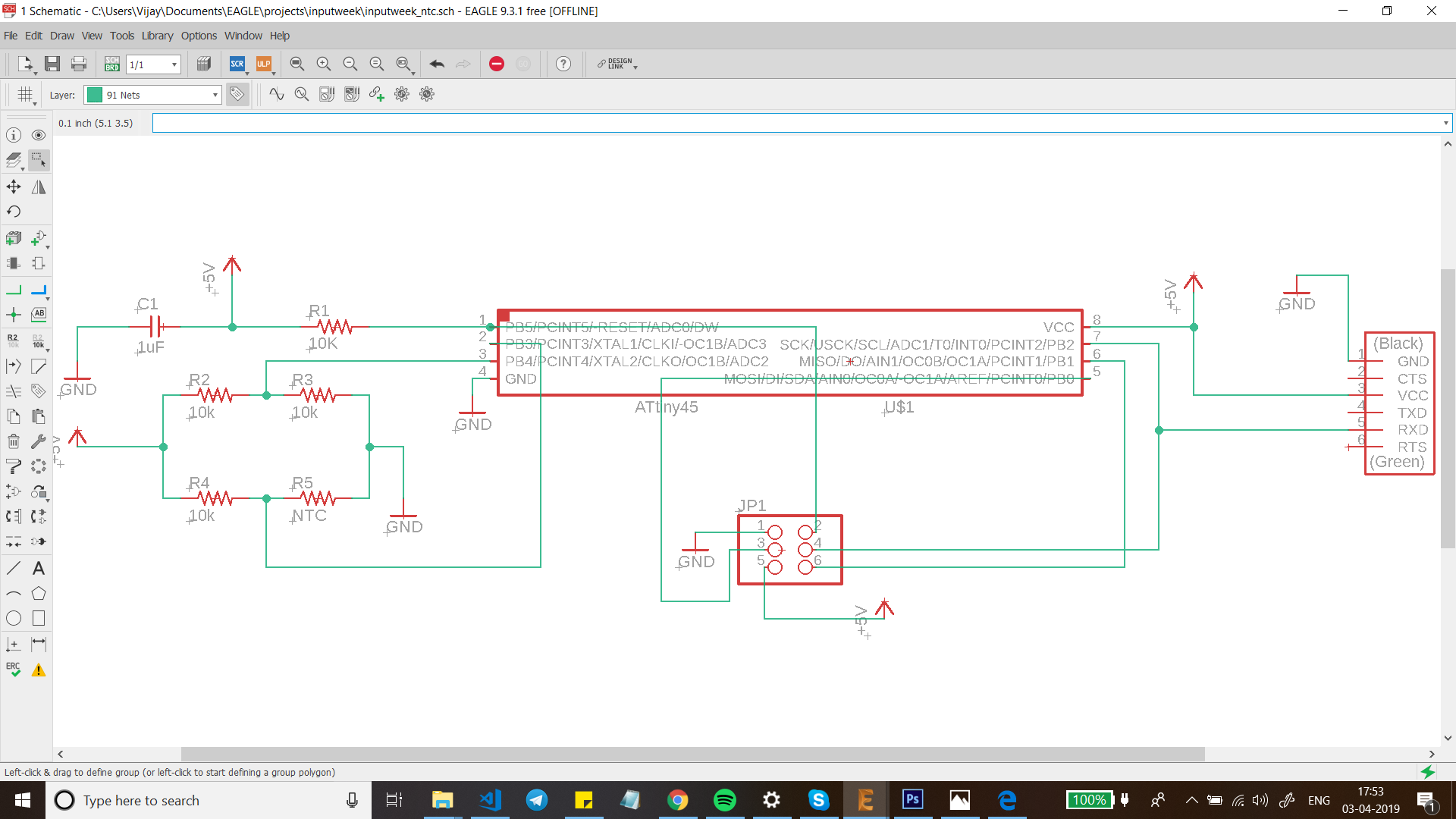
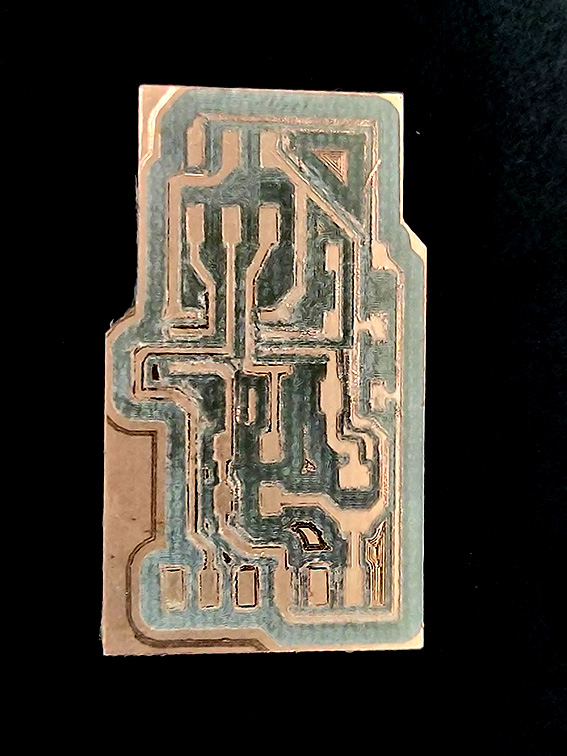
PCB design
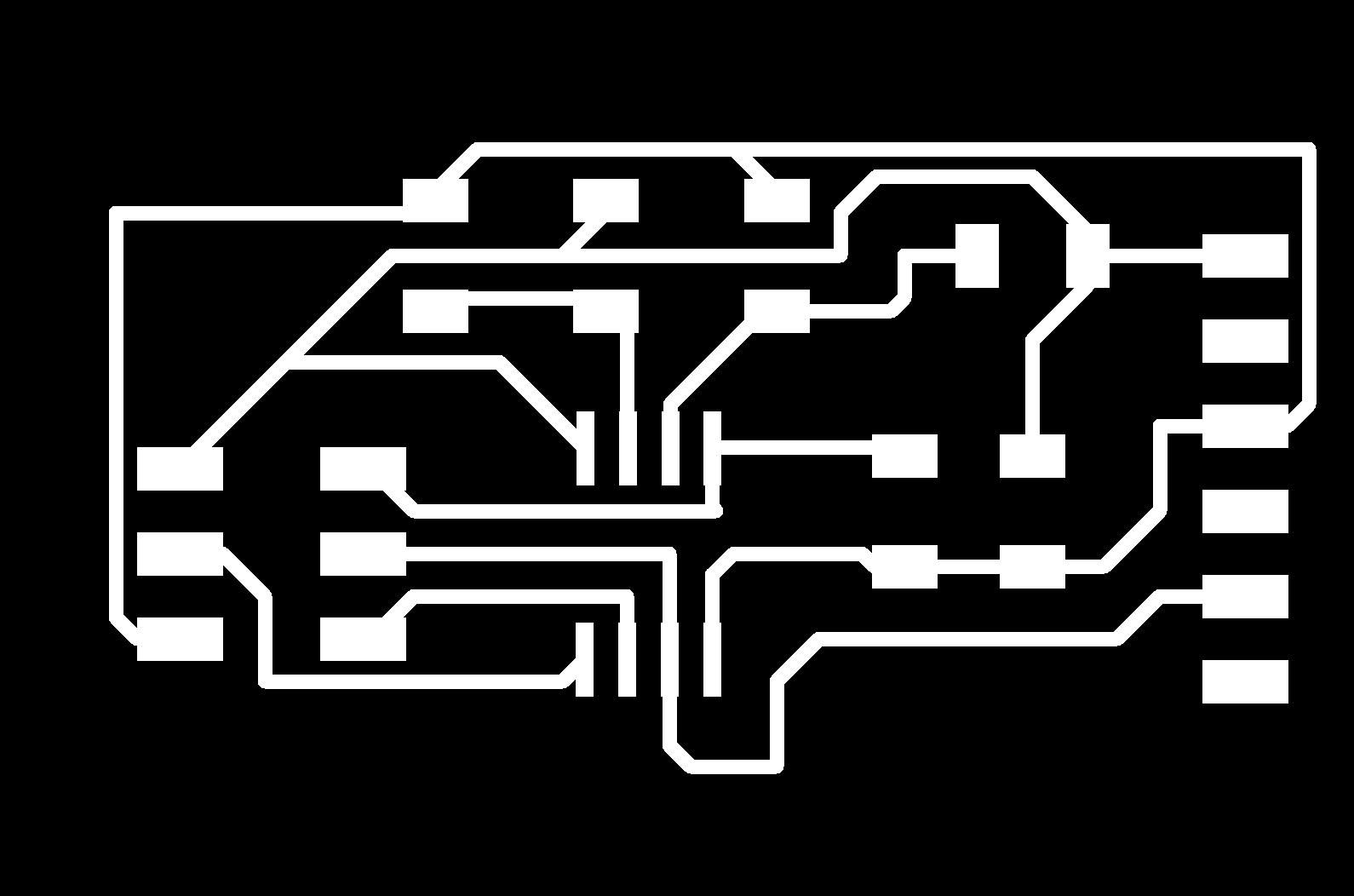
Truth be told, I simply tried to replicate the circuit design in the Fabacademy archives. I redrew the circuit in eagle and exported the image with a resolution of 500 DPI however, I hit a snag while milling the board I missed the Image sizing step while I was milling the board where I forgot to change the size of the image because of which the PCB traces were milled in the wrong dimensions.
The dimensions were L: 70 mm, W: 40mm where they should have been L: 40.4mm, W: 26.8mm.
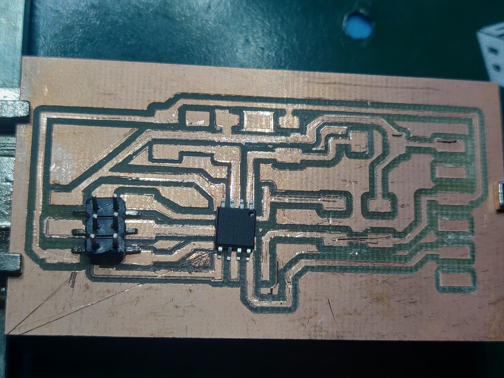
The second mistake was not realizing that the PCB was in the wrong dimensions till I sat down to solder the components.
After redoing the board once again there are still some things i have to fix.
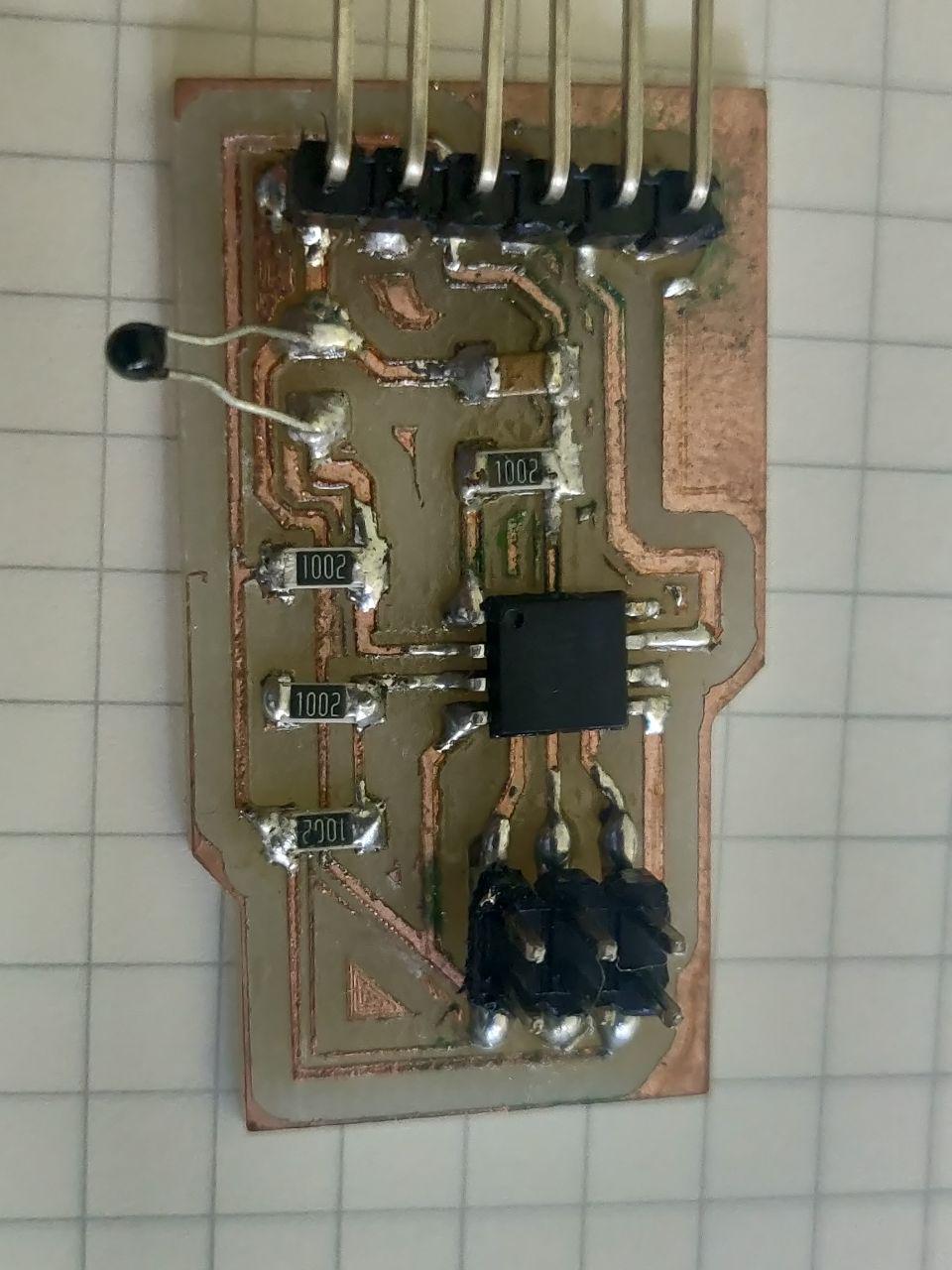
Understanding the circuit
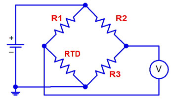
The circuit has an ATTiny 45, 23Pin Header, and Ftdi pin header and one resistor I am using a thermister for which one has to use a circuit is known as Bridge circuit which is used to measure an unknown electrical resistance by balancing two legs of a bridge circuit, one leg of which includes the unknown component. In this circuit we are using wheatstone bridge*.
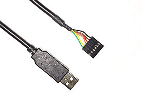
We use a 2*3 Pin header to communicate with the ISP which in turn communicates with the computer. basically we use the header to load the code into the ATTiny45.
Whereas the FTDI pin header is used to read the signal output given by the sensor.
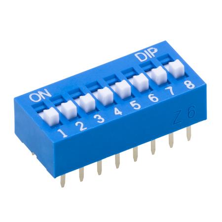
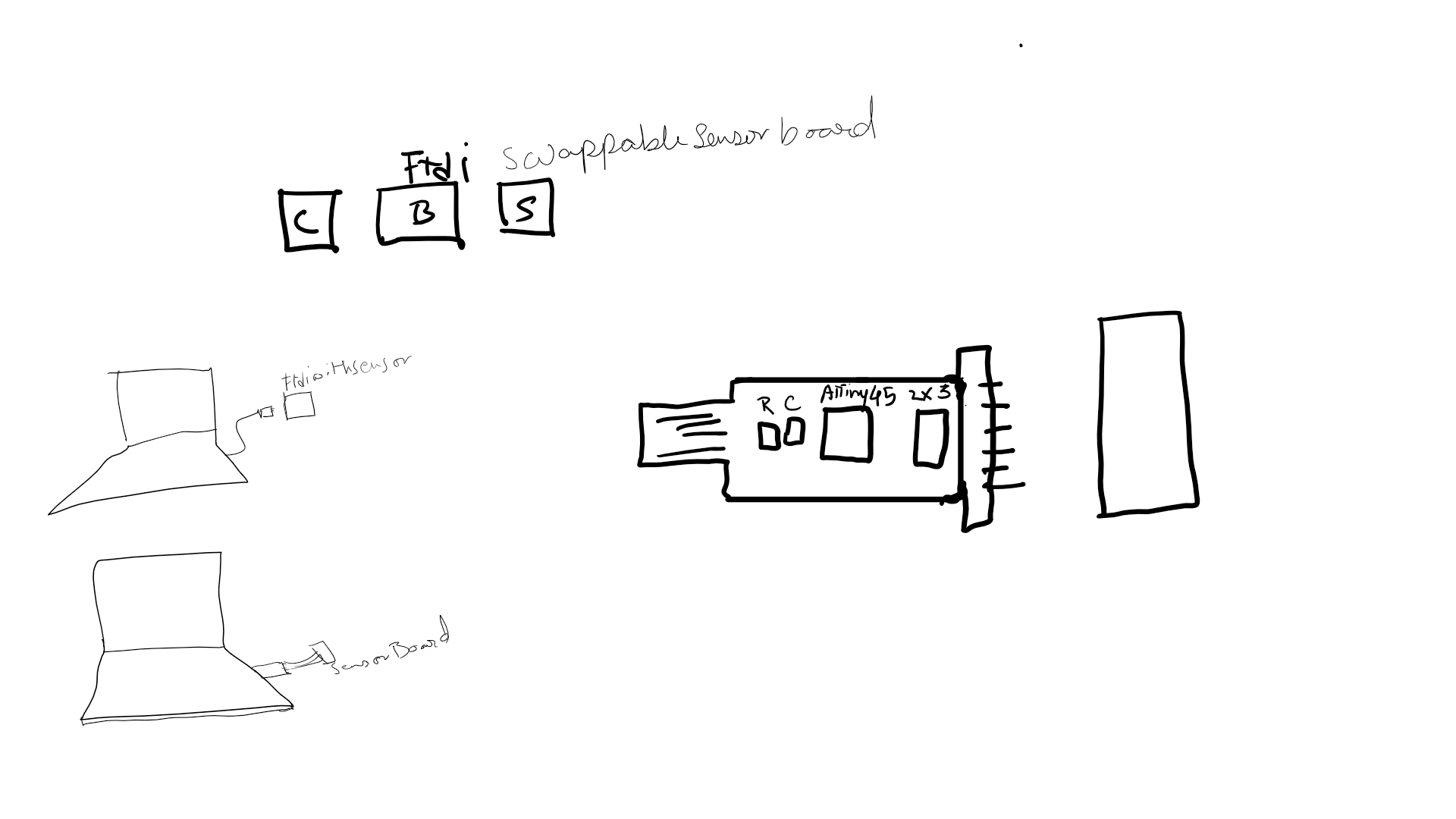
Side Project
As a side project I wanted to make a universal board for the sensors we have in the fablab, so that we can use a single board to interface with multiple sensors. After discussing with my Remote Guru, Jason He suggested me to use a dip switch initialy and then I should try to code a program in which the software or program will automatically detect the relevant portion or code to read the sensor data.
Concept Sketch
Sorry for the crude sketch, this was my first time using a graphic tablet.
Code
Since I replicated the board I planned on using the code from the Archive.
//
//
// hello.temp.45.c
//
// thermistor hello-world
//    9600 baud FTDI interface
//
// Neil Gershenfeld
// 10/27/10
//
// (c) Massachusetts Institute of Technology 2010
// This work may be reproduced, modified, distributed,
// performed, and displayed for any purpose. Copyright is
// retained and must be preserved. The work is provided
// as is; no warranty is provided, and users accept all
// liability.
//

#include <avr/io.h>
#include <util/delay.h>

#define output(directions,pin) (directions |= pin) // set port direction for output
#define set(port,pin) (port |= pin) // set port pin
#define clear(port,pin) (port &= (~pin)) // clear port pin
#define pin_test(pins,pin) (pins & pin) // test for port pin
#define bit_test(byte,bit) (byte & (1 << bit)) // test for bit set
#define bit_delay_time 102 // bit delay for 9600 with overhead
#define bit_delay() _delay_us(bit_delay_time) // RS232 bit delay
#define half_bit_delay() _delay_us(bit_delay_time/2) // RS232 half bit delay
#define char_delay() _delay_ms(10) // char delay

#define serial_port PORTB
#define serial_direction DDRB
#define serial_pin_out (1 << PB2)

void put_char(volatile unsigned char *port, unsigned char pin, char txchar) {
   //
   // send character in txchar on port pin
   //    assumes line driver (inverts bits)
   //
   // start bit
   //
   clear(*port,pin);
   bit_delay();
   //
   // unrolled loop to write data bits
   //
   if bit_test(txchar,0)
      set(*port,pin);
   else
      clear(*port,pin);
   bit_delay();
   if bit_test(txchar,1)
      set(*port,pin);
   else
      clear(*port,pin);
   bit_delay();
   if bit_test(txchar,2)
      set(*port,pin);
   else
      clear(*port,pin);
   bit_delay();
   if bit_test(txchar,3)
      set(*port,pin);
   else
      clear(*port,pin);
   bit_delay();
   if bit_test(txchar,4)
      set(*port,pin);
   else
      clear(*port,pin);
   bit_delay();
   if bit_test(txchar,5)
      set(*port,pin);
   else
      clear(*port,pin);
   bit_delay();
   if bit_test(txchar,6)
      set(*port,pin);
   else
      clear(*port,pin);
   bit_delay();
   if bit_test(txchar,7)
      set(*port,pin);
   else
      clear(*port,pin);
   bit_delay();
   //
   // stop bit
   //
   set(*port,pin);
   bit_delay();
   //
   // char delay
   //
   bit_delay();
   }

int main(void) {
   //
   // main
   //
   static char chr;
   //
   // set clock divider to /1
   //
   CLKPR = (1 << CLKPCE);
   CLKPR = (0 << CLKPS3) | (0 << CLKPS2) | (0 << CLKPS1) | (0 << CLKPS0);
   //
   // initialize output pins
   //
   set(serial_port, serial_pin_out);
   output(serial_direction, serial_pin_out);
   //
   // init A/D
   //
   ADMUX = (0 << REFS2) | (0 << REFS1) | (0 << REFS0) // VCC ref
      | (0 << ADLAR) // right adjust
      | (0 << MUX3) | (1 << MUX2) | (1 << MUX1) | (1 << MUX0); // 20(PB4-PB3)
   ADCSRA = (1 << ADEN) // enable
      | (1 << ADPS2) | (1 << ADPS1) | (1 << ADPS0); // prescaler /128
   ADCSRB = (1 << BIN); // bipolar mode
   //
   // main loop
   //
   while (1) {
      //
      // send framing
      //
      put_char(&serial_port, serial_pin_out, 1);
      char_delay();
      put_char(&serial_port, serial_pin_out, 2);
      char_delay();
      put_char(&serial_port, serial_pin_out, 3);
      char_delay();
      put_char(&serial_port, serial_pin_out, 4);
      char_delay();
      //
      // initiate conversion
      //
      ADCSRA |= (1 << ADSC);
      //
      // wait for completion
      //
      while (ADCSRA & (1 << ADSC))
         ;
      //
      // send result
      //
      chr = ADCL;
      put_char(&serial_port, serial_pin_out, chr);
      char_delay();
      chr = ADCH;
      put_char(&serial_port, serial_pin_out, chr);
      char_delay();
      }
   }
Gallery