8. Input devices
Third week of confinement. we try the input devices.
Research
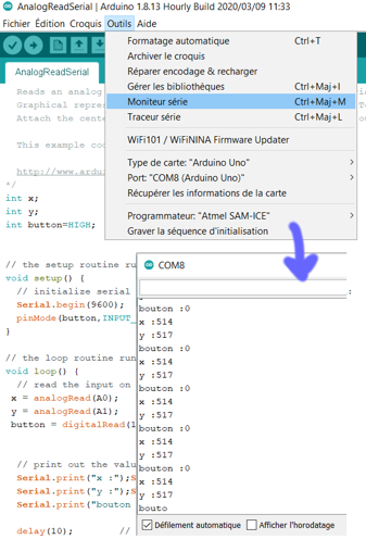
We learn to use input devices with arduino. With no output devices, the way to check that Arduino works well in to use monitor
how to check that the code runs correctly ?
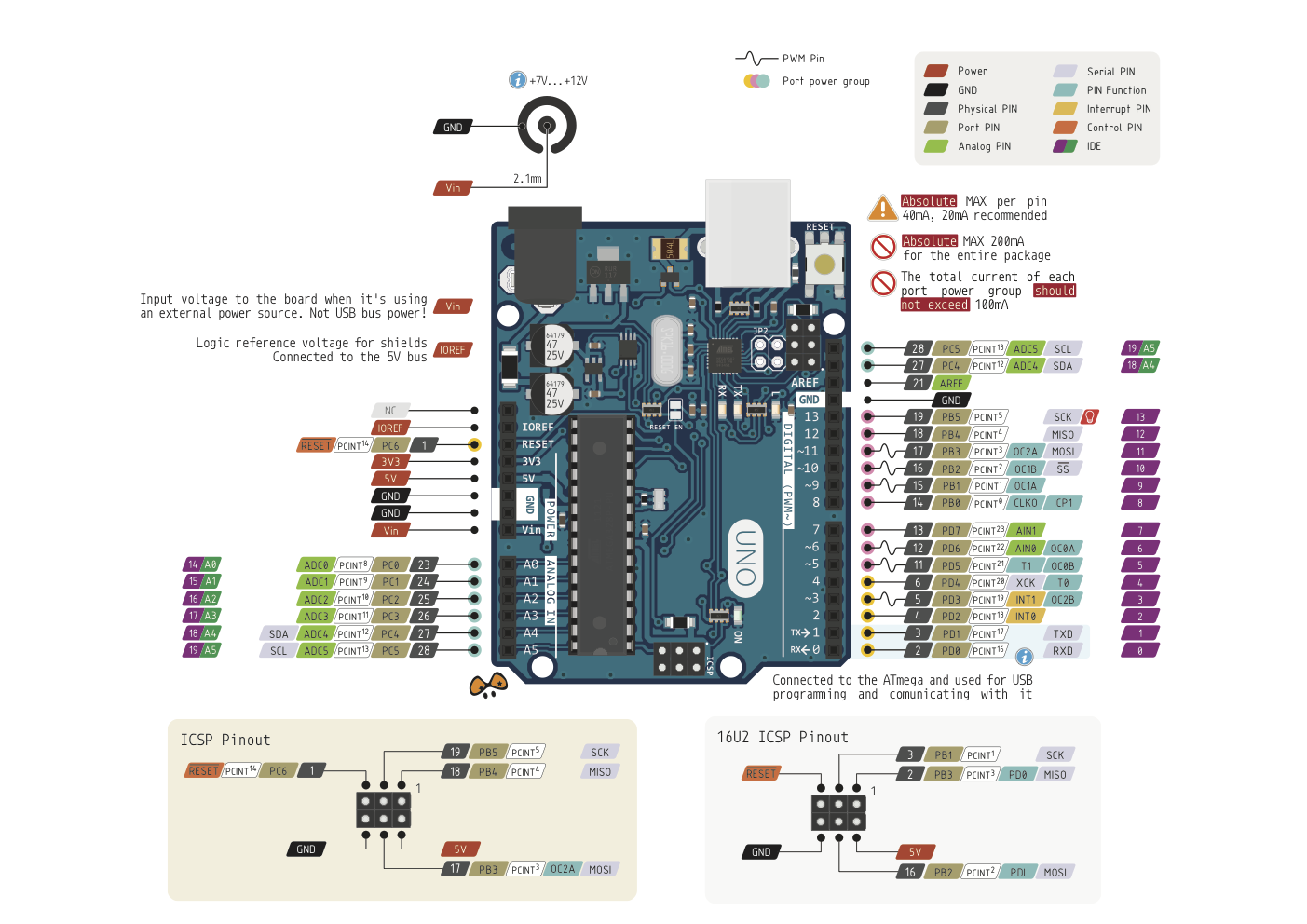
where to connect on Arduino ?
 .
.
Let’s try different sensors with arduino
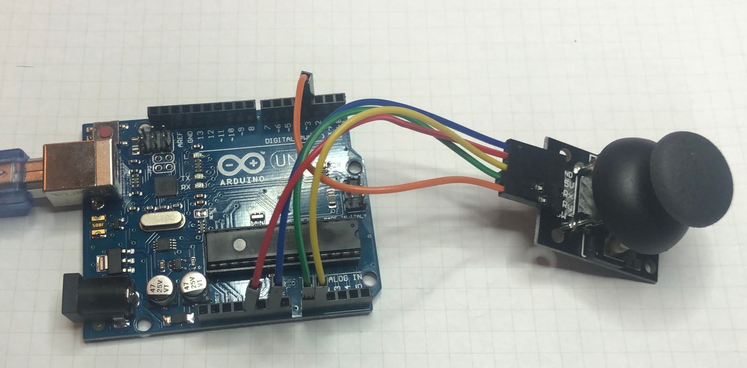
KYO23 Joystick
int x;
int y;
int button=HIGH;

// the setup routine runs once when you press reset:

void setup() {
  // initialize serial communication at 9600 bits per second:
  Serial.begin(9600);
  pinMode(button,INPUT_PULLUP);
}


void loop() {

 x = analogRead(A0);
 y = analogRead(A1);
 button = digitalRead(1);


  // print out the value you read:
  Serial.print("x :");Serial.println(x);
  Serial.print("y :");Serial.println(y);
  Serial.print("bouton :");Serial.println(button);

  delay(10);        // delay in between reads for stability
}
```
this code does not work when your press the button. The loop stops
// Module KY023
// For more info see http://tkkrlab.nl/wiki/Arduino_KY-023_XY-axis_joystick_module
int JoyStick_X = A0; // x
int JoyStick_Y = A1; // y
int JoyStick_Z = 3; // key
void setup ()
{
  pinMode (JoyStick_X, INPUT);
  pinMode (JoyStick_Y, INPUT);
  pinMode (JoyStick_Z, INPUT_PULLUP);
  Serial.begin (9600); // 9600 bps
}
void loop ()
{
  int x, y, z;
  x = analogRead (JoyStick_X);
  y = analogRead (JoyStick_Y);
  z = digitalRead (JoyStick_Z);
  Serial.print (x, DEC);
  Serial.print (",");
  Serial.print (y, DEC);
  Serial.print (",");
  Serial.println (z, DEC);
  delay (100);
}
```
this one work.
First problem, i used the Pin 1. when you change for 3, the loop does not stop when you press the button
and when you move the joystick, data change from 0 to 1023 for the analogic input and for the button, it’s 1 or 0.
 .
.
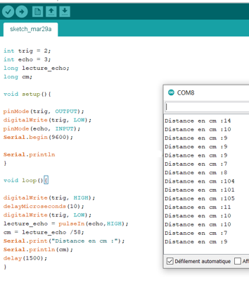
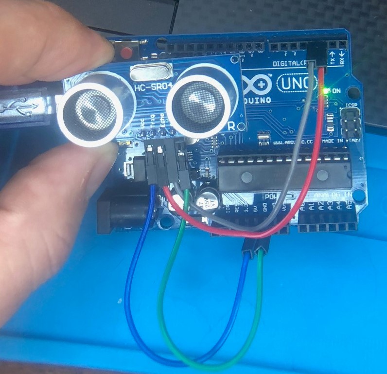
sonar sensor HC-SR04
int trig = 2;
int echo = 3;
long lecture_echo;
long cm;

void setup(){

pinMode(trig, OUTPUT);
digitalWrite(trig, LOW);
pinMode(echo, INPUT);
Serial.begin(9600);

}

void loop(){

digitalWrite(trig, HIGH);
delayMicroseconds(10);
digitalWrite(trig, LOW);
lecture_echo = pulseIn(echo,HIGH);
cm = lecture_echo /58.3;
Serial.print("Distance en cm :");
Serial.println(cm);
delay(1500);
}
```
we need to know the speed of the sound in the air : 343 m/s and the signal make a round trip so it’s a double distance, and the result will be in µs.
that why you need to divide the result by (10000/343)x2= 58.3 to have a measurement in cm
 .
.
 .
.
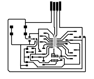
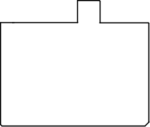
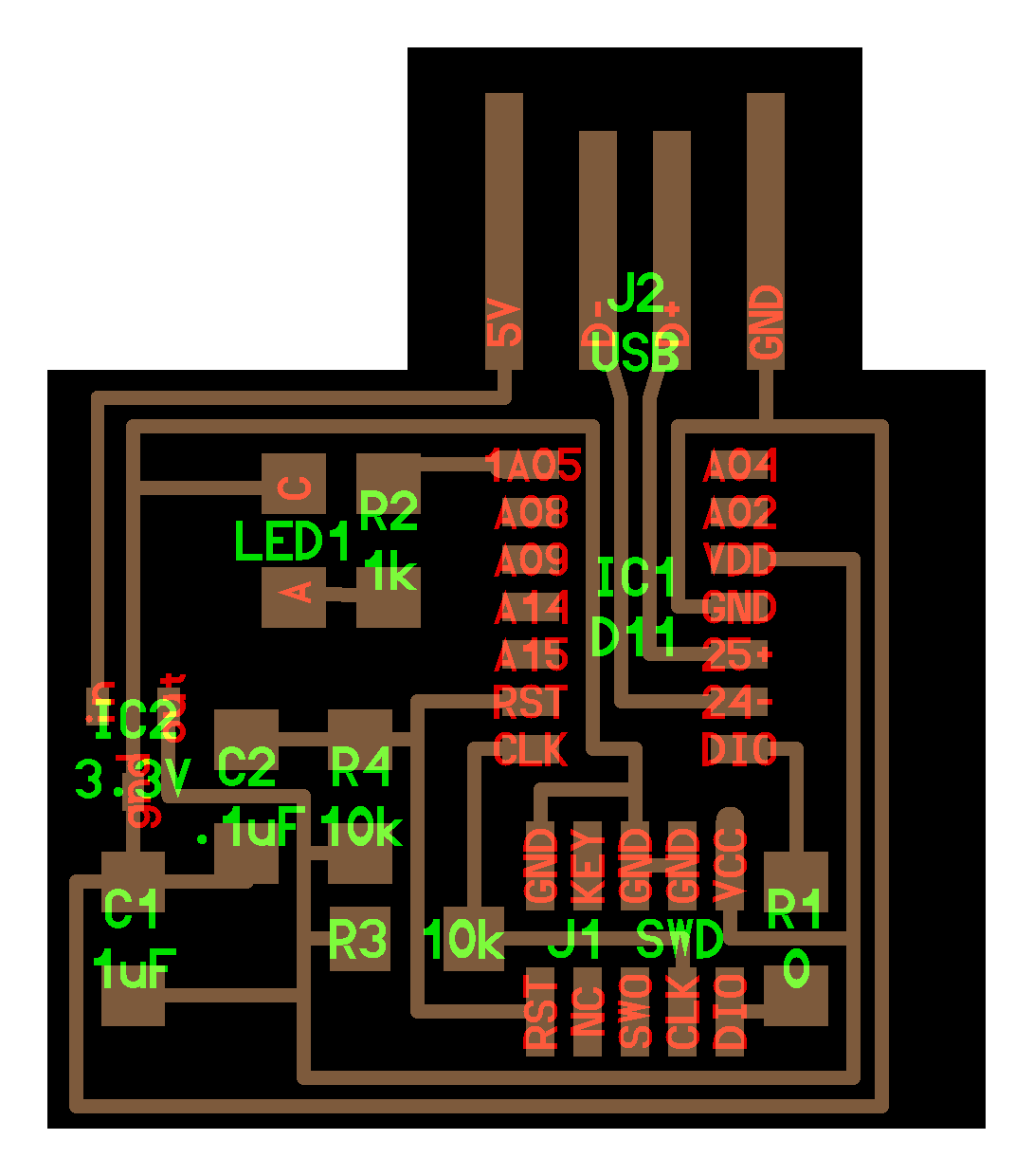
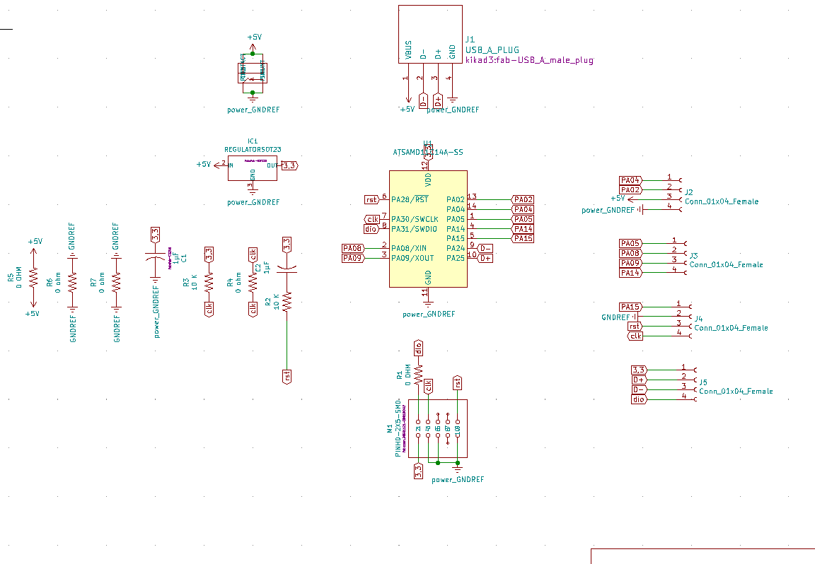
A PCB
Because of the pandemic, we have to make a PCB ‘swiss knife’ : a board that you can use for many things, because of his adaptability, during the next weeks. We’ll be able to use it with different devices, component, board and breadboard.
we use as a base this board, because ADM11C is a component that i use since the beginning of the academy and Neil told us that the capacitor on the reset pin improve the stability of the component.
 .
.
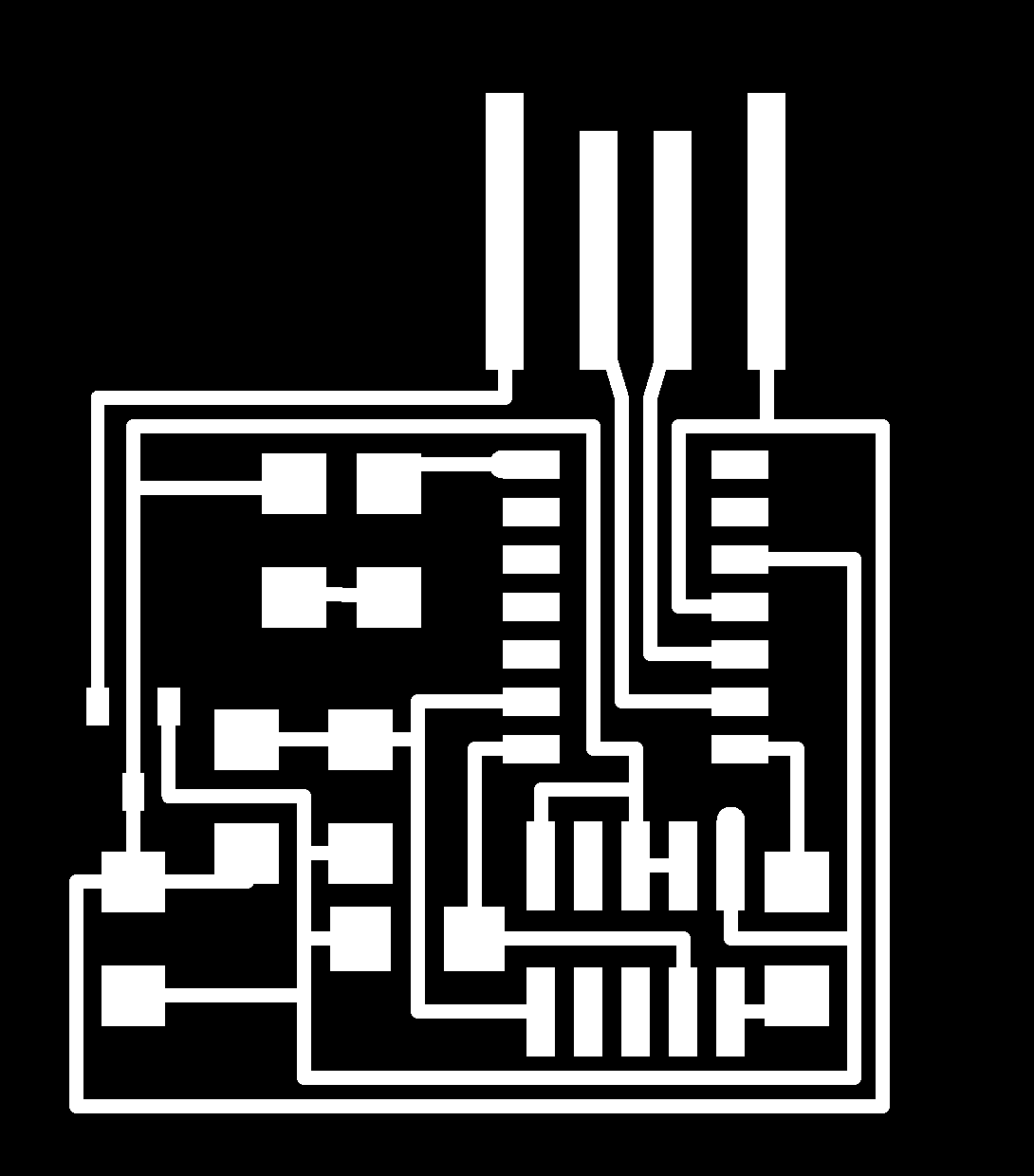
So i removed the LED which is not essential for the microcontroller operation. I added connectors to connect all the pin of the SAMD.
I also add a jack 5v connector, and on the free plug of the connectors, i add 3,3 v, 5v, 2 ground
All the component are in the inventory of the fabacademy. all symbols and footprints can be found here especialy the USB male trace.
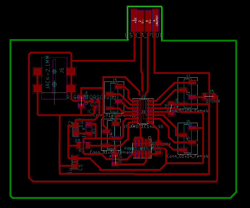
the power jack PJ-002AH-SMT-TR
the 4 pins female connector NPTC041KFXC-RC
Because of the design, i needed to add also some 0 ohm resistor as bridges over tracks because some were crossing and to be sure to succeed the mill, i add also some 0 ohm resistor as bridges over tracks.