4. Electronics production
This week i make an in-circuit programmer by milling and stuffing the PCB, and test it.
the material
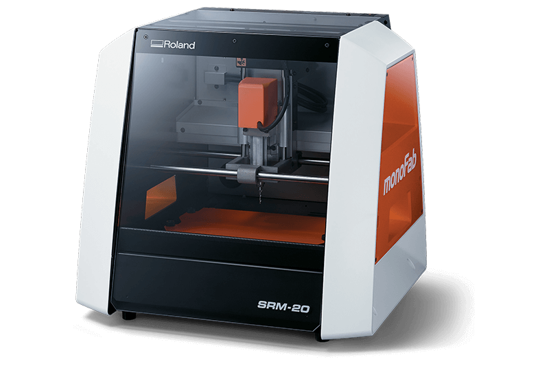
the milling machine
we use the Roland SRM 20. the machine can mill Modeling Wax, Chemical Wood, Foam, Acrylic, Poly acetate, ABS, PC board (PCB)
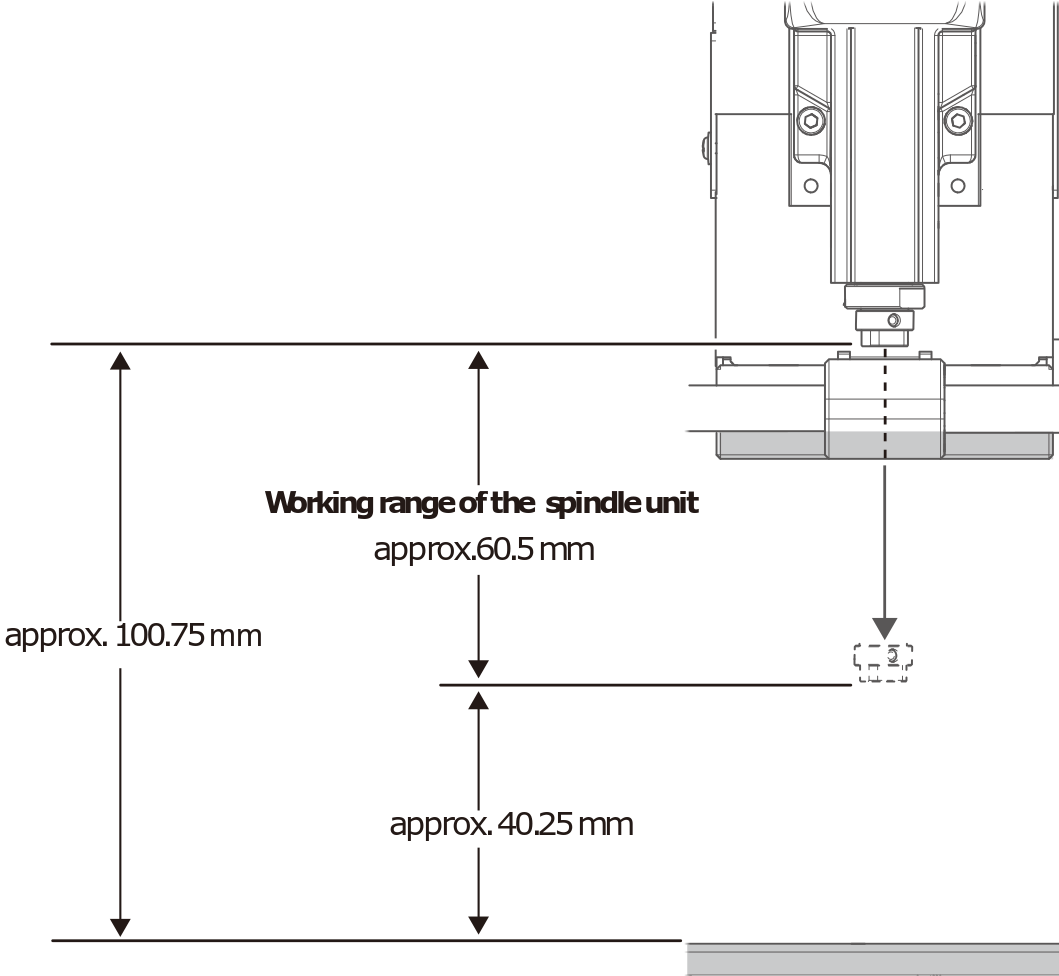
0,4 or 1 mm endmill is small and, even with the lowest position, the spindle cannot reach the PCB blank on the table. You need some extra spacers. We do that with several MDF joined layers, which become the sacrificial board when the milling is too deep.
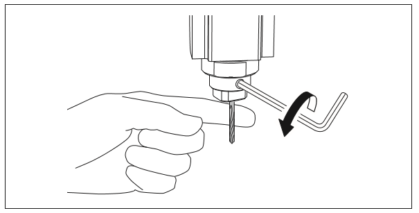
You have to be carefull when you install the endmill because it’s very fragile. Don’t let it fall
The machine it self has a “hardware” zero position (x,y and z) but your job a one as well. you will have to set the 0 level of the Z axis of your job, depending on the attachment of the endmill . The x,y depends on where the PCB blank is installed and also depends on your design
this machine accept 2 Languages : RML-1 (roland standard) .rml , NC code (general language) .nccode
The soldering station and small equipment
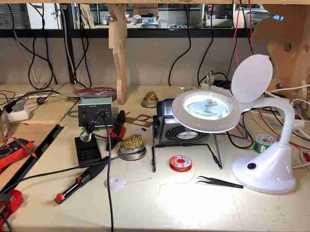
Our soldering station is the weller PU 81
and we use it at 400°c
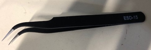
all our boxes, tools and tweezers are ESD, to avoid from static electricity problems.
box for component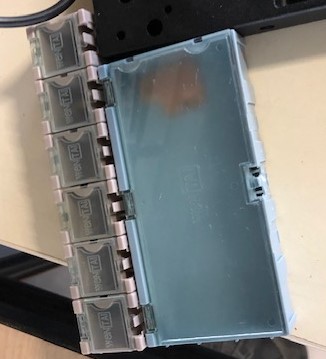
we use Brass Tip Cleaner, magnifying lamp on stand, desoldering braid or pump to vaccum a missed weld
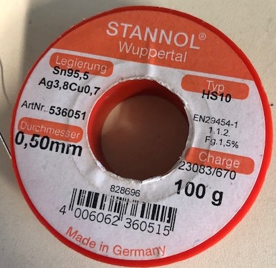
The solder wire without lead
Characterisation of the milling machine
with linetest_trace and linetest_interior
we drawed
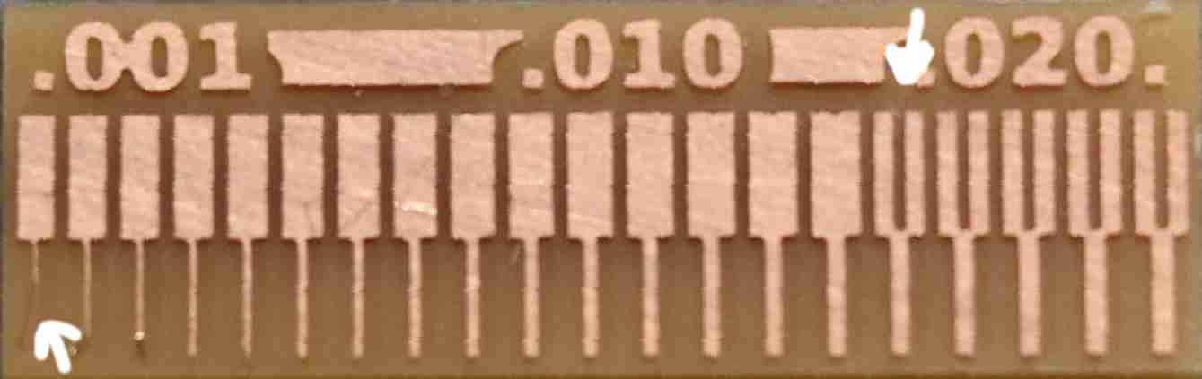
we can see the engine succeed to mill all the line but the thinnest (0.1 inch) was to fragile and we removed some copper with the fingers. and for the space, the thinnest we mill 1.9 inch
the different steps.
Preparing the milling
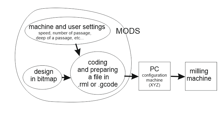
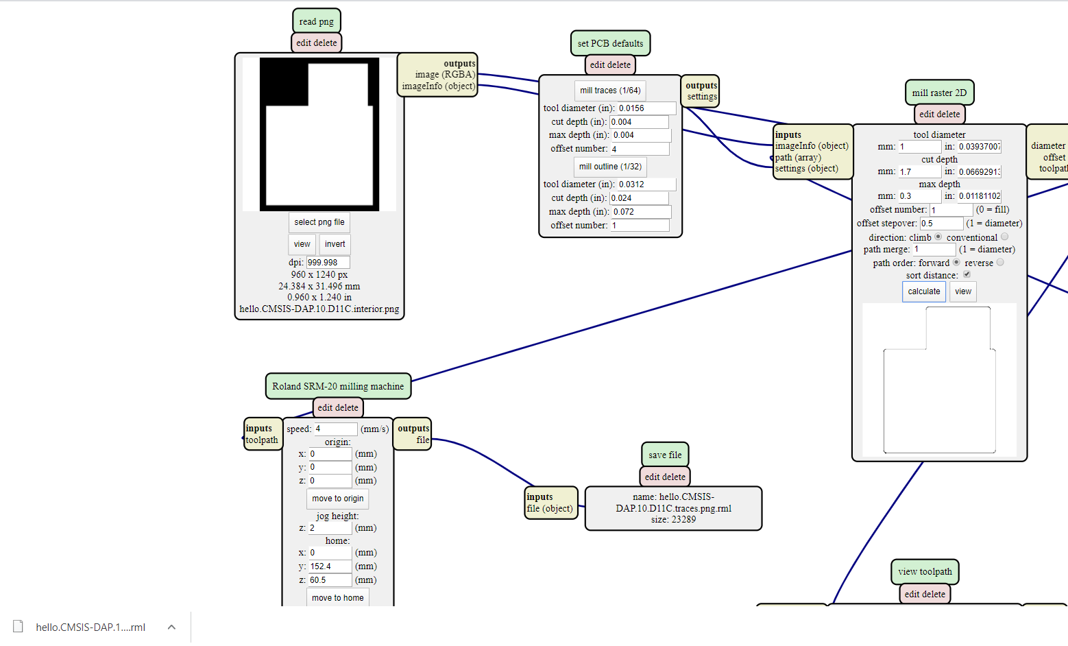
Mods
first, you have to choose the in-circuit programmer. For me, it’s CMSIS-DAP.10.D11C.
you need 2 .png files :
- for the trace (to remove the thin layer of copper)
- for the cut of the exterior (to detach the work from the entire board)
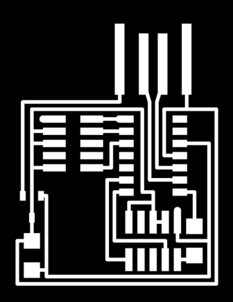

because it’s .png files, with a large zoom we see the limit of the fineness of the drawing up to the pixel limit.
2 files because you need to mill 2 times with different endmill and different deep and speed
to prepare the files, we use mods. Mods does not work with Edge. So we use Chrome.
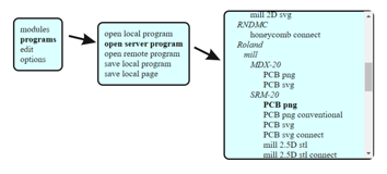
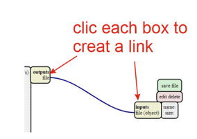
those first choices will open a more detailed screen
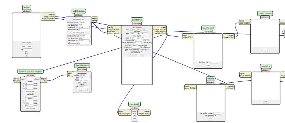
the different criteria to monitor
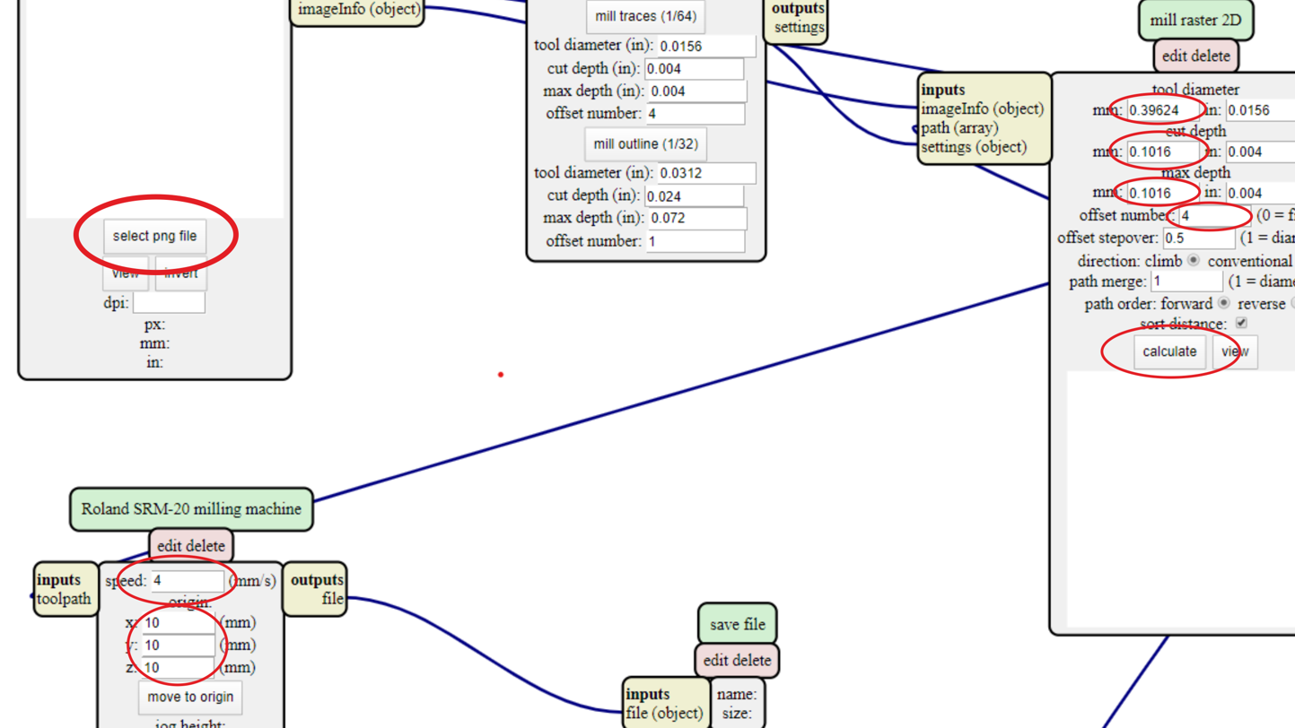
- A : size of the endmill
- B : deep to cut on each pass (never more than half size of the endmill)
- C : total of the deep to cut
- D : number of offset to enlarge the cut
- E : movement speed
- F : other elements. keep at 0
| trace | interior | |
|---|---|---|
| Endmill | 0,4 mm | 1 mm |
| total to cut | 0,1 mm | 1,7 mm |
| deep to cut each pass | 0,1 mm | 0,3 mm |
| number of offset | 4 | 1 |
| speed | 2 | 4 |
configuration for the trace file
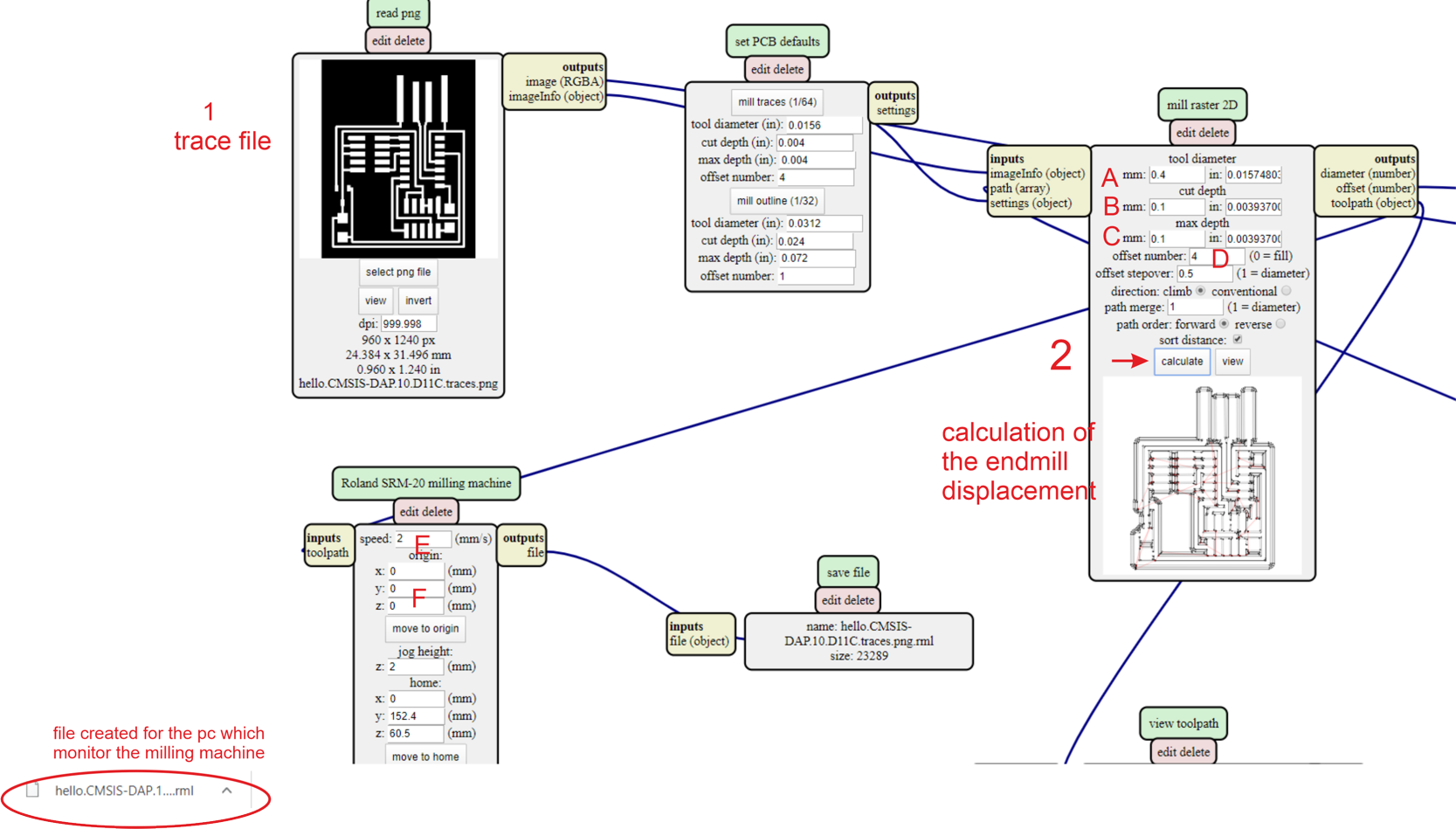
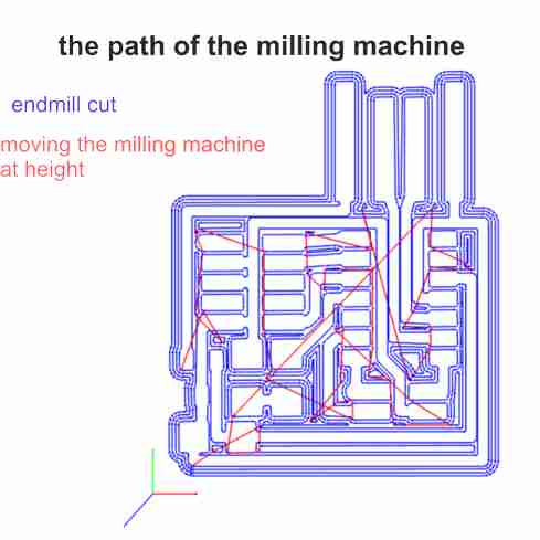
detail of the movement of the endmill
configuration for the interior file (cut of the piece from the board)
If no file is generated, there is a configuration problem
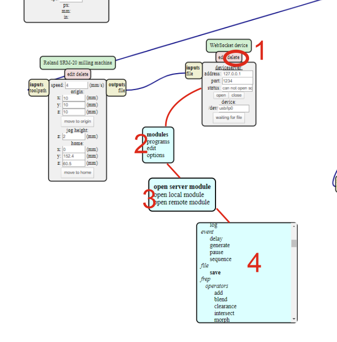
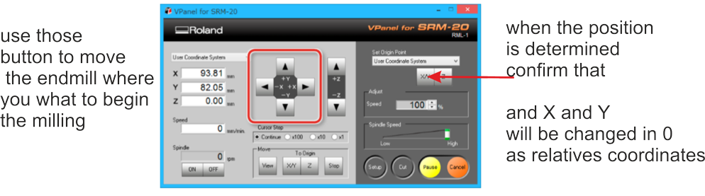
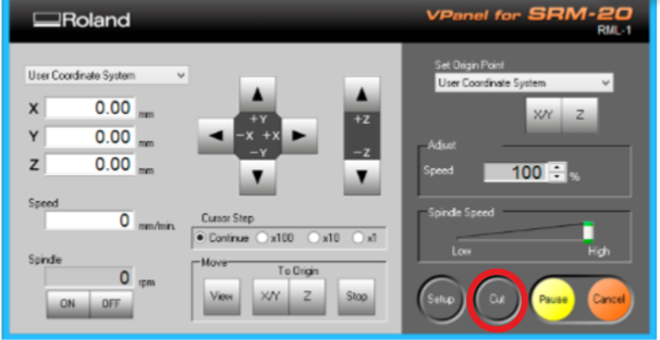
VPanel for SRM-20
on the computer linked to the milling machine, i use VPanel for SRM-20 for 2 main actions :
- adjusting the position of the endmill (x, y, z)
- outputing the files to the milling machine
The PCB Blanck
I used double side tape to fix the PCB blank to the sacrificial board. The tape must be laid precisely without bubbles. The PCB blank must be glued as strongly as possible and as horizontal as possible.
Technical data of our PCB FR-1 (FR = Flame retardant) : Bare copper card, Simple face, 150 x 100 x 1.6mm, 35μm, reference constructor
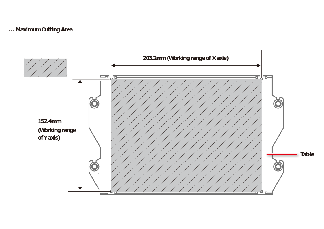
X Y of the milling machine.
Z of the milling machine.
.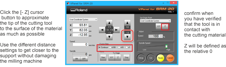
you can loose the set screw, and adjust the cutting tool so that its tip contacts the surface of the material, but you have to support lightly by hand not to drop a the endmill
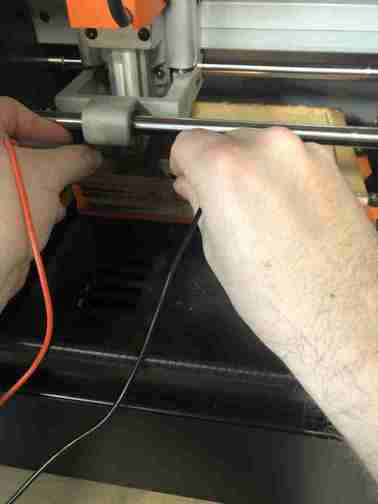
how to control the contact with the PCB ?
you can check the contact by checking the electric continuity
the setting of the control device
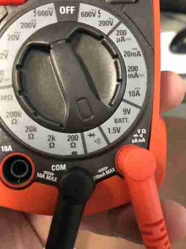
you touch the endmill and the PCB with each contact
if, because your Z setting of the endmill, the mill is outside of the limits of the machine, the endmill will rise and mill in the void
Beginning of the mill
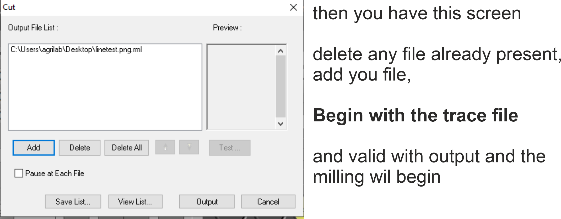
you begin by the trace file
and after the interior file to cut from PCB blank
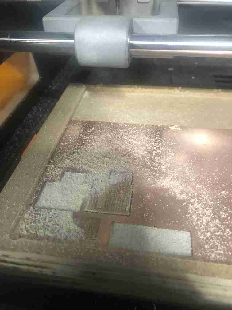
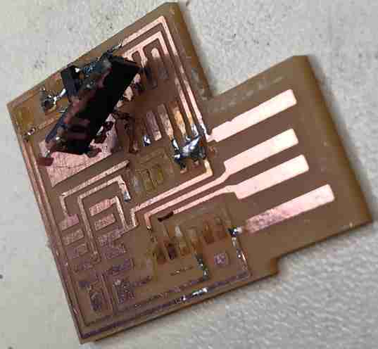
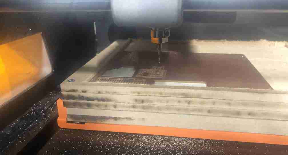
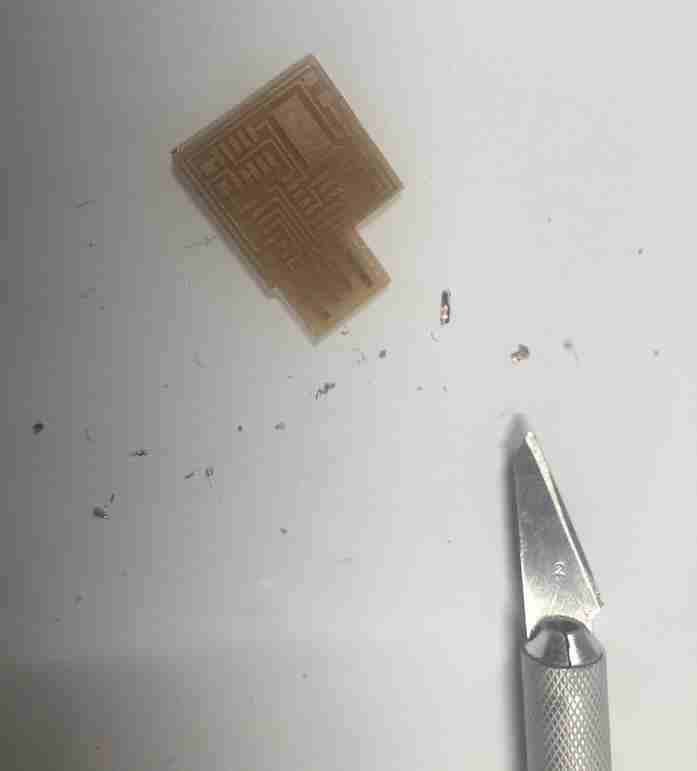
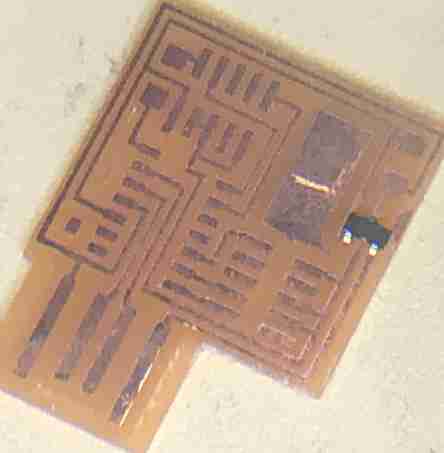
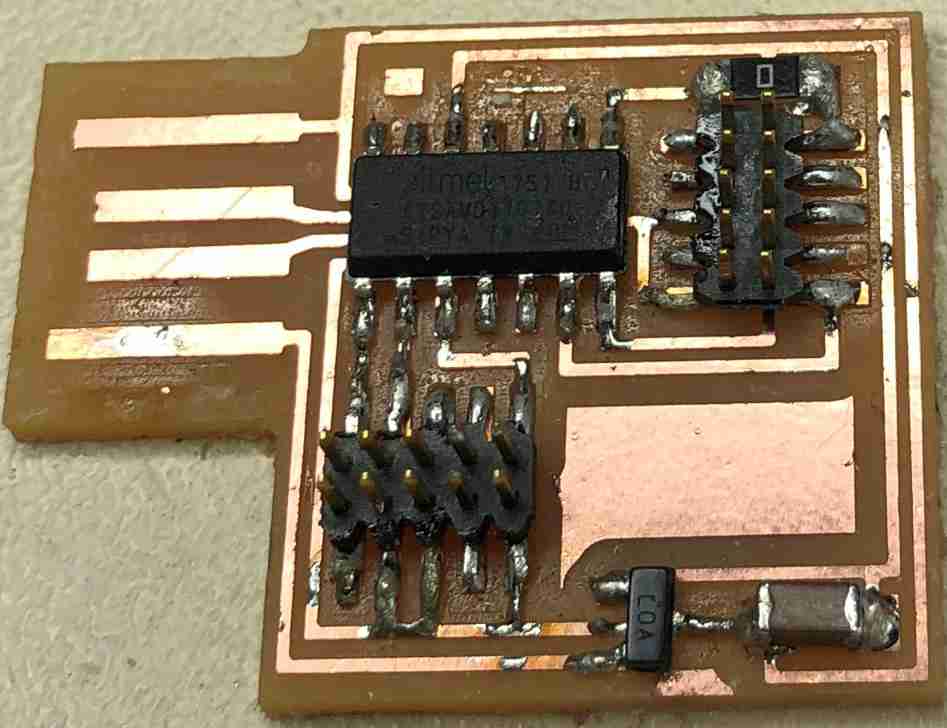
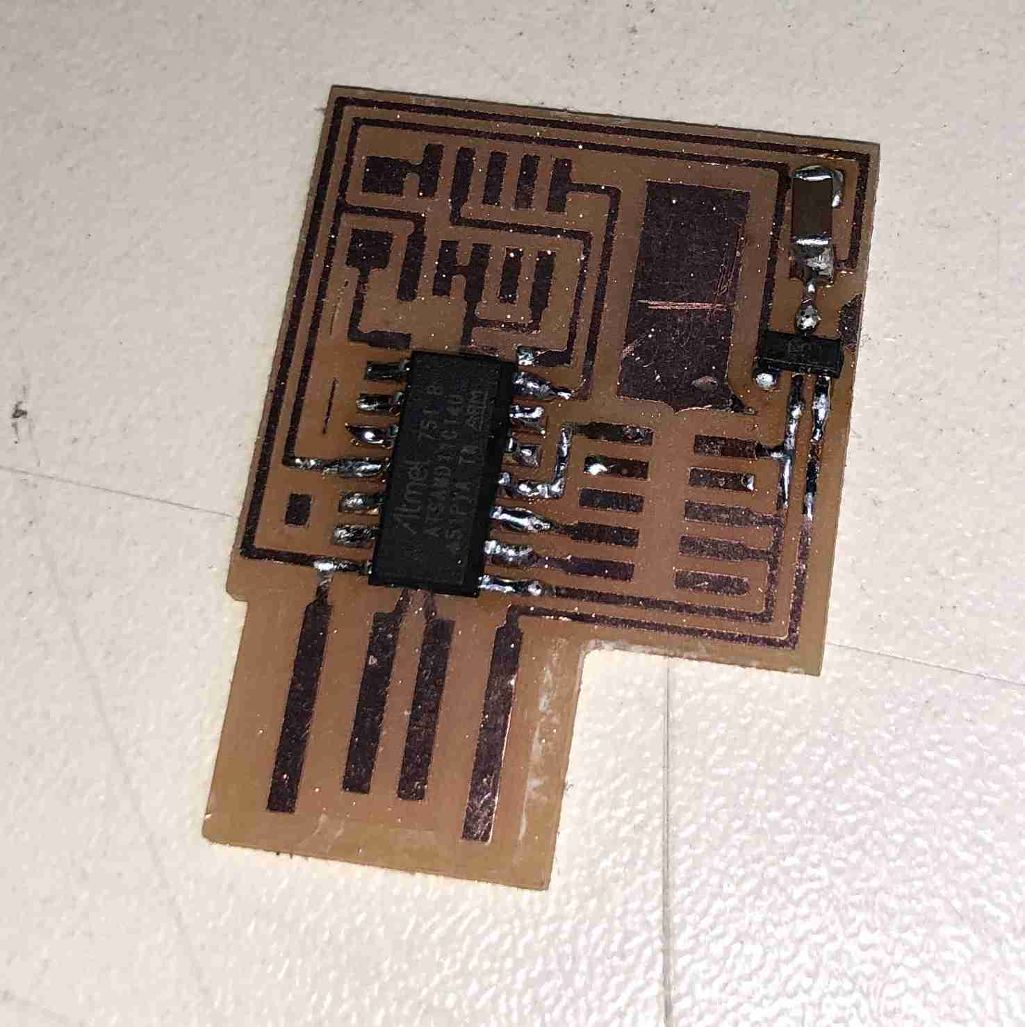
after melling, the piece is like that but not finished
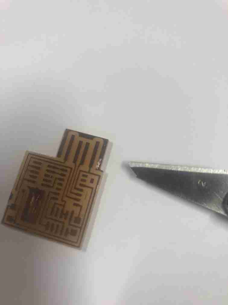
you may be obliged to manually remove some copper, to avoid shortcut
In circuit programmer
i have chosen to built a JTAG (ARM) in circuit programmer
Components
we have to select the components
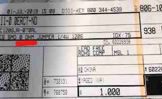
we have two informations :
we need
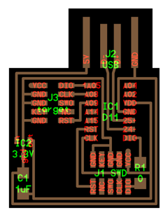
- 1 micro-controller (named IC1D11)
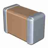
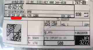
- 1 capacitor 1μF (named C1μF )
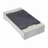
- 1 resistor 0 ohm (named R10)
- 2 connectors 10 pins (named J3 target and J1SWD)
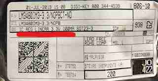
- 1 integrated circuit 3,3 v (tension regulator named IC2 3.3 v)
and in this file hello.CMSIS-DAP.10.D11C we can find another information
hello.CMSIS-DAP.10.D11C
SAMD11C CMSIS-DAP programmer
10-pin SWD header version
the components are
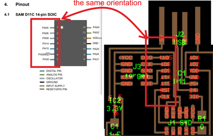
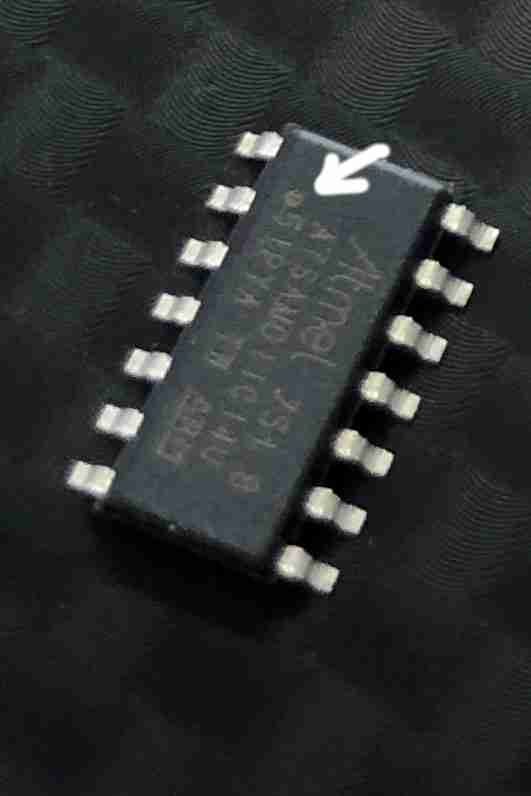
we need to determine the mounting direction of this component. it’s possible by comparing the documentation and the picture.
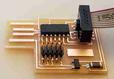
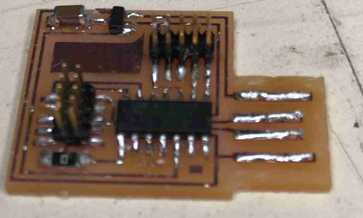
soldering
We are making a Surface Mount Soldering
one by one, you solder the components
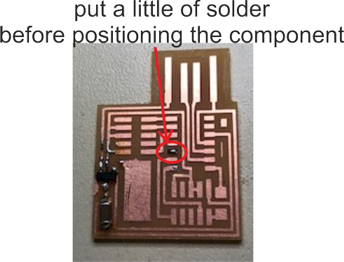
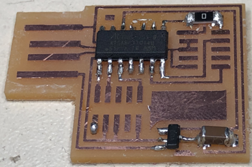
Solder must be added to the USB port to thicken the connectors and facilitate contact
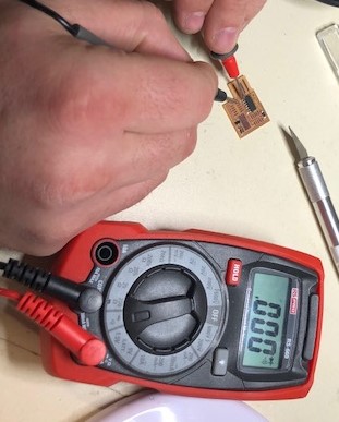
testing
test the continuity between solder and copper for each solder .
i will use the Atmel ICE to flash the boar with EDBG software
i need also to install atmel studio to install drivers.
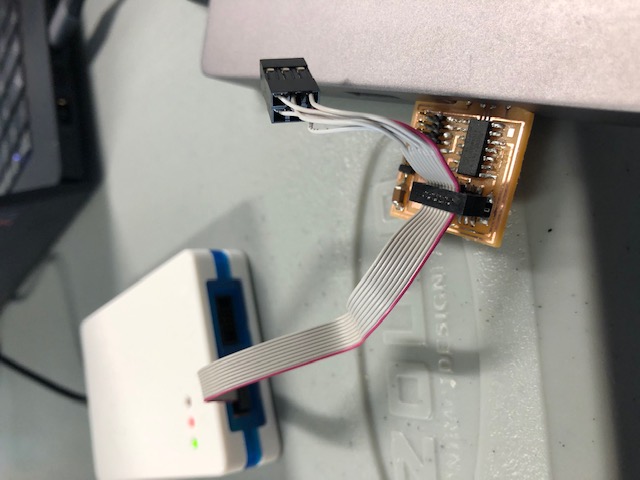
the board is plugged by the connector specified SWD on the design
in the directory where is installed atmel studio use the code
edbg -b -t samd11 -pv -f free_dap_d11c_mini.bin
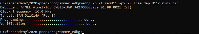
the syntax for EDBG is available at https://github.com/ataradov/edbg
Problems and mistakes
when you make a mistake in positioning the component
and when you try to repair and you remove the copper.