14 - Embedded Networking and Communications
Can You Hear Me? Do You Copy?
Tools & Assignment
 Updated for 2019 evaluation standards
Group assignment
- Send a message between two projects (assignments made by different students)
Individual assignment
- design, build, and connect wired or wireless node(s) with network or bus addresses
Learning outcomes
- Demonstrate workflows used in network design
- Implement and interpret networking protocols
Have you?
- Described your project using words/images/diagrams/schematic screenshots.
- Explained the programming process/es you used.
- Outlined problems and how you fixed them
- Included design files (or linked to where they are located) and original code
FAQ
Q: Can we use arduino/commercial boards for networking?
A: You can not use Arduino or similar commercial microcontroller boards. You can use a commercial wireless module in your own PCB.
For this week, you can use the original satcha-kit/fab-kit/fabduino.
Q: Must each board have a unique identity?
A: It does not have to be hard-coded but you must use some form of addressing.
2019
Originally I thought I could complete this week if any information was passed, by any means (via direct connection) to another board, short of using pigeons.
So I had hoped to use one Tx pin for the sending board & one Rx pin for the receiving board, but this cannot come to pass. This is sad indeed. I even wrote code to do this, so my boards are capable of it… I’ll probably use this for the final project since I get the feeling it runs faster and uses less resources (& pins) but I’m not sure that’s true.
The reason for this is that one of the requirements for this week is that we need to have addressing for communication.
As far as I know i2c, which uses 2 pins, is the least pin consuming option.
i2c
The basic premise with this protocol is that you use two wire, sometimes known as SDL & SDA, to communicate information in multi-master, multi-slave, networks. One of the lines is a clock, which means the system is synchronous.
Apart from this, what’s important is that hardware pins exist on the Attiny24/44/84, Attiny25/45/85 & AtMega328p that implement i2c.
These are named SDL & SDA on pinout diagrams found here.
Would you look at that, I used up those pins for CapSensing on my board…
That’s not very convenient. I hadn’t planned ahead because I was so certain Tx & Rx would have been fine, what to do?
i2c - The Hacker’s Way
Okay, so, after some searching for software based i2c, I came across around a half a dozen possibilities:
- SoftwareI2CLibrary
- SoftI2CMaster
- Arduino_Software_I2C_user_guide
- Sof-wire
-
… Wait a second, did I say half a dozen ? I meant to say a few dozen:
Anyways, I’ll spare you the pain, I like (& consider superior) todbot’s SoftI2CMaster, it’s just pure unadulterated bliss in terms of simplicity, and let me bask in that.
It doesn’t do slave mode though. I don’t care much for that since only one of my boards is pin-ly challenged. The TFT control board can use the hardware SDA/SCL pins and the standard Arduino Wire.
The only odd things about this is that the smaller board will be master… but who am I to judge?
Setting Up
Installation is as simple as it gets, we run
cd /path/to/arduino/libraries
git clone https://github.com/todbot/SoftI2CMaster.git
The alternative method is to download the repo as .zip file and add it through:
Sketch->Include Library->Add .zip Library
But that’s a whole 3(three) clicks instead of 2(two).
Anyhow, getting to the coding.
Coding
Credits go again to todbot for his examples
We have two programs, one for master, one for slave.
i2c_mastergoes to capsensing boardi2c_slavegoes to tft control board
i2c Master
We begin the code by defining the pins we will be reserving for the i2c communication & initialize a i2c object. This must be done first, so that the pins can be reserved, not clear on the details… documentation is scarce.
const byte sdaPin = 0;  // AtTiny44 pin 13
const byte sclPin = 1;  // AtTiny44 pin 12

#include "SoftI2CMaster.h"
SoftI2CMaster i2c = SoftI2CMaster();
Initialize a capSensing object, here again we can set whatever pin we went (in this case 8 as sender, 9 as sense).
#include <CapacitiveSensor.h>
CapacitiveSensor capSense(8,9);  // 8 (sender) is AtTiny44 pin 2, 9 (sense) is pin 3
We define / hardcode the address of the slave, we could scan… but since there is no command line output and only Serial output I’m not getting into that (since I’m sure debugging would be long and painful) when I can simply pre-define it.
byte slave_address = 10;
This sets-up the i2c object. In this case trueis for usePullups, meaning it sets the internal pull-up resistors.
void setup() {
  i2c.setPins(sclPin, sdaPin, true );
}
This is the main loop function that basically writes the data, since i2c can only send byte sized messages per write operation, I decided to pre-discretize the data into 1 & 0 to mean active and inactive sensors.
void loop() {
  float read_val = cap.capacitiveSensor(5); // Number of samples to take for capSensor (higher = more precise, lower = faster)

  if (read_val > 1900)
  {
    i2c.beginTransmission(slave_address);
    i2c.write(1);
    i2c.endTransmission();
  }
  else
  {
    i2c.beginTransmission(slave_address);
    i2c.write(0);
    i2c.endTransmission();
  }
  delay(50);
}
and that’s the master done. Simple right?
i2c Slave
With the slave things are smoother, since the Wire library is so well documented
First we include the libraries we need:
#include <Wire.h>
#define BAUD 9600
// I'm a slave
byte own_address = 10;
Extra) –
void setup() {
  Wire.begin(own_address);       // join i2c bus with address #10
  Wire.onReceive(receiveEvent); // register event
  Serial.begin(BAUD);           // start serial for output
}
void loop() {
  delay(50);
}
void receiveEvent(int howMany) {
  while (1 < Wire.available()) { // loop through all but the last
    char c = Wire.read(); // receive byte as a character
    Serial.print(c);         // print the character
  }
}
Hero
This is how the result looks:
Layout of Boards
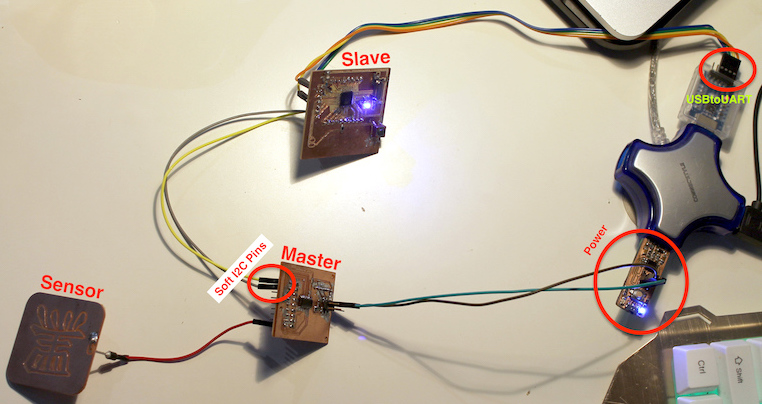
Hero
Extra - Serial Code
I won’t comment on it on here for now (unless asked to) but while I worked for this week I also made a serial communication code which, as I explained earlier I couldn’t use for this week because of the requirements.
I’ll add it because I’m proud of it :) It only uses one pin on the capSense board with SendOnlySerial which is great, since we limit resource usage.
However this is basically and edited version of cap_over_serial_v1 from week11.
Final thoughts
This week seems short but it was the hardest and longest for me to do, I tried many different software options, which I didn’t document because I was in a rush to finish everything. So what you see is a polished final version.
In fact todbots repo is pretty obscure, with only his example code to understand how his entire library works. I only came across the list of all those libraries when I was writing up this page, finding it was not straight forward.