- Salem AlMarri
- Super FabLab UAE
- Last Reviewed on 29/5/2019
- Last Modified by Salem AlMarri
Introduction
In this week we are designing the mechanical parts of our CNC machine which is designed to cut textiles, specifically Kandoora, UAE's national dress. Although there are ready made Kandooras in the market, most of the people feel more comfortable making their own custom-sized Kandooras in tailor shops. Tailor shops usually take measures to sew a custom Kandoora. The issue is that the process is prone to errors, either from the measures taken, or the tailor who is sewing the Kandoora. Upon receiving a batch of Kandooras, Kandooras usually vary in size slightly, and sometimes unfortunately the error is bigger than that, a pocket might be smaller, the Kandoora length might be longer or shorter etc. The Kandoora Cutting Machine is promised to solve this issue with the consistency and precision of the CNC technology.
Stepper Motor Bracket - Fusion 360
To design a bracket, it is important to specify the motor type as each motor has its own dimension, hole positioning and etc. The motor used for the Kandoora Cutting Machine is a NEMA 23 stepper motor of a 57x57 dimension.
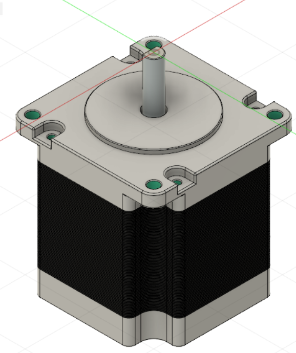
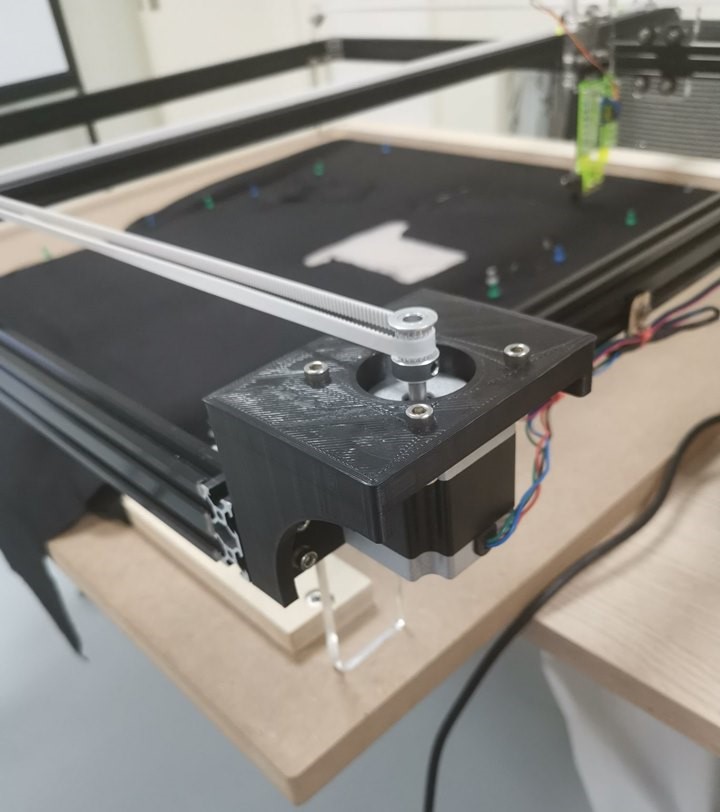
The bracket design would fit the stepper motor and allow it to mount on the aluminium profile along with the other components that make up the CNC machine.
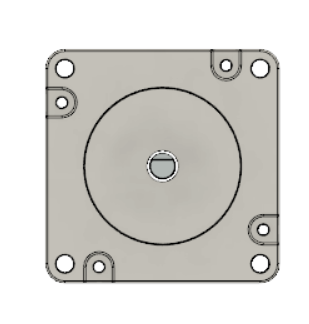
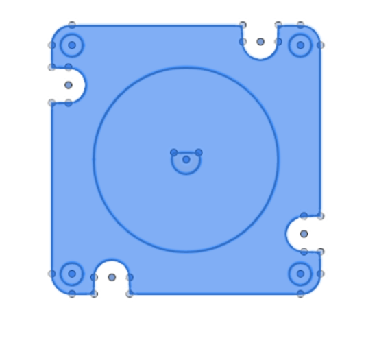
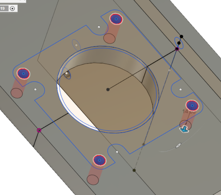
Creating a sketch over this side of the NEMA 23 stepper motor ensures designing the bracket with similar dimensions, afterwards the diameter's dimension can be increased to account for 3D material shrinkage and allow a screw to be used for the motor and the bracket.
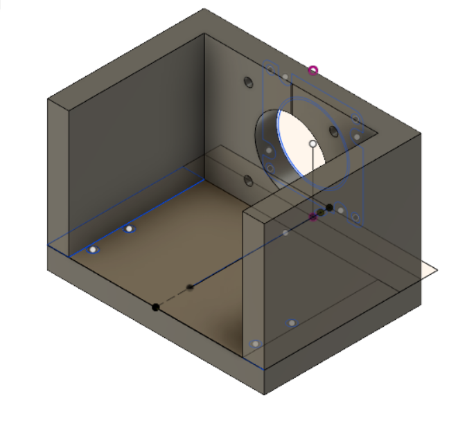
The stepper motor features are then added to an L-shaped bracket design which is designed according to the dimension of the aluminium bracket.
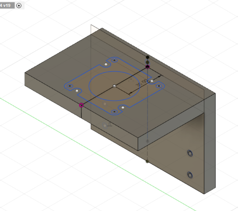
In the step, the extrusion to cut existing material to account for the motor's screw holes. The screw holes of NEMA23 stepper motor are of 5mm, in this design the holes were adjusted to 5.5mm to account for 3D printed material shrinkage which is measured previously to be between 0.2-0.4mm.
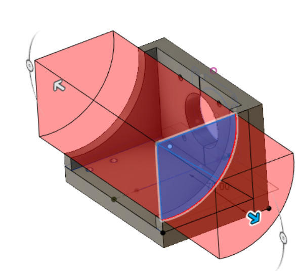
The L-shaped bracket is now supported by two new wall supports, the brackcet now is no longer L-shaped. The purpose is to add more support to the bracket to both hold the stepper motor and be mounted on the aluminium bracket. A curved sketch is then added to the bracket walls which is then cut using extrusion to reduce printing time and add more efficiency to the structure.
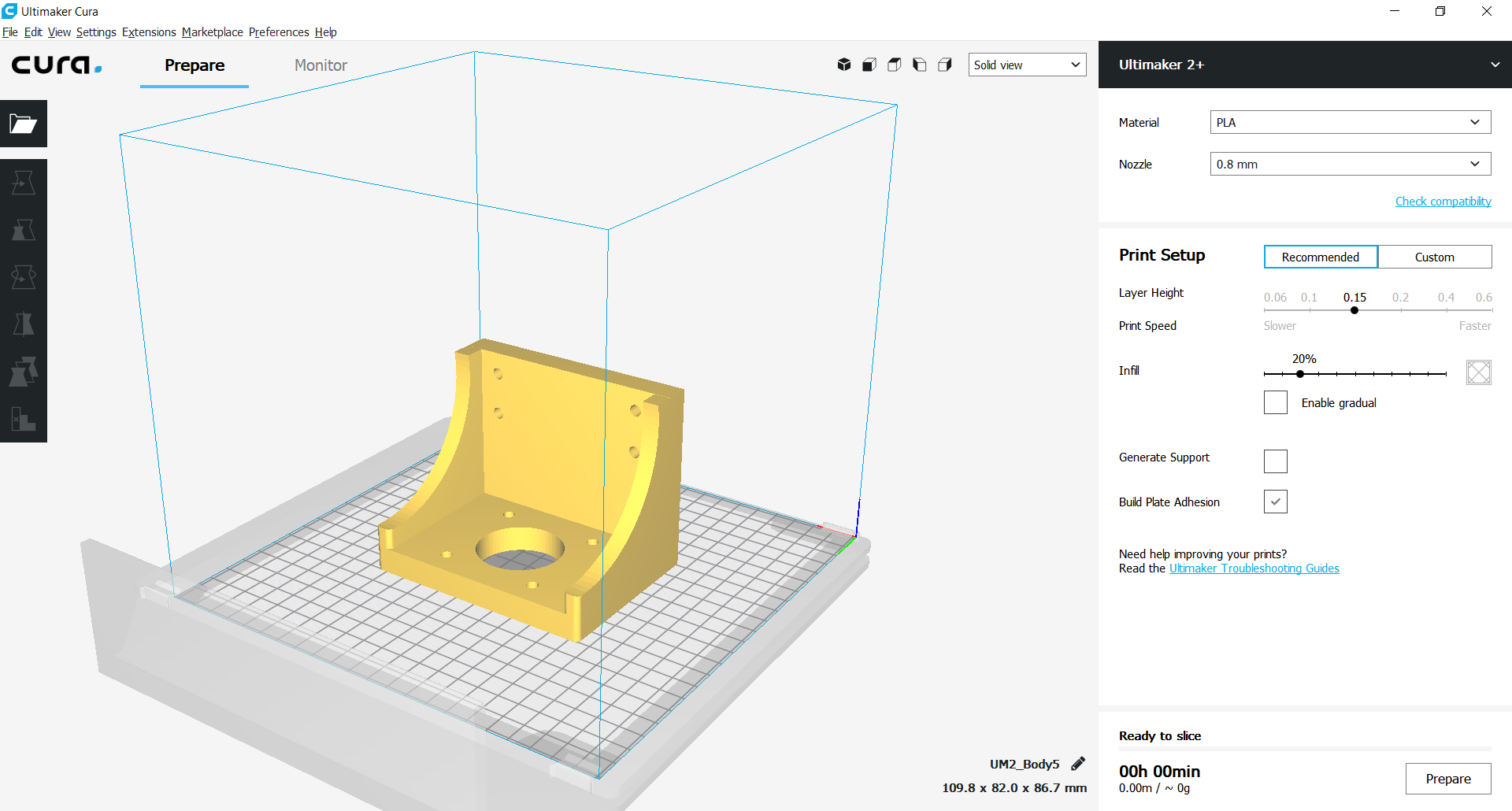
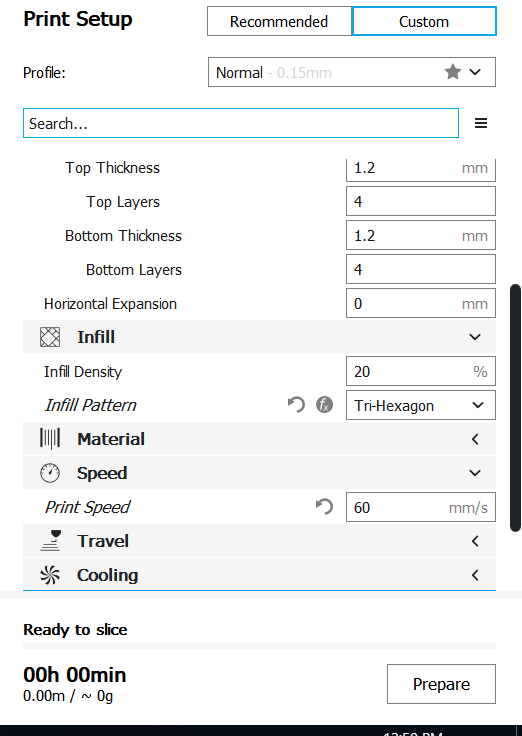
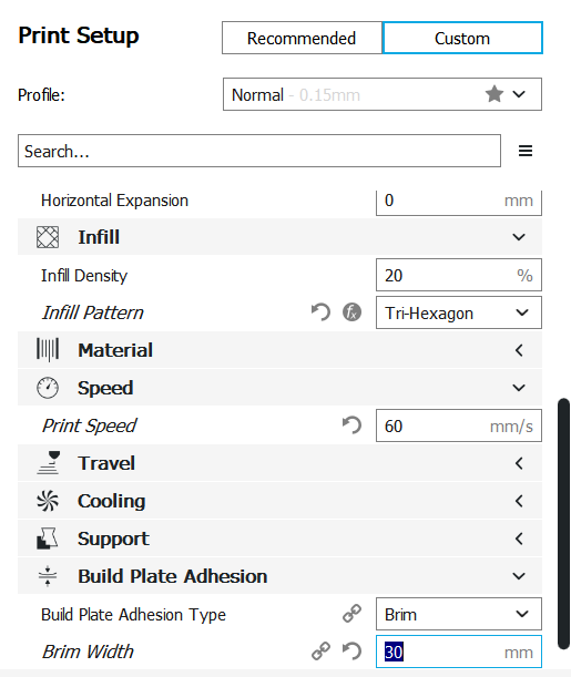
Stepper Motor Bracket - Ultimaker CURA - Ultimaker 2+
The design STL file was exported to CURA, the 3D printer was first chosen with PLA material and 0.8mm nozzle. The print setup was custom. The thickness, infill, infill pattern, print speed etc were all changed
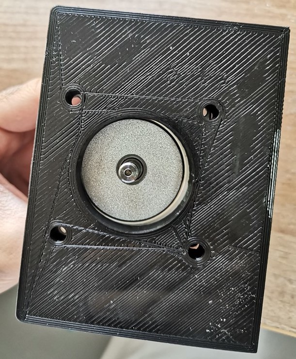
3D Printed Results
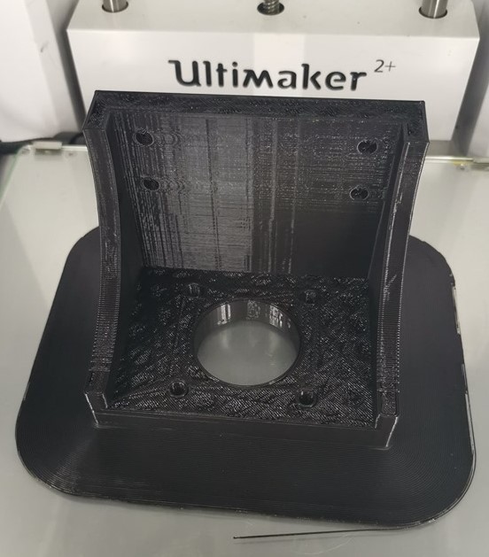
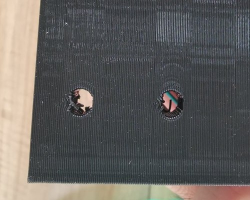
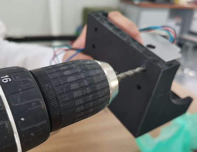
It was difficult to insert the screws into the holes of the 3D printed bracket. Using a drill, the extra filament which is obstructing the holes are removed.