Electronics Production
- Salem AlMarri
- Super FabLab UAE
- Last Reviewed on 18/2/2019
- Last Modified by Salem AlMarri
Introduction
This should be my most interesting week. I graduated as an Electronics Engineer, but never got the chance to learn how to produce circuit-boards. Now using Roland SRM-20 we will learn how to mill and cut to produce the base of circuit-boards that would then have components soldered onto, the circuit-board would then be programmed.
Preparing Files for PCB Fabrication
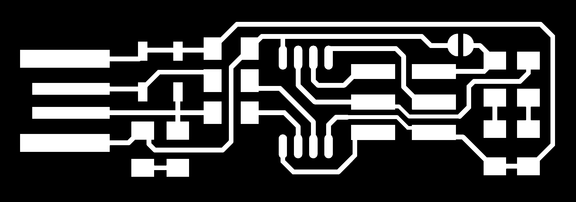
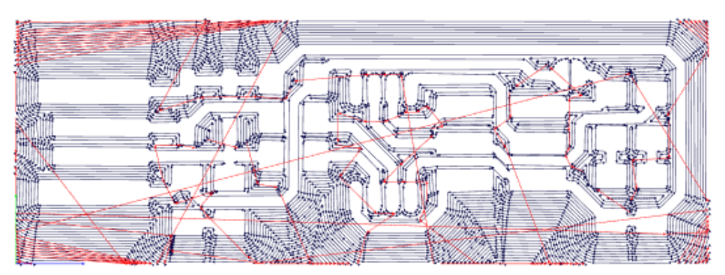
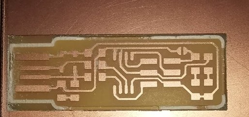
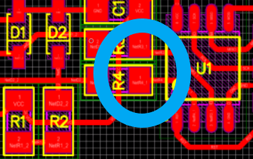
The first step would be to mill traces on the PCB to electrically connect various connectors and components to each other. Using Roland SRM-20 and a 1/64 milling bit, we will produce the following traces on the circuit-board.
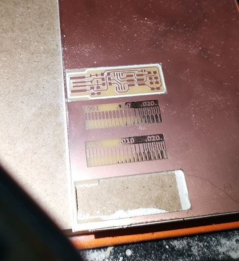
The second step is to cut the board according to the outline.

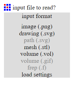
The third step would be to import each file from step one and step two seperately to fabmodules.org website to convert each file to the desired format required by the machine.
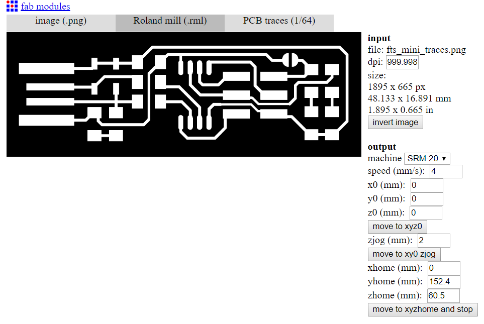
1. Choose Input File, (in our case image (.png)):
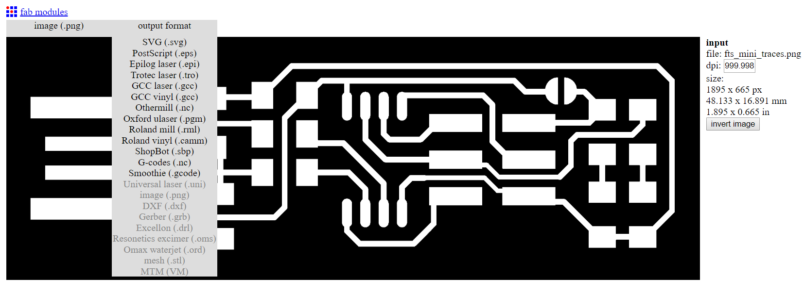
2. Choose Output Format, (in our case Roland Mill (.rml)):
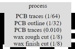
3. Choose Process (in our case first traces (1/64) and then PCB outline (1/32):
4. Change Output Parameters (x0, y0, and z0) to (mm) 0:
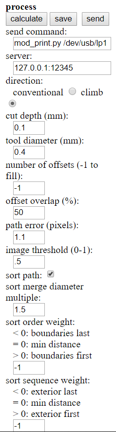
6. Number of offsets to (-1), Press Calculate: to remove the extra copper.
7. Calculated Results with Number of Offsets (4)
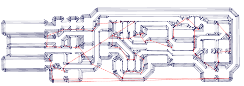
8. Calculated Results with Number of Offsets (-1)
Milling Traces - PCB Fabrication
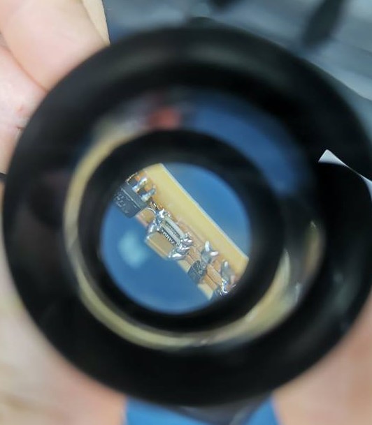
Checking the Milling Bit under microscope
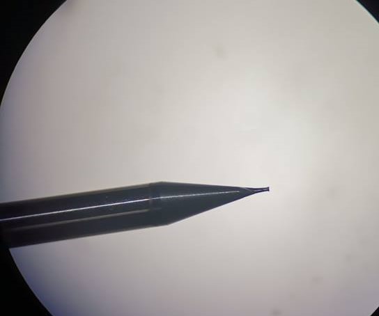
Before starting the milling process, check if the mill bit is (1/64) and level Z-axis.
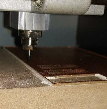
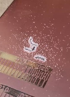
Pause and check if the milling process is correct.
Cutting - PCB Fabrication
Change the milling bit to (1/32) for cutting. If the Z-Axis was not leveled correctly then we will not be able to move the piece from the copper plate. In my case I had to level the Z-Axis twice.
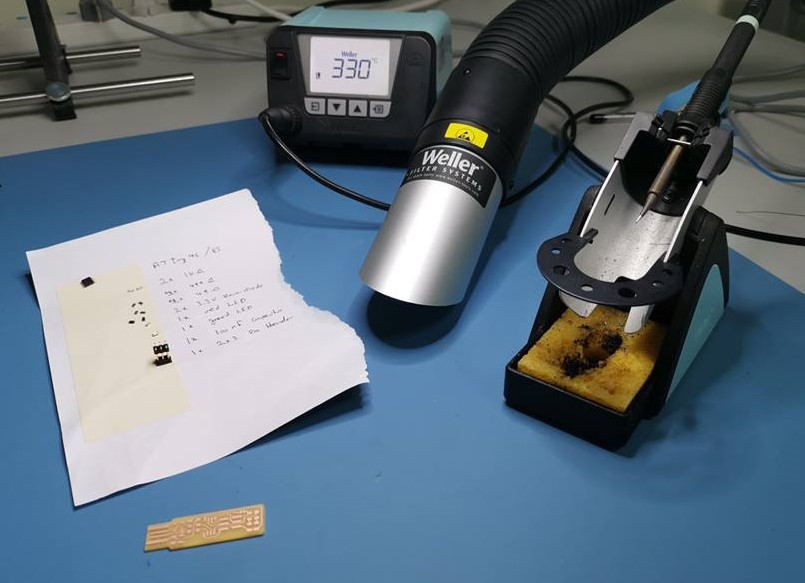
Soldering - PCB Fabrication
Prepare all the components based on the following guide.
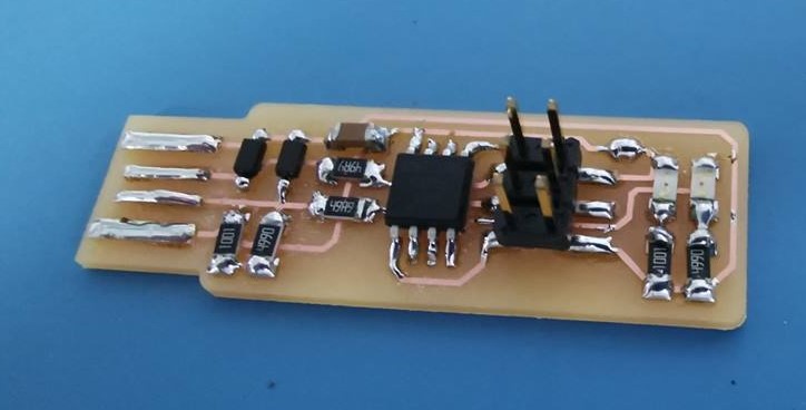
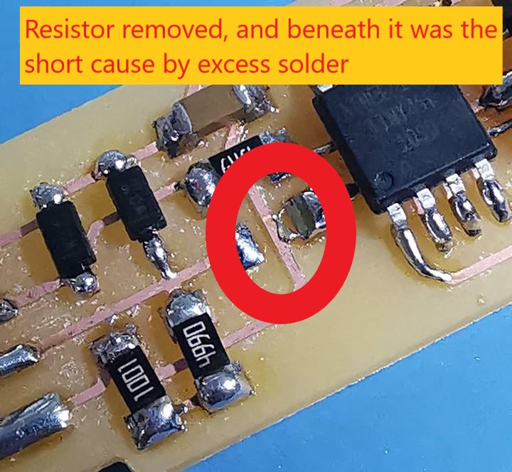
Using the multimeter to check the soldering. Unfortunately two traces were shorted due to excess solder used.
Programming - PCB Fabrication
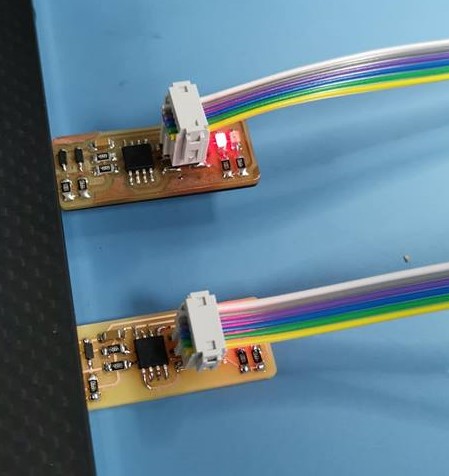
Rainbow cable, checking the one available in our lab, it had 7 wires. A wire was removed to make it 6 in order to make it fit in the connector.
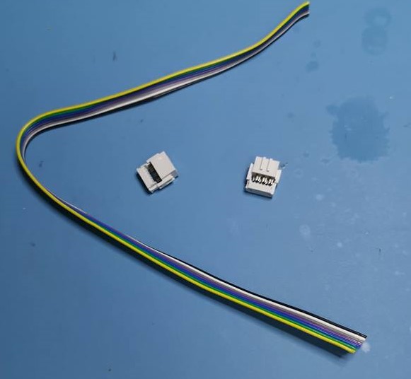
The connector must have the same orientation on both ends of the cable.
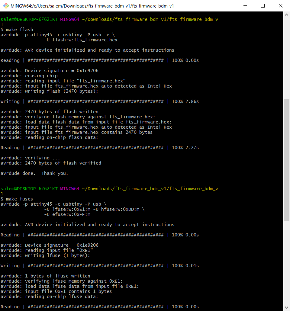
Following steps on the guide we must download the firmware then using Git we use the following commands:
- make flash
- make fuses
- make rstdisbl
Preliminary steps before starting to program the FABTinyISP is to check that GNUWin32, avrdude, and avr8_gnu_toolchain recognized by the path.
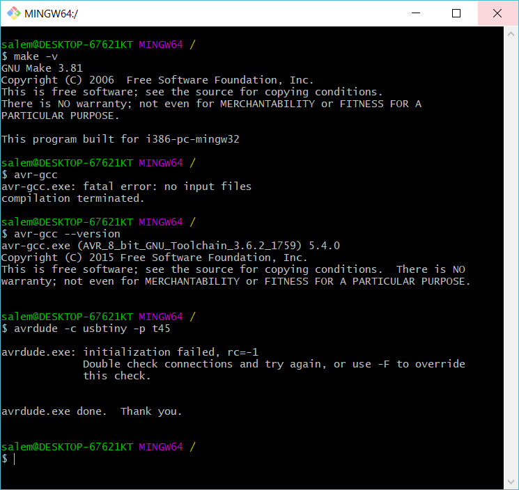
Using the previous commands in Git, results:
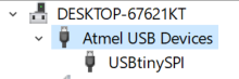
The USBTinyISP now can be recognized by the PC from Device Manager in a category different than the Universal Serial Bus: