Computer-Aided Design
- Salem AlMarri
- Super FabLab UAE
- Last Reviewed on 19/2/2019
- Last Modified by Salem AlMarri
Introduction
In this week we are introduced to various tools used to present models in 2D, 3D and etc. Each presented tool was used in a certain industry, for example CAD tools like LibreCAD, Fusion360 is mostly used in our industries pertaining to making, engineering, industrial etc. Tools like CorelDraw and Rhino3D were used in industries pertaining to art, design, etc. I, myself thought that I already knew everything related to CAD as I have been working on it for the past 3 years. I was surprised to realize I was missing a tool like CorelDRAW that would enable me to produce artistic designs for my project. Also, I was surprised to learn additional techniques like parametric design in CAD. I was just baffled with the amount of information I was missing out.
2D Design with CorelDRAW
CorelDRAW is mostly found in the professional world as a vector graphics editor used to design business cards, brochures, etc. The tool is also able to transform any picture into vector, allowing it to be resized without becoming pixelated, CorelDraw.
For the 2D assignment I have challenged to use CorelDRAW even though I was able to use other softwares like paint or power-point presentation to design a 2D perspective of my project based on my previous sketch. I would usually use those softwares to customize various dimensions on vector icon files to make up a representation of an idea, and for that I used to spend more time looking for certain formats that CorelDRAW can generate from any picture.
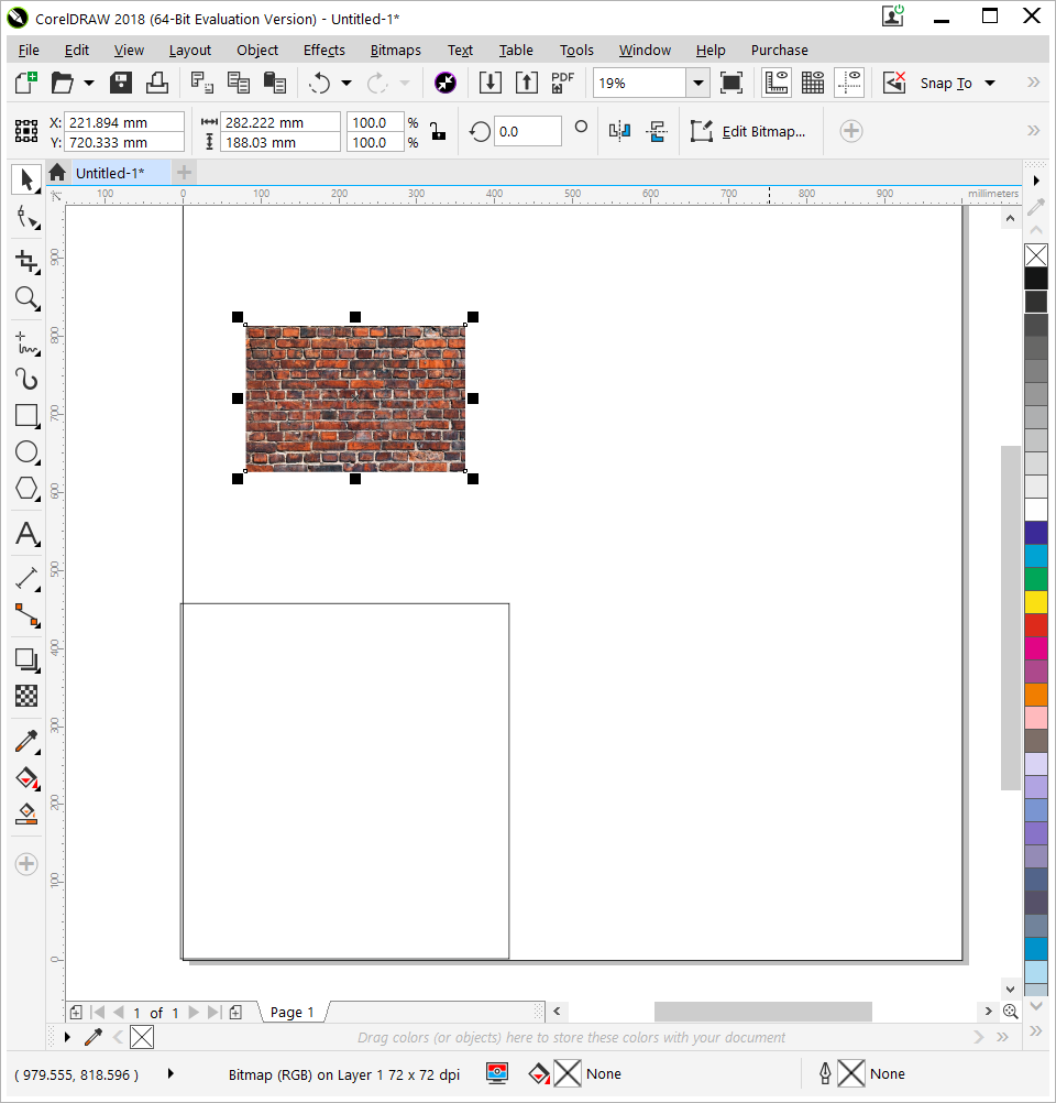
In the Below Image:
A real life picture was obtained from Google was imported to CorelDRAW by drag and drop.
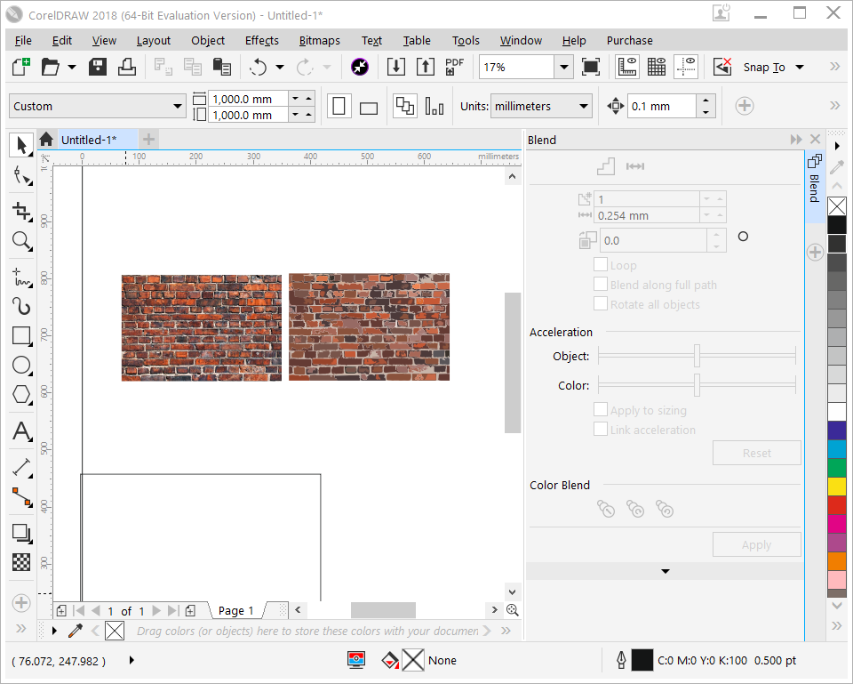
Bitmap Trace Feature (Below Image):
A vector image was generated using a feature called Bitmap Trace used to vectorize any 2D image. The image on the right is the vector format of the wall on the left. The vectorized image may be altered without showing any pixelation. The graphic formats of a vector image can be SVG, EPS, or even PDF.
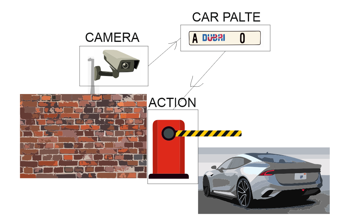
2D Presentation of the Project:
3D Design with Fusion360
Fusion 360 software from AutoDesk is the first software to be used for the entire product development process as it combines 2D CAD, 3D CAD, CAM, and CAE. It is also a cloud-based platform used to design, test and fabricate. As for myself, I am more used to Inventor, another software from AutoDesk. Since I was encourage by my mentors and FAB Academy to learn to use different types of softwares, and so I decided to use Fusion360.
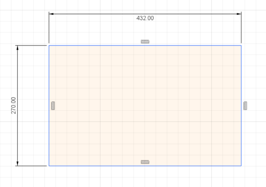
Start of 2D Design of Project Box
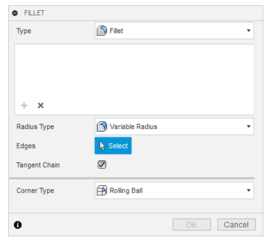
The design is based on a rectangular sketch. Another rectangular sketch was added within the design to be extruded a hollow feature. Only the area between two rectangle sketches will be extruded into a 3D material of X thickness. Two lines on horizontal and vertical axis connect to sketches to maintain centralized positioning. In addition, to make the box look better, sharp corners were filleted into a rounded shape.
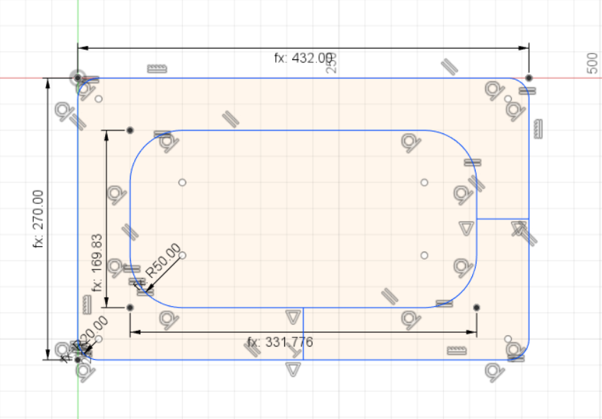
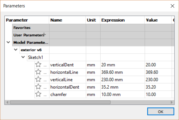
Initial Attempt with Parametric Design:
Now since I have designed the basic dimensions, I was curious to try parametric design. Parametric design would allow the 2D parameters of the project to be manipulated using less parameters. It would require understanding and programming each parameter based on its relationship with other parameters.
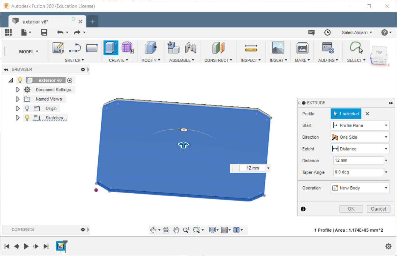
Transforming 2D Sketch into 3D (Extrusion):
In this step, the sketch was extruded to be a 3D object. In terms of parametric design, the thickness would be altered depending on the thickness of the material available without requiring effort to redesign everything from scratch as all limitations would be accounted for automatically in the algorithm developed.
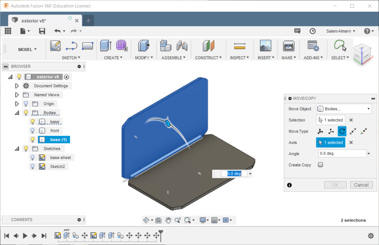
3D Object was Replicated as a New Object:
As part of rapidly designing the project and using even more features from the software, it was not required to make a new sketch all over again since there will 4 different sides with almost similar dimension. In this step, the new body was rotated with respect to the previous body to be positioned perpendicularly.
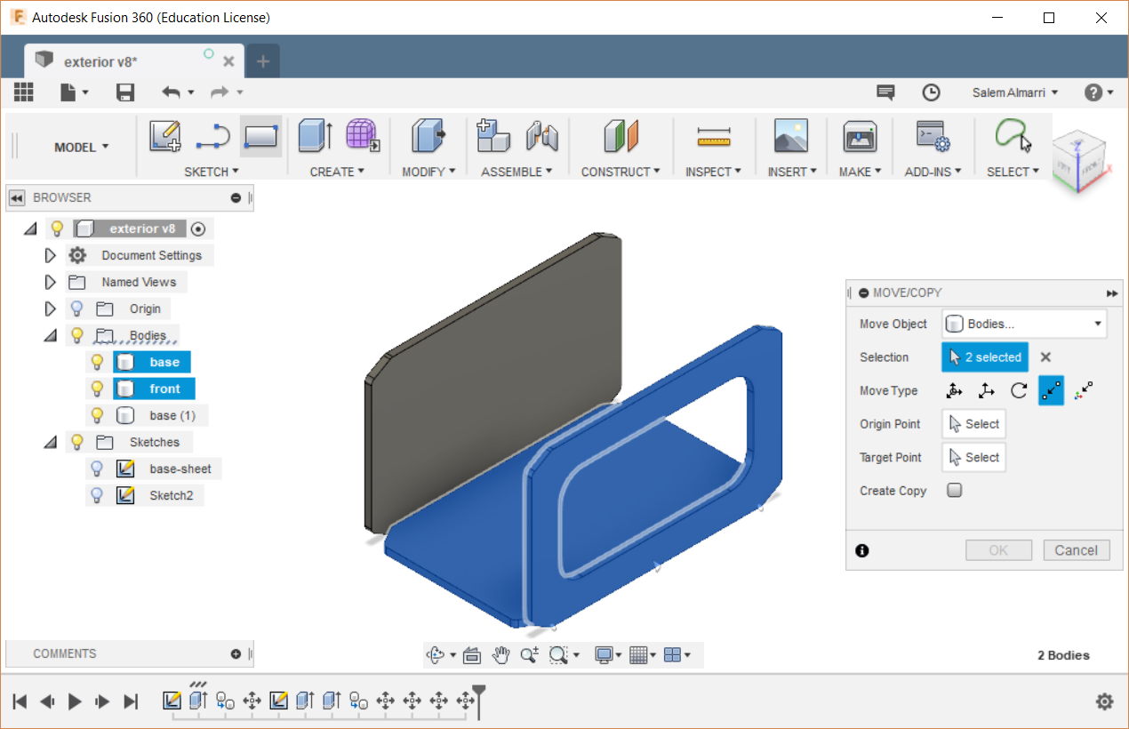
3D Object was Replicated as a New Object:
As we can see now we have three different bodies, the third new body has the same dimensions with one difference. The difference is that the middle part of it was not extruded, leaving an open whole in the structure. This was used by going back to the first sketch made but it belonged to the third body, and a drawing was placed in the middle were the extrusion excluded the drawing.
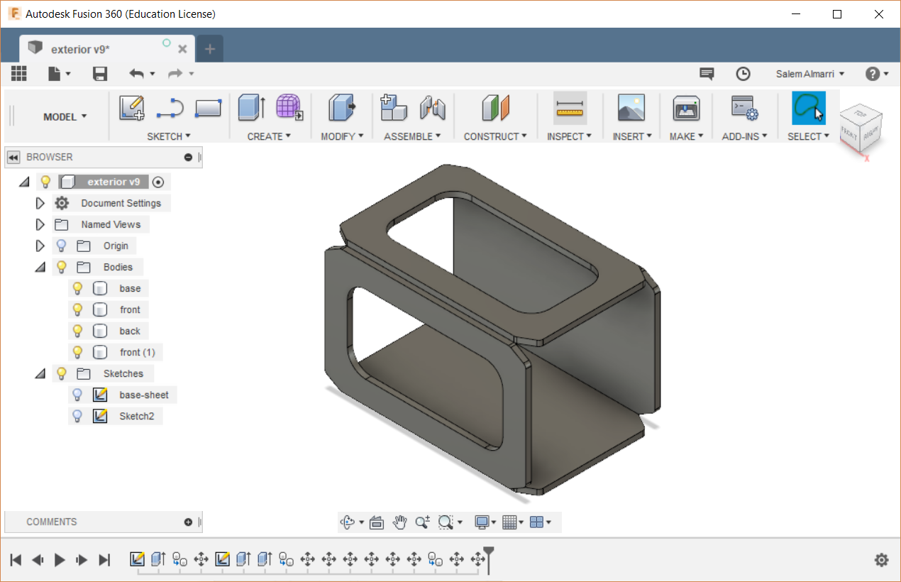
The Project Box:
Although the box is missing two sides and means to joining all the parts together. The two sides would be designed and added within this week, and next week we will learn about joints, thats when all sides of the project would be joined together.
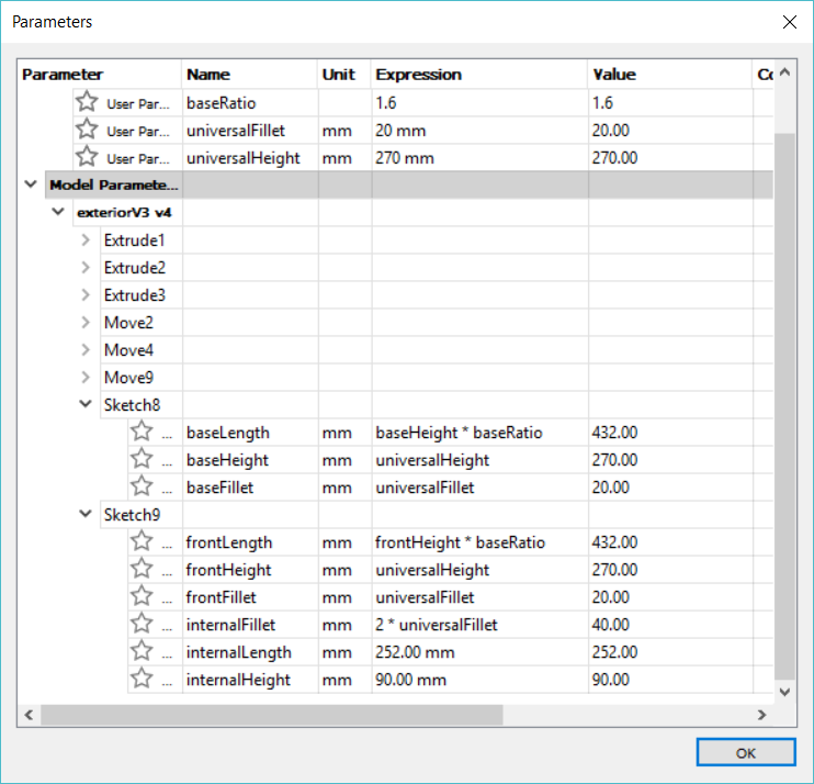
Parametric Redesign
With the help and support of my mentors during the support hours, I was able to have a fully functional parametric design for my project box with its current state. The parametric design now have two control parameters which are universalHeight and universal Fillet, any changes to these two parameters would have a controlled manipulation to the project while fully maintaining all the relationships between the parameters.