Electronics Design
- Salem AlMarri
- Super FabLab UAE
- Last Reviewed on 05/3/2019
- Last Modified by Salem AlMarri
Introduction
This week's assignment is to design, fabricate, solder and program an ATtiny44 based board (echo hello-world board). It is also required to add an LED and a button to the board.
ATtiny44
The ATtiny44 is a high performance low power 8-bit microcontroller. A circuit board based on this microcontroller will be designed and fabricated, along with an input and an output, a button and an LED. When designing circuit boards, it is important to always refer to datasheets of components that would be making up this board, in this case, the most important datasheet is that of the ATtiny44.
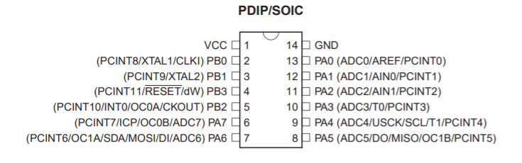
The above screenshot is taken from the datasheet, at this stage it is important to understand the layout of the microcontroller packaging. Pins such as VCC and ground must connected to components such as the button and LED correctly, otherwise the electrons flow may be shorted, or connected incorrectly would could lead to permanent damage to board's components.
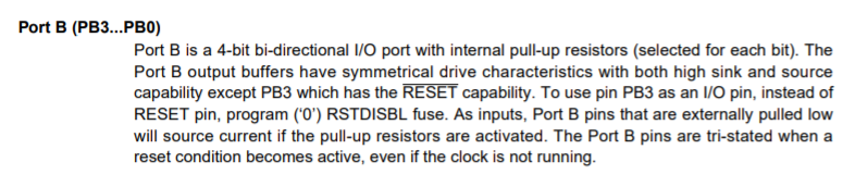
To make use of the button as an input, in the design one end of the button should connect with the VCC, and the other end should be connected to a pin which could be programmed to be an input pin, once the button is pressed, a high level signal would reach the pin, and as per the program, this input signal is enough to control output components state, turning the LED on or off, or changing the blinking rate. Below is another screenshot of port B.
The LED cannot be powered directly using the VCC's 5 volts, this would burn the LED and render it useless for any future use. An LED is a diode and a diode often requires a voltage of 1.8V ~ 3.3V to operate. In our case we were required to use resistors to drop the 5V to 3.3V. An LED would often consume a current of 20mA, the equation used to determine the resistance required is as follows:
V = I X R
5/0.02 = R
R = 250 Ohms
The resistance required is at least 250 Ohms or higher. Depending on what was available in the lab's inventory, the nearest resistance value was 499 Ohms and it was more than sufficient to ensure that the voltage is dropped as required.
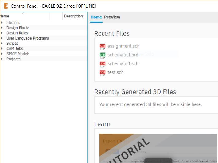
EAGLE
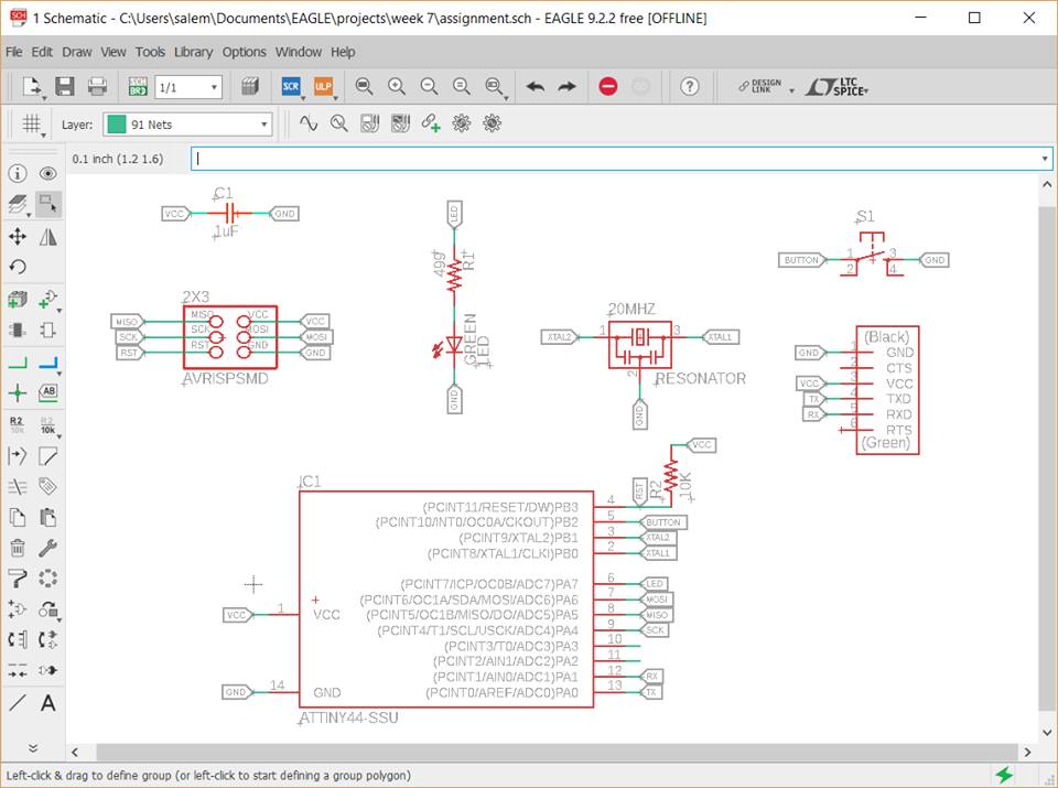
Using EAGLE program, a schematic for echo hello-world board (based on ATtiny44) will be made. More information on the board are found in here, echo hello-world board. A similar design and two additional components will make up the new schematic.
To make the schematic we require to add FAB Academy's library from the following link, where libraries leads to this address. The FAB Library must be downloaded and added to EAGLE's root folder ./document/EAGLE/libraries/FAB
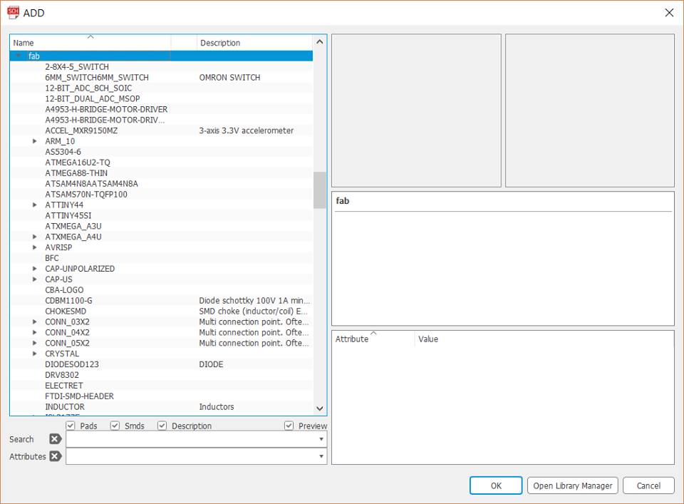
The components shall then be obtained from FAB library. Components such as ATtiny44, resonator, button, resistor, capacitor, LED, AVRISP, FTDI connector. By clicking "add part" components can be added, and for each component connectors must be added "Net", and then "Name" from the left window as well must be chosen first and then then the desired line can be named with the relevant "Label".
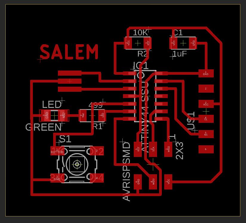
The board now is ready to be exported from schematic to board through EAGLE (top window). Once exported.
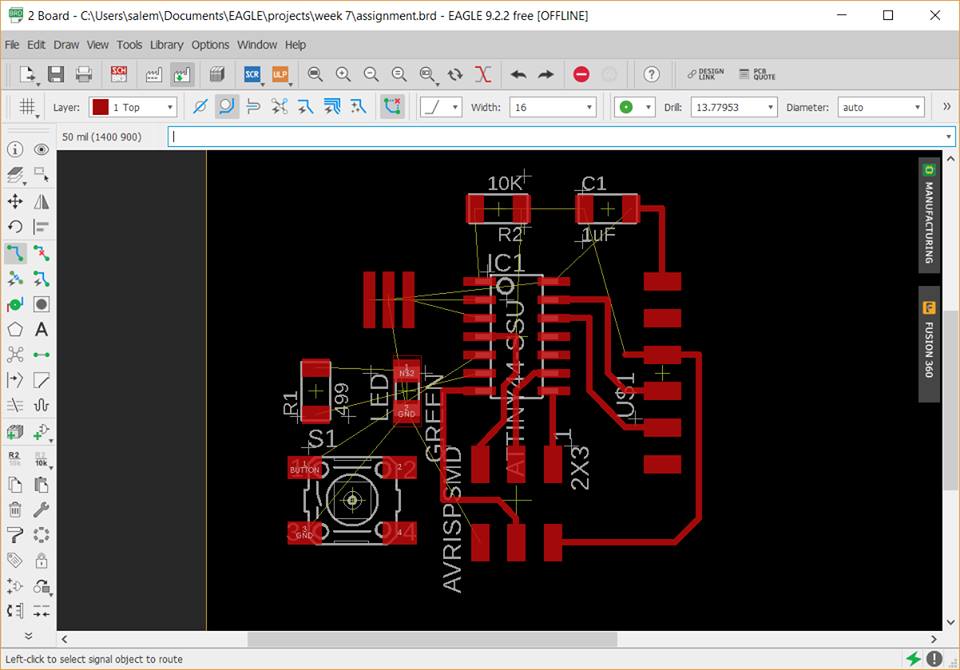
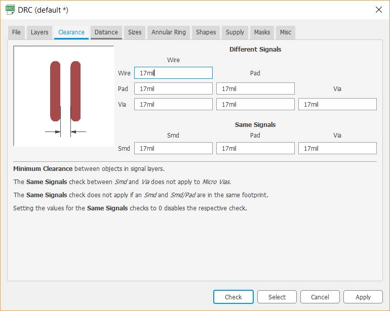
Before routing the components each with its respective label. Through design rule check, an important parameter must be set with respect to the milling bit that would later be used in the fabrication process. (Milling bit is 16 and clearance is 17)
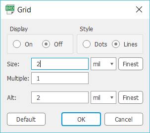
On grid, decreasing the number of size and alt allows to move routed lines, components in a finer manner as they snip to a smaller area rather than a big square. (Allowing easier correction, smoother lines and object placement)
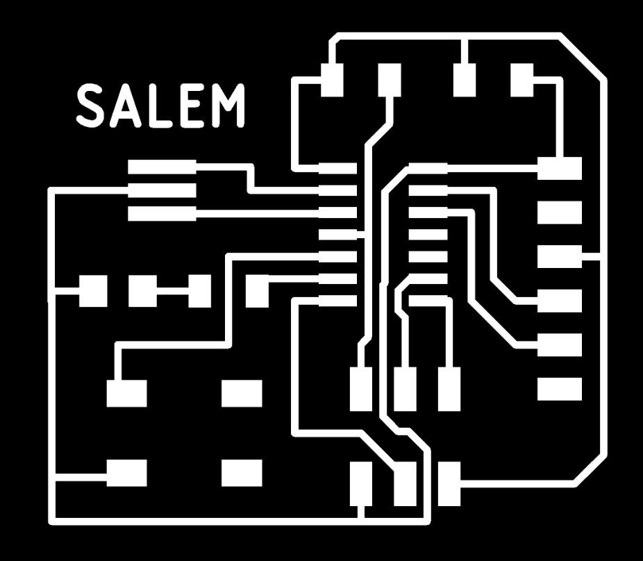
After routing all components there are certain requirements that are needed before exporting the image to GIMP or other relevant programs.
Turn off display pad names, signal names etc. Just to not confuse the milling machine with other informations on the board. For best results, routing routes should only be exported for the fabmodules and PCB making machine.
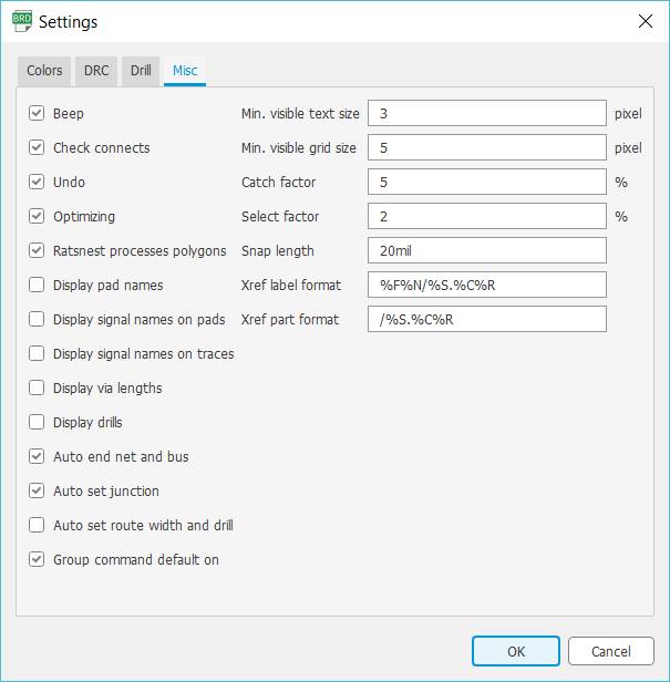
Only visible layer must be changed to only Top.
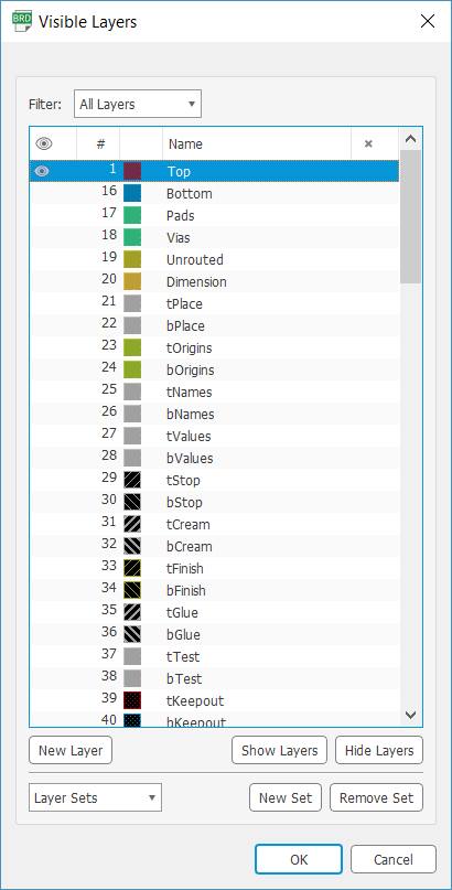
Results of the settings are as follows>
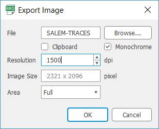
Export Image with resolution of 1500 dip
GIMP
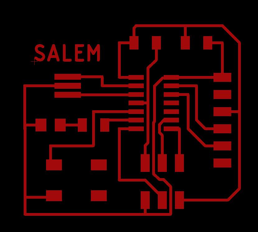
GIMP will be the tool used to make two different files from the exported image. Traces files and cutout files. (similar to previous guide)
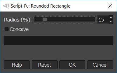
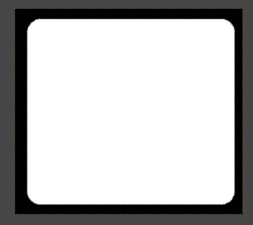
Cut out square line surrounding the tracing drawing.
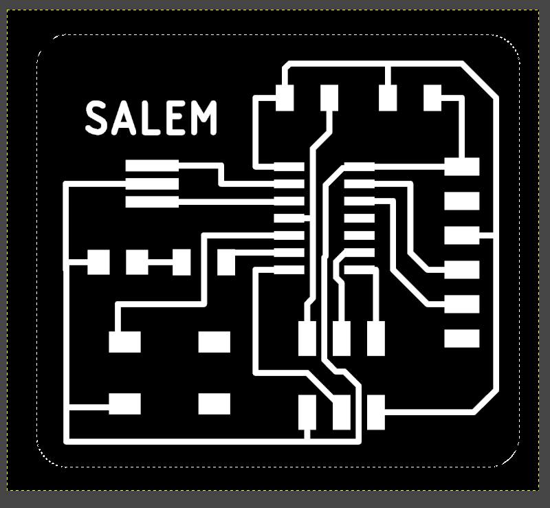
Results of cutout file.
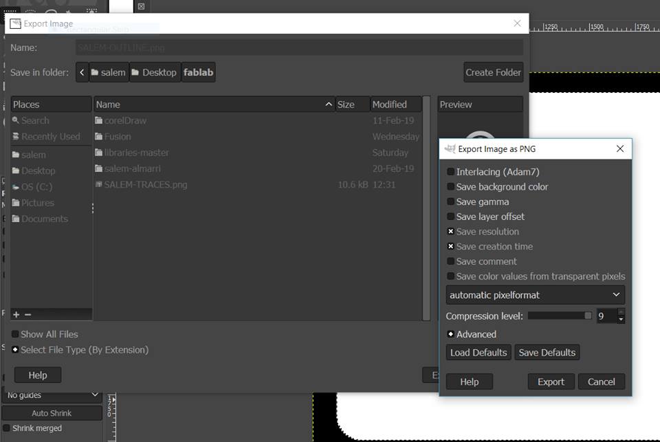
Export image as PNG for both files.
FABLab Modules
Exported files from GIMP are then uploaded to FABLab modules website. The user must confirm PNG dimensions with the intended design of the board.
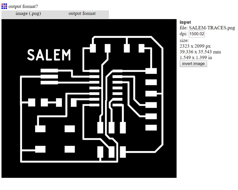
Routing for traces file

Routing for cutout file

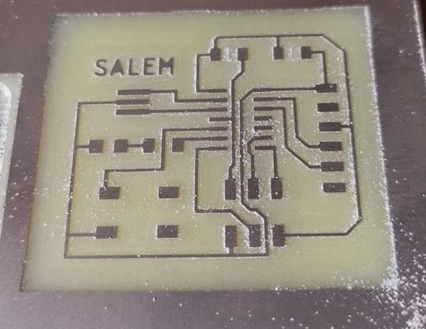
Circuit Board Fabrication
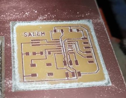
Results of traces file
Results of cutout file
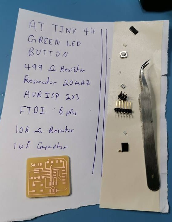
Preparation before soldering, the board must be cleaned with water and dried gently to remove copper residues. Before soldering, it is highly recommended to make a list of components that would be soldered on the designed board. Components must match FAB Academy's inventory. In addition I confirmed the components and their wiring schematic by searching the parts on Digikey website. Search results are as follows, ATtiny44, and button. Data-sheets referred to are ATTiny44 and button switch.
Soldering process.
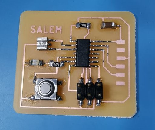
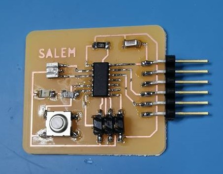
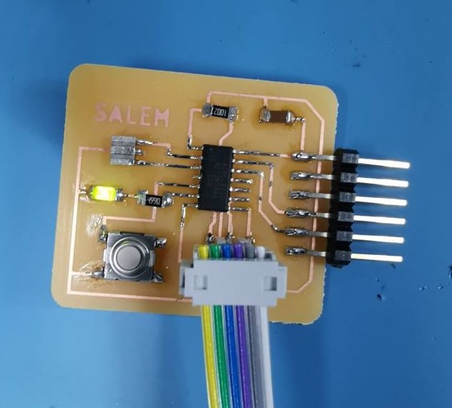
Results of soldering process.
Arduino IDE
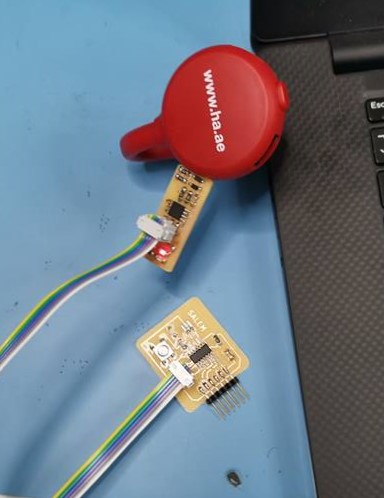
Connecting the USBTiny board made from week 5 with the newly fabricated echo hello-world board. Before doing this, it is recommended to check all connections using a multi-meter. Most importantly to find any shorts between VCC and GND. This is the only short that would cause severe damage PCB board.
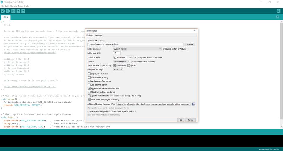
Following this guide to add ATtiny support to Arduino's IDE.
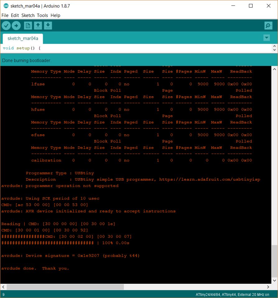
Proof of burning ATtiny44 using USBTiny45.
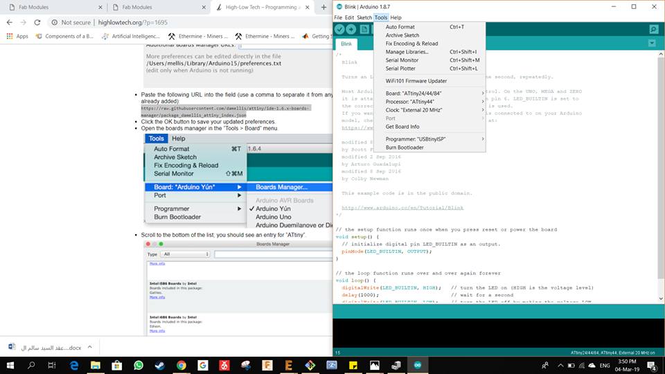
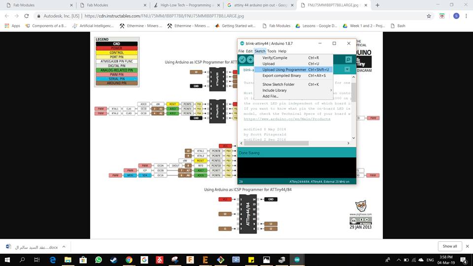
Programming ATtiny44 using Arduino's IDE. From this guide we can obtain the name of pins with respect to ATTiny44 to be programmed through Arduino's IDE. Also, to program we must dop through upload using programm Ctrl+Shift+U, and before that we must check again the board type, processor, and clock. (20 Mhz in our case)
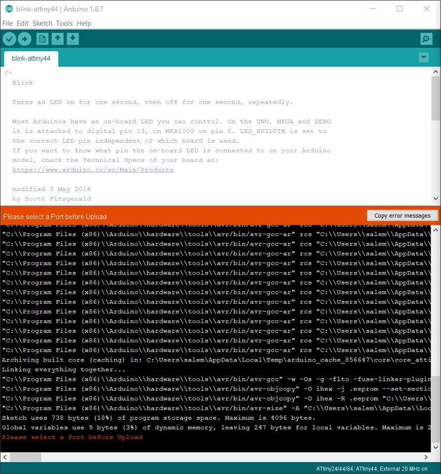
Error were returned by Arduino IDE asking to select port before upload, but we are not using a port in our case, we are using USBTiny. This error was then fixed by downgrading Arduino IDE to 1.8.5.
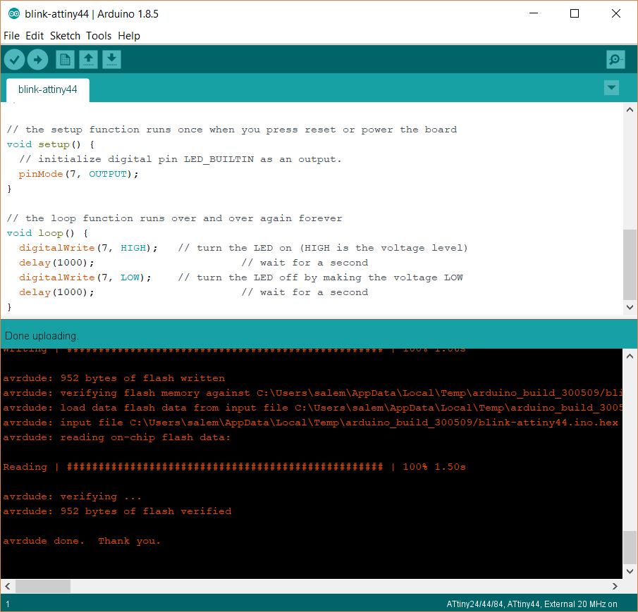
Successfully uploading the Blink program to the fabricated PCB.
Result proof were green LED is blinking.
Result proof in GIF format, it can be seen that the LED is always ON in green, and once the input button is pressed, the output of the LED becomes OFF.
Assignment Files:
echo hello-world board traces file
echo hello-world board outline file
Blink - ATTiny44
// the setup function runs once when you press reset or power the board
    void setup() {
// initialize digital pin LED_BUILTIN as an output.
    pinMode(7, OUTPUT);
}

// the loop function runs over and over again forever
void loop() {
  digitalWrite(7, HIGH);   // turn the LED on (HIGH is the voltage level)
  delay(1000);             // wait for a second
  digitalWrite(7, LOW);    // turn the LED off by making the voltage LOW
  delay(1000);             // wait for a second
}