17. Machine design
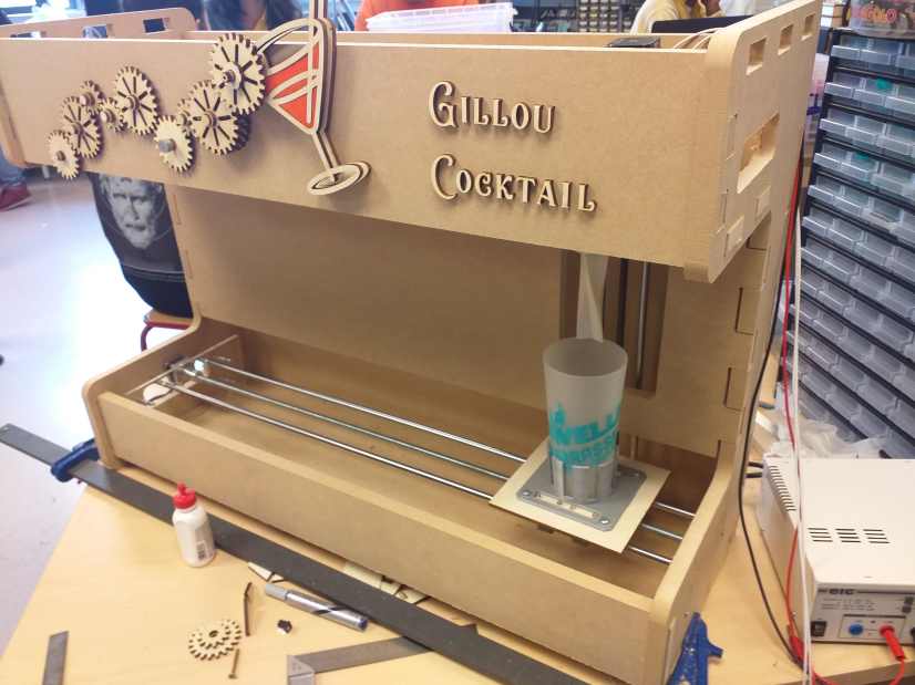
This week, in group, we continue the cocktail robot. On week 15 we start the project and built all the mechanical part. This week we had to work on the electronic and the automation/intelligence of the device.
Other components
For the other component, you are welcome to take a look at my fellow team students :
-
Stéphane Muller https://fabacademy.org/2019/labs/sorbonne/students/stephane-muller/
-
Madjid AIT SI AMER https://fabacademy.org/2019/labs/sorbonne/students/ait-siamermadjid/assignments/
-
Leo Lhermitte https://fabacademy.org/2019/labs/sorbonne/students/leo-lhermitte/
-
Julie Garnier https://fabacademy.org/2019/labs/sorbonne/students/julie-garnier/
Z axis and mixer
I had to control a DC motor, a stepper motor and I will use a contact switch to have a precise starting position.
In my case I would like to have several parameters : the height of the glasses, the speed of the mixer (and later eventually the duration of the mixing process).
Stepper motor
The stepper motor is controlled by a specialised component that need only 2 pins : a direction and a step.
I choose the The Pololu A4988 Stepper Motor Driver Carrier. Described here : https://www.pololu.com/product/1182 . The footprints and schematic for KiCad are linked : https://github.com/jharvey/Cinch_enclosure_template/tree/master/KICAD_Project/PCB-modules/pololu
With some code you have to send a High on the direction pin and the motor will have a rotation direction by sending a LOW, it will be the opposite direction.
To rotate the motor, you have to send a HIGH then a LOW on the step pin to move the motor of 1 step.
With my motor I need 200 steps to make a full turn. So I will need to send 200 times a HIGH and a LOW signal.
If you want to control the speed, you have to send more quickly or more slowly those HIGH and LOW signals.
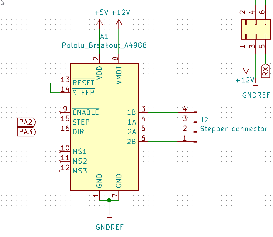
As described by the constructor the reset and sleep pin should be connected together. This component needs also a 5V for the logic parts. And of course the main power to power the stepper, in this case 12V. It outputs on 4 pins to control and power the motor.
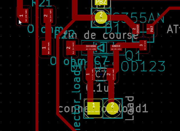
Mosfet to control the DC motor
To control the mixer, I will do the same as in the output week .
I use a mosfet transistor NDS355AN , I detail more on how to use it on week 12 .
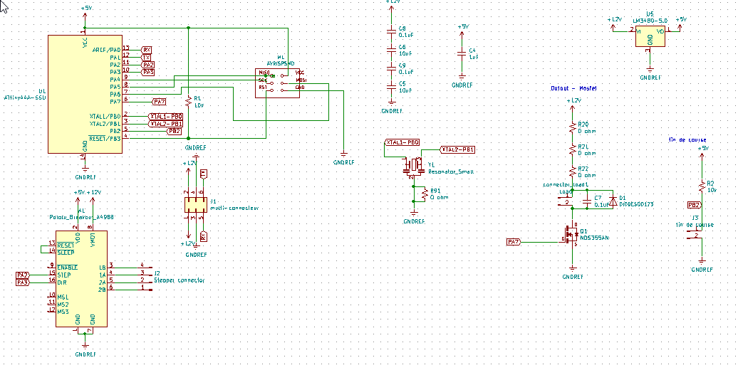
My design :
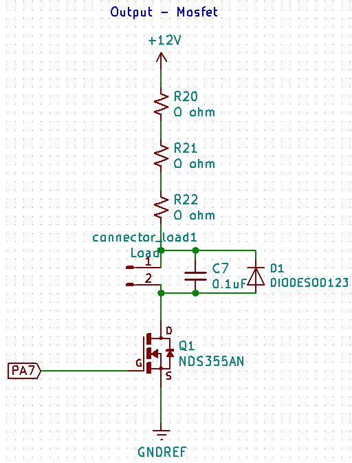
As you can see, I put a diode and a capacitor for the reverse current when the motor stops.
When I solder all the components it works but I had several reboot of the microcontroler. I miss a 10k resistor between the gate and the microcontroler !
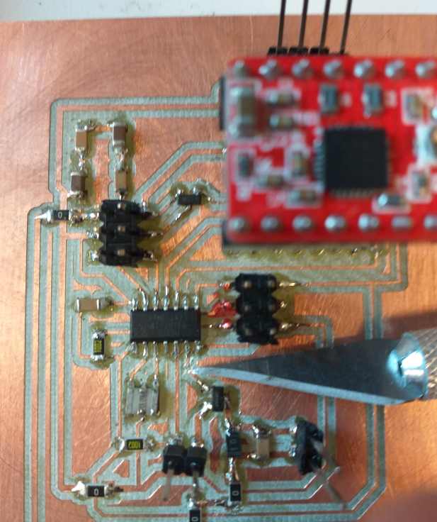
With a knife I cut the track.
And then I solder a 10K resistor.
Then everything works correctly.
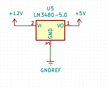
Power conversion
We decided to have a common 12V power. I will need the 12V to power the stepper but also the DC motor. But the microcontroller AtTiny 84 must be powered by a 5V.
I use a voltage regulator the LM3480 : Specification : http://www.ti.com/lit/ds/symlink/lm3480.pdf A regulator that will convert in our case the 12V to a 5V (max 100mA) to power the microcontroler.
100 mA is more than enought to power : the AtTiny, the low power part of the Stepper Motor Driver Carrier and some low power components.
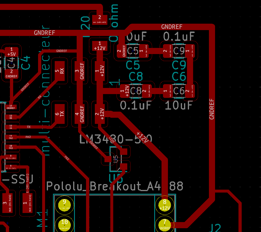
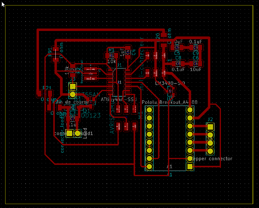
For the 12V elements I need to design wide tracks. I design them with 0.8mm. The stepper motor can consume up to 1 Amp.
For the wider track, it is important also for the ground. I design first with normal size the ground’s track, then I redraw them thicker. And in my case I need power for the stepper but also for the DC motor.
Switch for position
Then a simple design to connect a switch
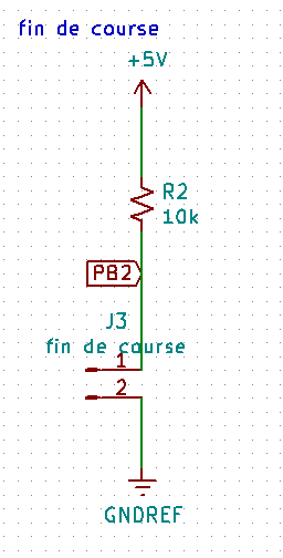
The switch is installed at a precise position.
During the initialisation, the motor will rotate till it touch the switch. It will reset a memory to zero and count each steps from that position.
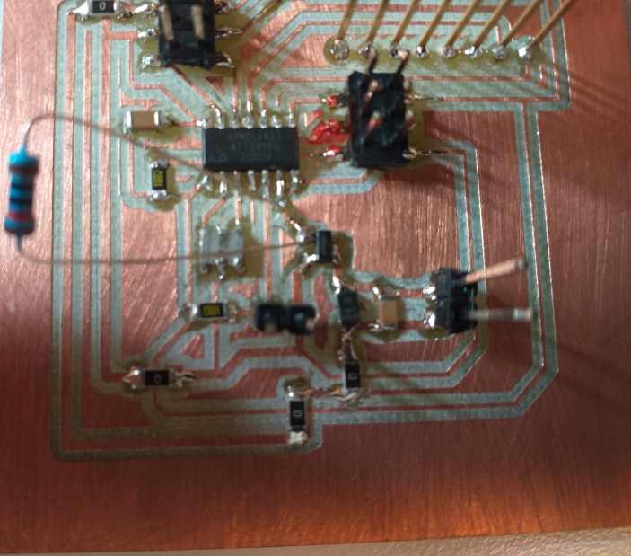
The full electronic design
Then soldered.
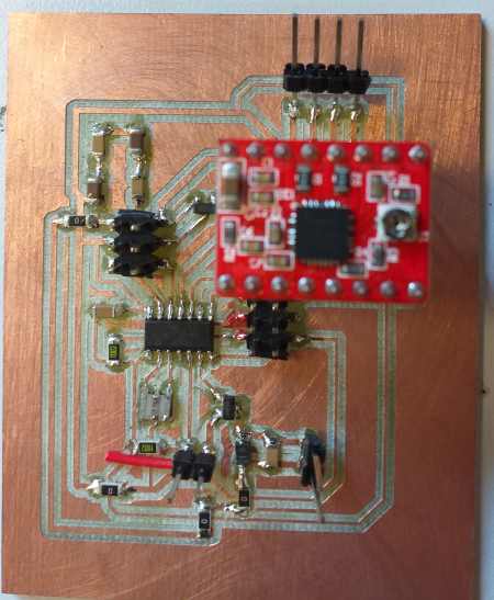
As it is difficult to see on only one picture, following other point of views.
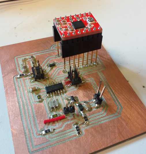
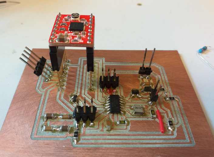
I had to improvise. I did not find all the connectors I want…
And as explained for the mosfet I had to add a resistor.
My designs files :
-
My KiCad files : mixeur_kicad.zip
-
My SVG to mill the traces : mixeur-F.Cu.svg
-
My SVG to cut the edges : mixeur-Edge.Cuts.svg
Test and debug code
I write some separate code to test and debug each parts : stepper_only_debug2.ino
#include <SoftwareSerial.h>

#define step_command 2 // PA2 _ 2 in Arduino
#define dir 3 // PA3 _ 3 in Arduino
#define mixer 7 // PA7 _ 7 in Arduino
#define fin_de_course 8 // PB2 _ 2 ou 8

//TX , PA1 , could be A0, 0 , 10
//RX , PA0 , could be A1 , 1 , 9

SoftwareSerial mySerial(A1, 0); // RX, TX

// address from 40 to 49
const byte code_start = 98;// code début : 98
const byte code_stop = 99;// code fin : 99
const byte adresse_chariot = 41;
const byte adresse_mixer = 42;

char received = 0;
int received_conversion;
byte decoded[3] = {0,0,0};

boolean fin_de_course_value;
int step_max = 1000;
int step_delay = 1000;

void setup() {
  pinMode(step_command, OUTPUT);
  pinMode(dir, OUTPUT);
  pinMode(mixer, OUTPUT);
  pinMode(fin_de_course, INPUT);

  mySerial.begin(9600);

  fin_de_course_value = digitalRead(fin_de_course);

  mySerial.println("HELLO");

}

void loop() {

  if(received == 49){
      digitalWrite(dir, HIGH);
              for(int i = 0; i <1000 ;i++ ){
            digitalWrite(step_command, HIGH);
            delayMicroseconds(step_delay);
            digitalWrite(step_command, LOW);
          }
  }

  if(received == 50){
            digitalWrite(dir, LOW);
              for(int i = 0; i <1000 ;i++ ){
            digitalWrite(step_command, HIGH);
            delayMicroseconds(step_delay);
            digitalWrite(step_command, LOW);
          }
  }


    if(received == 51){
        analogWrite(mixer, 100); // minimum 20 with this motor
  }

    if(received == 52){
        analogWrite(mixer, 0); // minimum 20 with this motor
  }

  fin_de_course_value = digitalRead(fin_de_course);

  if(fin_de_course_value == 0){
    //mySerial.print("recu :");

  }

  if(fin_de_course_value == 1){
    mySerial.print("boutton");

  }

}
When I send a 1 in ASCII , it rotates the stepper .
When I send a 2 in ASCII , it rotates the stepper in the opposite direction .
When I send a 3 in ASCII , it rotates the mixer at a 100 speed .
When I send a 4 in ASCII , the mixer stops .
When I press the switch, it sends by serial “button”.
This way I can check my electronics connection, power and all.
For those I used the serial command integrate in the Arduino software. It sends everything in ASCII and a carriage return.
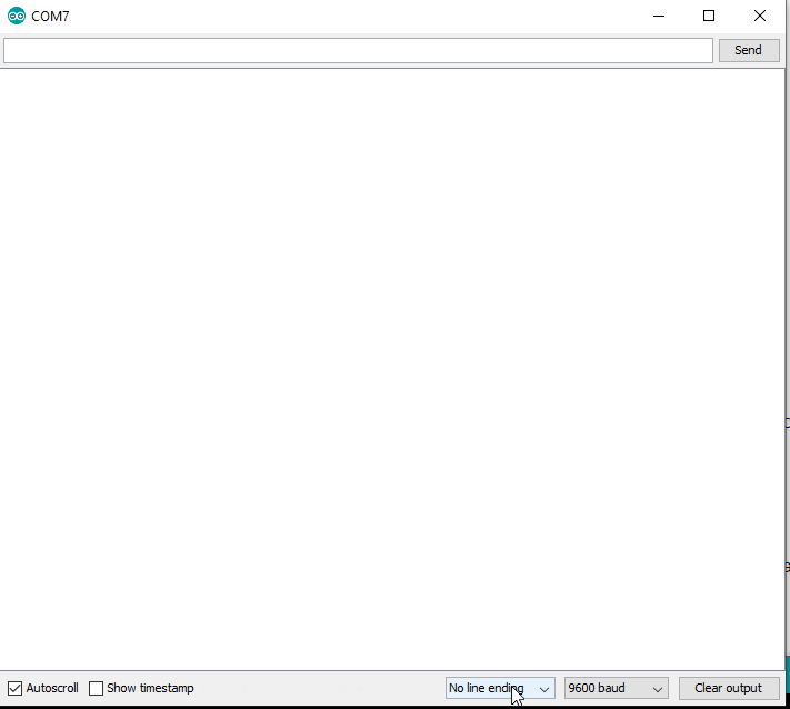
Be aware that If you click on line ending it will send another byte at each message sent.
RealTerm
It is impossible to see exactly what happens in serial with the terminal or Arduino.
To be sure I use another software, sadly only for windows called RealTerm https://realterm.sourceforge.io/, with that software you can display what you received in many formats.
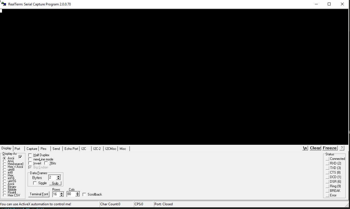
On the bottom of this window, you can check if the messages are displayed in ASCII. In my case I want to display them in uint8 , that means unsigned integer on 8 bit, So I will get a number between 0 and 255.
To select the correct port, bitrate, parity bit, bit lenght, stop bits and … This is located in the port tab.
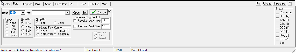
Finally to send some byte , you have to click on the send tab .
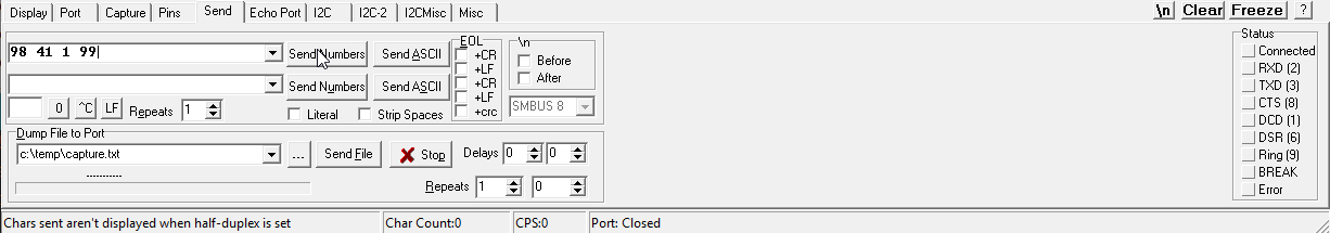
I fill the case with 98 41 1 99 and click on send Numbers .
With this software you can send message and write them in differents format like number , ascii characters, or hexadecimal values like 0xA2 .
It is really handy for understanding what is really sent and received !!!
Code
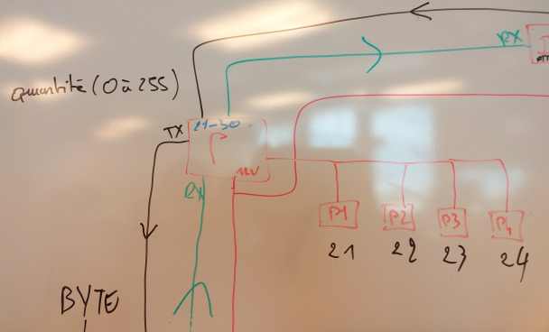
We decided together to have adress , start byte and stop byte.
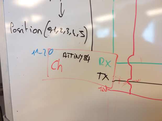
Each board has up to 10 adresses. My board is from 40 to 49. The Z motion is 41 and the mixer is 42.
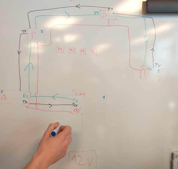
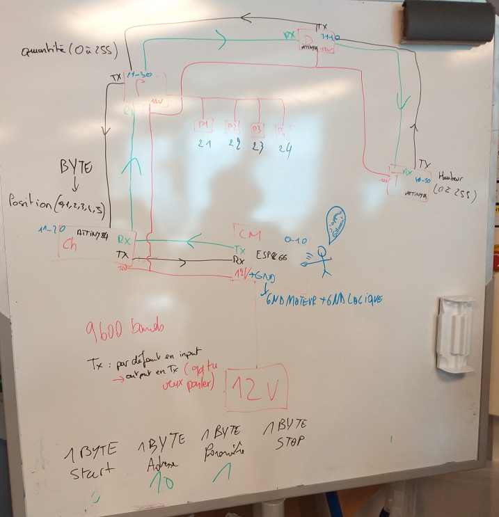
The ESP8266 from Leo Lhermitte is the master and send messages on his TX connected to our RX , and we respond from our TX to the master RX
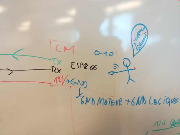
We share the same connector that bring the serial BUS and 2 pins for +12V and 2 pins for the ground.
As we need power up to 1 Amp, I hope 2 small wire of 24 AWG is enought.

As we have problem connecting all the board together, I am sure now that it is not enought to power several boards.
Start byte, stop byte, adresse
In the following code I defined some commands like
const byte code_start = 98;// code début : 98
const byte code_stop = 99;// code fin : 99
const byte code_confirm_receipt = 100; //100 accuse reception
const byte code_action_finished = 101; //101 fin d'operation
const byte code_ready_for_action = 102; //102 préparé
const byte adresse_chariot = 41;
const byte adresse_mixer = 42;
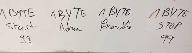
And each message should respect a 4 byte structure :
98 adresse message 99
So it will looks like
1100010 101001 00000001 1100011
98 = 1100010 is the starting byte and 99 = 1100011 is the stopping byte.
In my case I would like to have several parameters : the height of the glasses, the speed of the mixer (and later eventually the duration of the mixing process).
For the height of the glasses, I defined 3 height that are a message received on the addresse adresse_chariot = 41 , the message is 1 for a big glass, 2 for a medium glass, 3 for a small glass.
For the mixer, I allow a speed from 20 to 255 on a message received on the addresse adresse_mixer = 42.
So the master must send 98 41 1 99 to move the Z axis to the position of a big glass. Then it must send 98 42 20 99 for a “slow” mixing.
Serial communication on BUS
As the AtTiny has no buffer for a serial communication it is tricky. I build a function that received the bytes.
void lecture_reseau(){
    if (mySerial.available()) {
              received = mySerial.read();
                          if(received == code_start){
                            //mySerial.println("code start");mySerial.print(received);
                            while (mySerial.available() == 0) {
                            delayMicroseconds(1);
                            }
                            if (mySerial.available()) {
                            decoded[0] = mySerial.read();
                            }
                            while (mySerial.available() == 0) {
                            delayMicroseconds(1);
                            }
                            if (mySerial.available()) {
                            decoded[1] = mySerial.read();
                            }
                            while (mySerial.available() == 0) {
                            delayMicroseconds(1);
                            }
                            if (mySerial.available()) {
                            decoded[2] = mySerial.read();

                                    if(decoded[2] != code_stop ){
                                      decoded[0] = 0;
                                      decoded[1] = 0;
                                      //mySerial.print("pas bien");

                                    }

                            }
                          }
  }
The first byte is stored in received and must be equal to the code_start , then It waits for each byte and store them in an array called decoded[0] , decoded[1] , decoded[2] .
If decoded[2] is not equal to the code_stop then it is an error , and it reset the valor of the other decoded[0] , decoded[1].
Stepper and position
I create a function started at the beginning and after each cocktail. It moves the stepper till it touch the contact switch. Then it resets the memory position to 0
void chariot_initialisation(){
    fin_de_course_value = digitalRead(fin_de_course);
    digitalWrite(dir, HIGH);
    while(fin_de_course_value == 0){
        digitalWrite(step_command, HIGH);
        delayMicroseconds(step_delay);
        digitalWrite(step_command, LOW);
        fin_de_course_value = digitalRead(fin_de_course);
    }

    chariot_position = 0;
    //mySerial.print("fin de course");
    mySerial.write(code_start);mySerial.write(adresse_chariot);mySerial.write(code_ready_for_action);mySerial.write(code_stop);
}
The following function moves then the Z axis to another position stored in an array long chariot_hauteur[4] = {1000,15000,20000,24000}; , and actualise a memory with the last position.
void chariot_mouvement(long position_arrivee){

  nombre_de_pas = position_arrivee - chariot_position;

  //mySerial.print("nombre de pas a faire");mySerial.println(nombre_de_pas);

    digitalWrite(dir, LOW);
    for(int i = 0; i <nombre_de_pas ;i++ ){
        digitalWrite(step_command, HIGH);
        delayMicroseconds(step_delay);
        digitalWrite(step_command, LOW);
    }

    long chariot_position = position_arrivee;
    //mySerial.print("arrivee ");
    // envoi confirmation en position
    mySerial.write(code_start);mySerial.write(adresse_chariot);mySerial.write(code_ready_for_action);mySerial.write(code_stop);
}
I had measure several position stored like long chariot_hauteur[4] = {1000,15000,20000,24000}; depending on the height of differents glasses.
The full code
The code : mixer_002.ino
// to test z axis to position 1 ,  send 98 41 1 99
// to test z axis to position 2 ,  send 98 41 2 99
// to test mixer at a speed of 20 , send 98 42 20 99
// to test mixer at a speed of 100 , send 98 42 100 99

#include <SoftwareSerial.h>

#define step_command 2 // PA2 _ 2 in Arduino
#define dir 3 // PA3 _ 3 in Arduino
#define mixer 7 // PA7 _ 7 in Arduino
#define fin_de_course 8 // PB2 _ 2 ou 8

//TX , PA1 , Arduino 0
//RX , PA0 , Arduino A1

SoftwareSerial mySerial(A1, 0); // RX, TX

// address from 40 to 49
const byte code_start = 98;// code début : 98
const byte code_stop = 99;// code fin : 99
const byte code_confirm_receipt = 100; //100 accuse reception
const byte code_action_finished = 101; //101 fin d'operation
const byte code_ready_for_action = 102; //102 préparé
const byte adresse_chariot = 41;
const byte adresse_mixer = 42;

char received = 0;
byte decoded[3] = {1,2,3};

bool chariot_running = 0;
bool mixer_running = 0;

boolean fin_de_course_value;
int step_max = 1000;
int step_delay = 1000;

long chariot_position = 0;
long chariot_hauteur[4] = {1000,15000,20000,24000};
long chariot_arrivee = 0;
long nombre_de_pas;

int mixing_time = 10; // 10 seconds

void setup() {
  pinMode(step_command, OUTPUT);
  pinMode(dir, OUTPUT);
  pinMode(mixer, OUTPUT);
  pinMode(fin_de_course, INPUT);

  mySerial.begin(9600);

  fin_de_course_value = digitalRead(fin_de_course);

          // if the z axis is already touching, it is good to move it and make the initialisation
          if(fin_de_course_value == 1){
              digitalWrite(dir, LOW);
              for(int i = 0; i <4000 ;i++ ){
                digitalWrite(step_command, HIGH);
                delayMicroseconds(step_delay);
                digitalWrite(step_command, LOW);
              }
          }


  chariot_initialisation();

}

void loop() {

  lecture_reseau();

  if(decoded[0] == adresse_chariot && decoded[1] != 0){
        mySerial.write(code_start);mySerial.write(adresse_chariot);mySerial.write(code_confirm_receipt);mySerial.write(code_stop);
        chariot_mouvement(chariot_hauteur[decoded[1]]);
        mySerial.write(code_start);mySerial.write(adresse_chariot);mySerial.write(code_action_finished);mySerial.write(code_stop);

        reset_buffer();
  }

  if(decoded[0] == adresse_mixer && decoded[1] != 0){
            //mySerial.print("mixer");mySerial.println(decoded[1]);
            mySerial.write(code_start);mySerial.write(adresse_mixer);mySerial.write(code_confirm_receipt);mySerial.write(code_stop);
            analogWrite(mixer, decoded[1]);
            delay(mixing_time * 1000); // temps de mixage
            analogWrite(mixer, 0);
            mySerial.write(code_start);mySerial.write(adresse_mixer);mySerial.write(code_action_finished);mySerial.write(code_stop);

            reset_buffer();
            chariot_initialisation(); // start again
  }

}

void lecture_reseau(){
    if (mySerial.available()) {
              received = mySerial.read();
                          if(received == code_start){
                            //mySerial.println("code start");mySerial.print(received);
                            while (mySerial.available() == 0) {
                            delayMicroseconds(1);
                            }
                            if (mySerial.available()) {
                            decoded[0] = mySerial.read();
                            }
                            while (mySerial.available() == 0) {
                            delayMicroseconds(1);
                            }
                            if (mySerial.available()) {
                            decoded[1] = mySerial.read();
                            }
                            while (mySerial.available() == 0) {
                            delayMicroseconds(1);
                            }
                            if (mySerial.available()) {
                            decoded[2] = mySerial.read();

                                    if(decoded[2] != code_stop ){
                                      decoded[0] = 0;
                                      decoded[1] = 0;
                                      //mySerial.print("pas bien");

                                    }

                            }
                          }
  }

}

void reset_buffer(){
  decoded[0] = 0;
  decoded[1] = 0;
  //mySerial.println("reset buffer");
}

void chariot_initialisation(){
    fin_de_course_value = digitalRead(fin_de_course);
    digitalWrite(dir, HIGH);
    while(fin_de_course_value == 0){
        digitalWrite(step_command, HIGH);
        delayMicroseconds(step_delay);
        digitalWrite(step_command, LOW);
        fin_de_course_value = digitalRead(fin_de_course);
    }

    chariot_position = 0;
    //mySerial.print("fin de course");
    mySerial.write(code_start);mySerial.write(adresse_chariot);mySerial.write(code_ready_for_action);mySerial.write(code_stop);

}

void chariot_mouvement(long position_arrivee){

  nombre_de_pas = position_arrivee - chariot_position;

  //mySerial.print("nombre de pas a faire");mySerial.println(nombre_de_pas);

    digitalWrite(dir, LOW);
    for(int i = 0; i <nombre_de_pas ;i++ ){
        digitalWrite(step_command, HIGH);
        delayMicroseconds(step_delay);
        digitalWrite(step_command, LOW);
    }

    long chariot_position = position_arrivee;
    //mySerial.print("arrivee ");
    // envoi confirmation en position
    mySerial.write(code_start);mySerial.write(adresse_chariot);mySerial.write(code_ready_for_action);mySerial.write(code_stop);

}
Group video
My part working
Video :
Conclusion
My part works when I’m powering it and sending serial commands.
It has works several times with the Leo’s Board has master.
But it did not work when we connect several boards.
The same with Stéphane Muller’s board : it has works with Leo’s board. But as soon as it is connected with other boards it does not works.
Below some ideas of what goes wrong.
Power is not trivial
To power several boards, small wire is not a good idea.
We should also have consider to have a dedicated power in backup. If one board is doing strange things it has consequences on other boards. Especially if some boards don’t have track wide enought.
As I am at the end of the chain I do not have 12V, with up to 2 meters of cable, I have already a drop of more than 0,6V so 11,4V.
If the first board draw current, I don’t have enough to power my motor and the microcontroler is not powered anymore and reboot as soon as a little bit of current is available.
Stepper motor draw current all the time and not only when they rotate. So our installation can draw up to 4 or 6 Amps , about 1 amp per stepper motor : 1 amp for the X axis, 1 amp for the Z axis, 0.3 amp for the mixer DC motor, and 1 amp per stepper for the peristatic pump for each alcoohol (the idea was to have 4 alcoohol).
Serial communication is not trivial.
I take a lot of time to manage a “simple” communication with 4 bytes , start byte, stop byte, adresse byte and message. With this sollution I avoid several situation that could happens.
Long wire is not a good idea.
To improve our system we should have implemented some checksum and/or error correction bytes.
To build a serial protocol from scratch and implement all the needed features is complicated. That is why, peopel rely on standard protocols with reliable library.
Files
The debug code, to test each components : stepper_only_debug2.ino
The final code : mixer_002.ino
My KiCad files : mixeur_kicad.zip
My SVG to mill the traces : mixeur-F.Cu.svg
My SVG to cut the edges : mixeur-Edge.Cuts.svg