5. Electronics production
This week assignement is to build an ISP programmer. We have to use a CNC to produce the board, then solder the components, compile and flash the code on the atTiny.
Another task is to test some patterns with the CNC and try differents milling bits.
I choose the FabTinyISP Brian’s version : http://fab.cba.mit.edu/classes/863.16/doc/projects/ftsmin/index.html
CNC milling for electronics
I use a Roland SRM-20 , it’s the common CNC for the FabAcademy. I use the Vpanel software : you have some arrows to position the milling and you can memorize the position as origin. Then you can send gcode or RML to the CNC. RML is a code created by Roland.

In the specification Roland claim that RML can send command to up 0.01mm but with gcode you can go up to 0.001mm SRM-20 specification
I’ve make the pattern test with first a 0.4 mm 2 flute , but it brake, the 4 mm / s was to quick . I had no other bit of that size.


Then I test V shape bit of 45° and 0.1 mm , their I can go at 4 mm / s but if your Z origin is precise you’ll get wider cut.

I switch later to V shape bit of 15° and 0.1 mm , their I can go at 4 mm / s


I can expect a really high definition. Most of the problem comes from the flat surface ! And to find the precise origine with Z.
I didn’t had time to test a system that can compensate this problem of “flatness”, it measure with an electric contact in several point on the board and compensate the gcode .
The pattern milled but unclean

I’ve tried to optimised the Z position, and played with another Vshape bit.

Remarks
I have to mill slowly because the board are made of FR4. FR1 is not available in many countries. Later in this FabAcademy I want to use solder paste and oven, in those cases FR1 is strictly FORBIDEN, it will burn in the oven .
FR4 is more strenuous and wear a lot the mill. As I milled with FR4 board my parameters are adapted and I tested them a lot by breaking several mills.
Creating the gcode
I used mods from Neil : http://mods.cba.mit.edu/
I select program then open server program then mill 2D png

But it did not produce a compatible gcode for the SRM20
The correct solution in my case was to use the program then open server program then Roland/mill/SRM-20/PCB

To produce the file I had to add another module called file save

Then I change the origin to x y z : 0 0 0 , I put the speed at 2 mm / s and increase progressively on the vpanel software . Then I click on calculate get a file and a visualisation of the tool path. Here with 4 path around the shape .

Then I produce another file to cut the edge. With a step of 0.5 mm for a final cut of 2.0 mm , so it’ll make 4 pass to cut-out. The visualisation difference is the blue arrow of orientation on the left is bigger …

The result :

Then with a knive, I remove the last part and check the visual aspect.

Soldering
First of all, I identify and double check every component that I place in small trays with clear annotation. I made a mistake in the orientation of a LED, annotation are really tricky and not universal !

My main problem was the size of the tip of my soldering iron : 2.4 mm is to big for SMT . I received too late a 1.0 mm tip and everything was really easyer after that.
So I began with the smaller and component at the center.

Then I’ve solder the resistors and the diode zener .

Then the LED and last resistors .

Then the connector and the usb connection .


Then I check the connections

Programmer and Led light
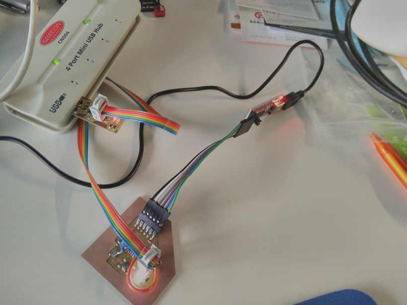
I connect the board to an usb power and the red light is correctly powered. First victory ! The MISO is also on the right pin and when powered through the other ISP programmer the red light is also bright .


install linux, install the software and build the code
I’ve follow the steps from http://fab.cba.mit.edu/classes/863.16/doc/projects/ftsmin/index.html
download the source file, go in the correct directory and compile it with :
make

Then I get a fts_firmware.hex file.
I’m using a usbtiny programmer made by Sparkfun, but I solder a aTtiny85 in place of the aTtiny45, so I modify the Makefile file and compile it again.
Problem : I’m using Ubuntu on windows 10 and clearly it is a bad idea. I never succeed to communicate with usb ports.

After some test on a board of my fellow fabacademy friends, I discover that one pin of the AtTiny was badly soldered. I also install a full linux (only command line) on an old computer at AgriLab, it has usb2 as standard usb port.
I resolder the pin. And it works : I flash correctly the program.
I can’t make screenshot on that linux computer as it has only a command line.
I updated the Makefile with the right AVR programmer and the correct AtTiny model an attiny85 .
# Set up which MCU you're using, and what programmer, and the clock speed
# here.
MCU = attiny85
PROGRAMMER ?= usbtiny
F_CPU = 16500000UL
My programmer is based on the usbtiny, it’s the Pocket AVR Programmer from Sparkfun (https://www.sparkfun.com/products/9825)[https://www.sparkfun.com/products/9825]
I use the following commands :
make fuses
Then
make flash
And finally
make rstdisbl
I remove then the solder bridge.
Later I used the programmer on a USB 1.1 connected to my latop to flash program like in week 09,
Error and failures
Milling, I broke several milling bits :
- I didn’t hold correctly the collet and it falls severals centimeter and break the milling bit .
- I use the default speed wich was too high: It breaks a milling bit. Now , I put a lower speed and increase slowly the percentage of the speed in Vpanel .
Soldering, I didn’t have all the tools ready … I got a 2.4 mm tip for soldering, and that’s too big for SMT. I order too late a 1 mm tip and that was easier. I use a big lens most of the time to see what I am doing.
Don’t bellieve in documentation and standard symbol. Nothing is standard. Just test and test again. The symbol on my red LED was inverted, I had to desolder the component, test it and invert the orientaiton and solder it again. On that subject I recommand everybody to read The Hardware Hacker written by Andrew “bunnie” Huang https://nostarch.com/hardwarehackerpaperback , especially the chapter “Counterfeit chips in US millitary Hardware” .
Linux on Windows 10 is a bad idea. Too much problems. Never suceed to communicate with usb port…
Photos : Don’t expect too much of the camera of your mobile phone. I’ve to find a good lens and a reflex to take some pictures. It’s too close to the object and it’s really small.
Tips and Tricks
I use some SmartTwezer , it gives the value of the components precisely. You can avoid to make some mistake that way.

I plan to test another software : FlatCAM http://flatcam.org/ , it can produce gcode from gerber files or from a png and is opensource
Files
To flash the atTiny85 fts_firmware.hex and fts_firmware.elf
My RML files with 0.4 two flutes: correct04-001_origine0_slower.rml With the vcut : trace001v.rml and the external cutout cut.rml