12. Output devices
This week I work on output : motor, mosfet, power, H-bridge,…
For the group assignement I have to caracterise and measure a brushless motor contorled by an ESC.
Group , measure the current/tension
I measure the current and tension on an ESC , HobbyKing 30A ESC 3A UBEC , reference : https://hobbyking.com/en_us/hobby-king-30a-esc-3a-ubec.html powering a brushless motor NTM Prop Drive 28-26 1000KV / 235W , reference : https://hobbyking.com/en_us/ntm-prop-drive-28-26-1000kv-235w.html
The motor could be powered up to 235W, 15A and 1000kV and the ESC could handle 30A !
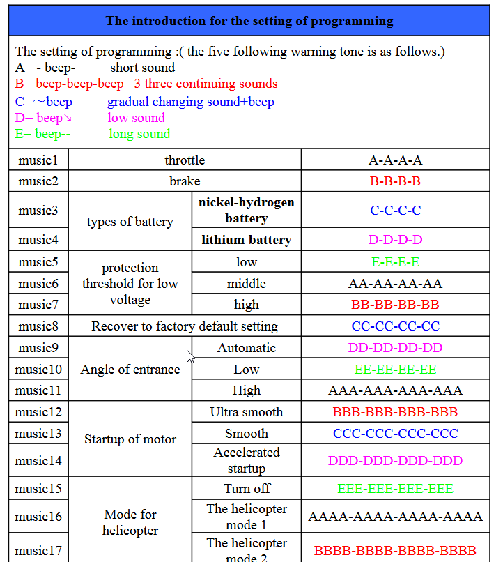
Their is a procedure of setup. I read the manual and specification. The controler is setup with some tone/music.
To start any sequence you have to send a low then a hight pulse. It confirms the setup. Then you can send the value you want to the motor. It’s a PWM at 50 Hz. The low value must be 1000 microseconds the high value 2000.
I just modify a simple code from https://www.firediy.fr/article/calibrer-ses-esc-avec-un-arduino-drone-ch-3. I change to pin 11 and delete some part of the code to control only one motor.
This code use the library servo.h , it use timers of the Attiny44 to have a precise PWM. The Servo library was purposed for servomotor, in this code it uses value from 0 to 180° that are corresponding to a PWM of 1000microseconds to 2000 microseconds with that declaration :
motA.attach(11, 1000, 2000);
A smarter way is to use directly writeMicroseconds() .
Here the code, ESC_values.ino
/**
 * Usage, according to documentation(https://www.firediy.fr/files/drone/HW-01-V4.pdf) :
 *     1. Plug your Arduino to your computer with USB cable, open terminal, then type 1 to send max throttle to every ESC to enter programming mode
 *     2. Power up your ESCs. You must hear "beep1 beep2 beep3" tones meaning the power supply is OK
 *     3. After 2sec, "beep beep" tone emits, meaning the throttle highest point has been correctly confirmed
 *     4. Type 0 to send 0 throttle
 *     5. Several "beep" tones emits, wich means the quantity of the lithium battery cells (3 beeps for a 3 cells LiPo)
 *     6. A long beep tone emits meaning the throttle lowest point has been correctly confirmed
 *     7. Type 2 to launch test function. This will send 0 to 180 throttle to ESCs to test them
 */

#include <Servo.h>

Servo motA;
char data;

/**
 * Initialisation routine
 */
void setup() {
    Serial.begin(9600);

    motA.attach(11, 1000, 2000); // 1000 and 2000 are very important ! Values can be different with other ESCs.

    displayInstructions();
}

/**
 * Main function
 */
void loop() {
    if (Serial.available()) {
        data = Serial.read();

        switch (data) {
            // 0
            case 48 : Serial.println("Sending 0 throttle");
                      motA.write(0);
            break;

            // 1
            case 49 : Serial.println("Sending 180 throttle");
                      motA.write(180);
            break;

            // 2
            case 50 : Serial.print("Running test in 3");
                      delay(1000);
                      Serial.print(" 2");
                      delay(1000);
                      Serial.println(" 1...");
                      delay(1000);
                      test();
            break;
        }
    }
}

/**
 * Test function sending angle to the ESCs from 0 to 180 degrees
 */
void test()
{
    for (int i=0; i<=180; i++) {
        Serial.print("Speed = ");
        Serial.println(i);

        motA.write(i);

        delay(200);
    }

    Serial.println("STOP");
    motA.write(0);
}

/**
 * Displays instructions to user
 */
void displayInstructions()
{
    Serial.println("READY - PLEASE SEND INSTRUCTIONS AS FOLLOWING :");
    Serial.println("\t0 : Sends 0 throttle");
    Serial.println("\t1 : Sends 180 throttle");
    Serial.println("\t2 : Runs test function\n");
}
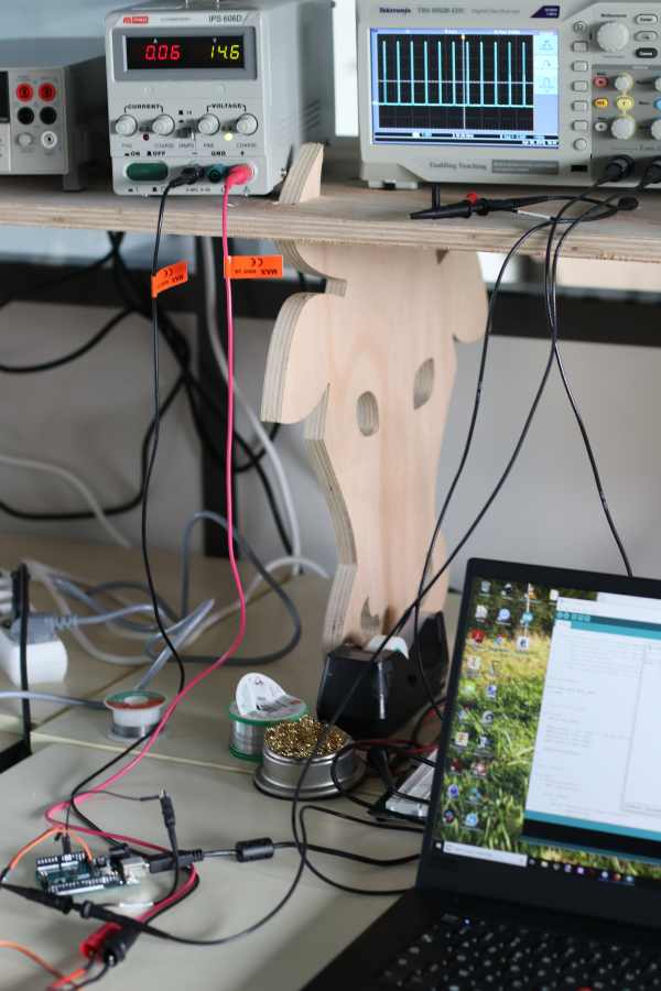
Test setup
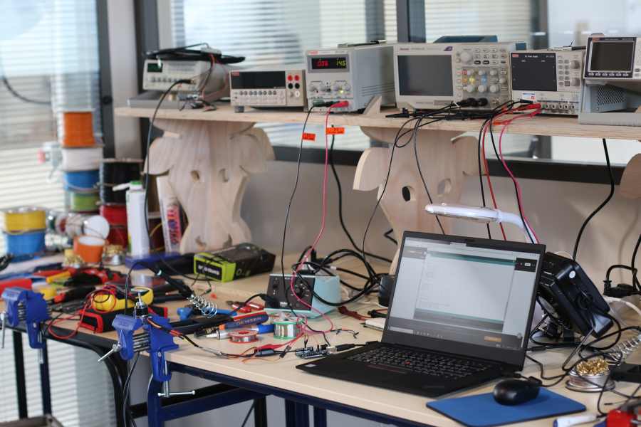
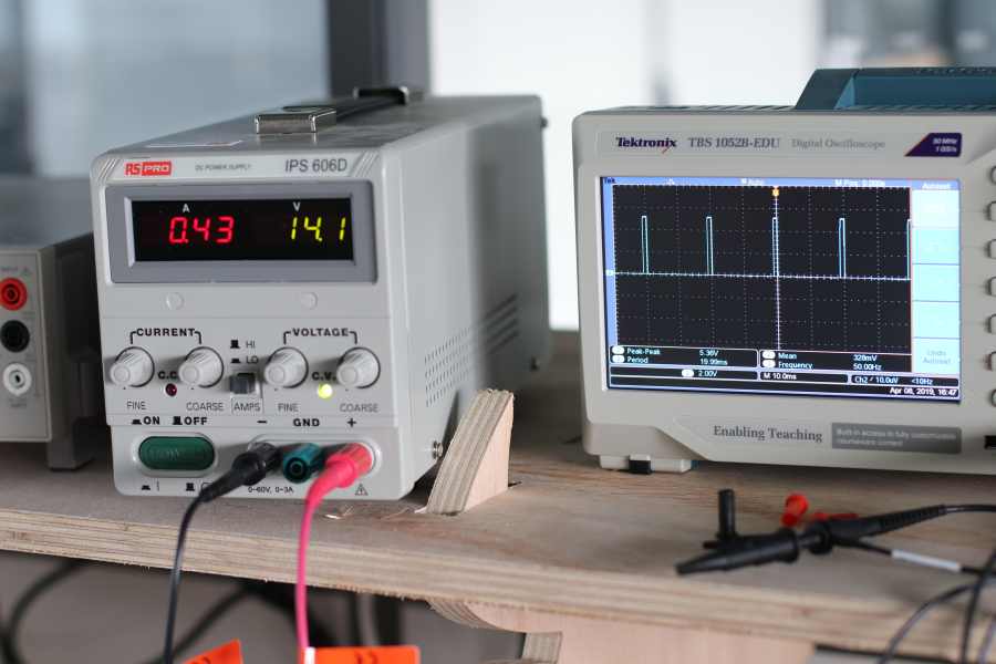
I have to use a computer, an Arduino, an electric power, and the oscilloscope to visualise what I’m doing, the ESC and the motor.
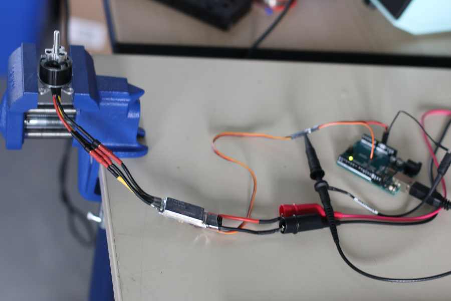
The arduino is connected to the pin 11 who gives the PWM and to the ground those two pins are connected to the low power part of the ESC.
The electric power is connected to the high power part of the ESC.
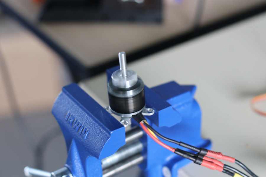
Then the ESC is connected with 3 wires to the motor. As the voltage and current can be extremely high, I prefer not to monitor those. The oscilloscope could handle 300V but the ESC mention several kV…
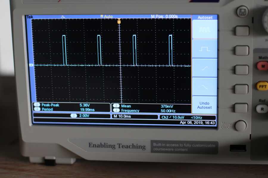
I monitor the PWM, the oscilloscope is connected to the pin 3 and the ground of the Arduino.
The electric power gives the current value.
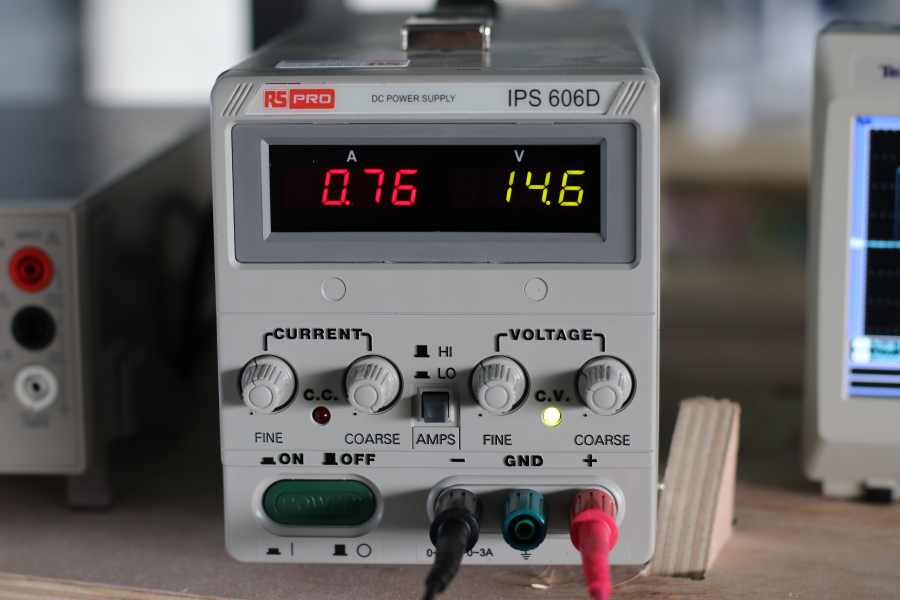
I have clamped the motor. It could be dangerous as it will rotate at really high speed.
Now I can monitor the tension and current send to the ESC and the PWM sent by the arduino
You have to open the terminal.
At the startup you type “0” and confirm , this send a low PWM value, a pulse width of 1000 microsecond.
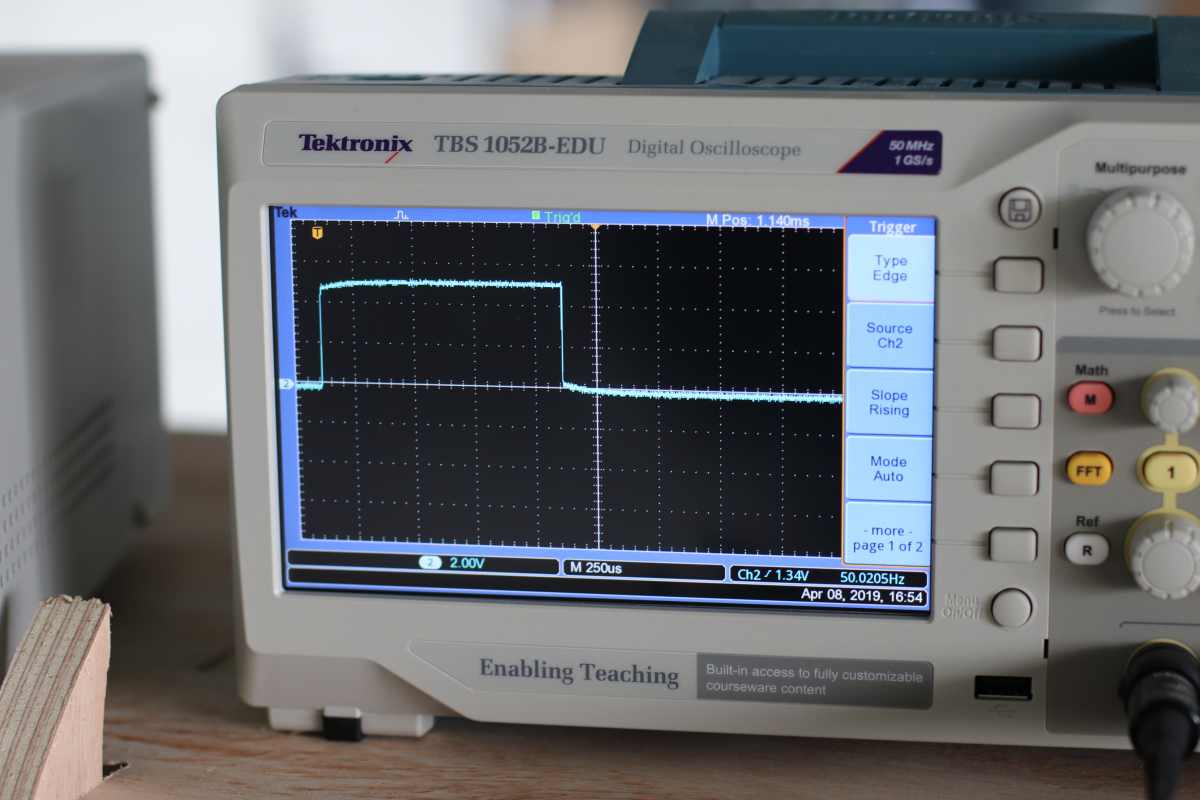
Then you type “1” and confirm , this send a high PWM value, a pulse width of 2000 microsecond.
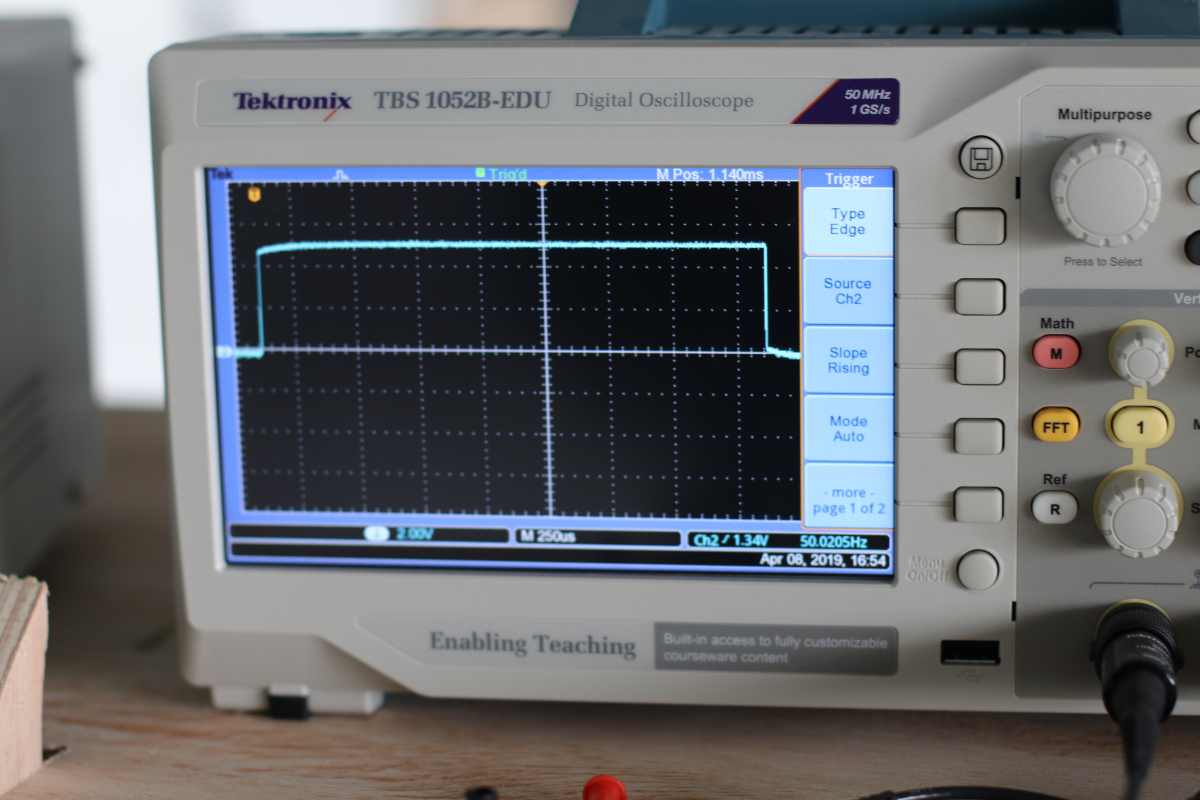
When you type “2” , it sends an increasing PWM value from 1000 to the maximum value 2000 microsecond.
To change the setup, you have to understand the music pattern made by the controler.
Output
I design an output with a mosfet and an input with a phototransistor (because I did not finish last week assignment). I want to be safe with the timing, so I use an Attiny44 as the previous week. I really like to test an ESP32 but it will take more time to design and understand.
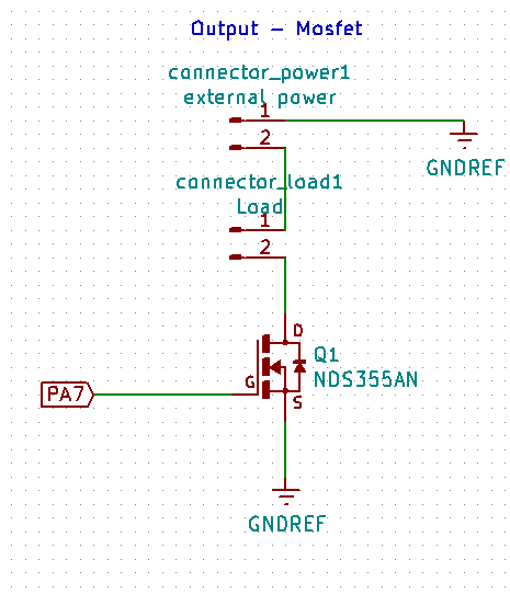
As it is a n-mosfet, the Load get the current goes to the drain is controlled by the gate and get out via the source to the ground.
Transistor NDS355AN , specification on https://www.digikey.com/product-detail/en/fairchild-semiconductor/NDS355AN/NDS355ANCT-ND and https://www.onsemi.com/pub/Collateral/NDS355AN-D.PDF
It can accept 30V and 1.7A , I will certainly keep it for my final project where I need to control 24V and 1 A.
Have to find the KiCad’s footprint on SnapEDA
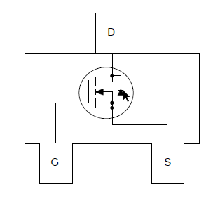
It’s an n-mosfet , so the load must be connected to the drain and to the VCC
I had several connectors for the Load, the external power and I want to have the 5v from another source that the FTDI or ISP.
Input
For the Phototransistor, I have a VEMT3700. I had many problem with the footprint and kicad. I had to select another component to have the correct footprint ! So it looks like a resistor but I will place the phototransistor in the correct orientation.
![]()
Trace
My trace.
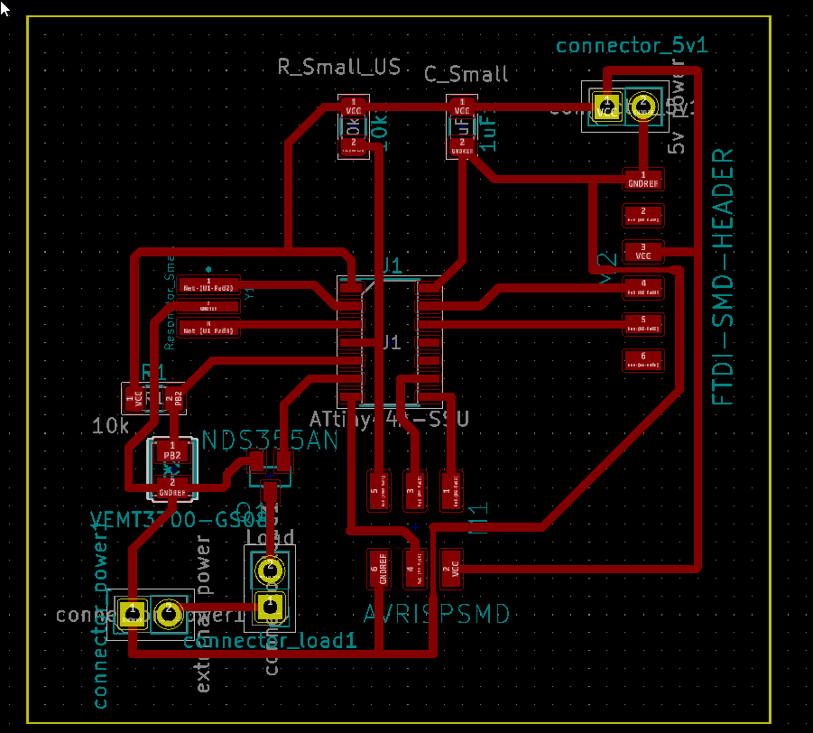
This time I design wider trace, 0.6 mm , I have 2 smaller traces (0.4 mm) that need to be close to pads.
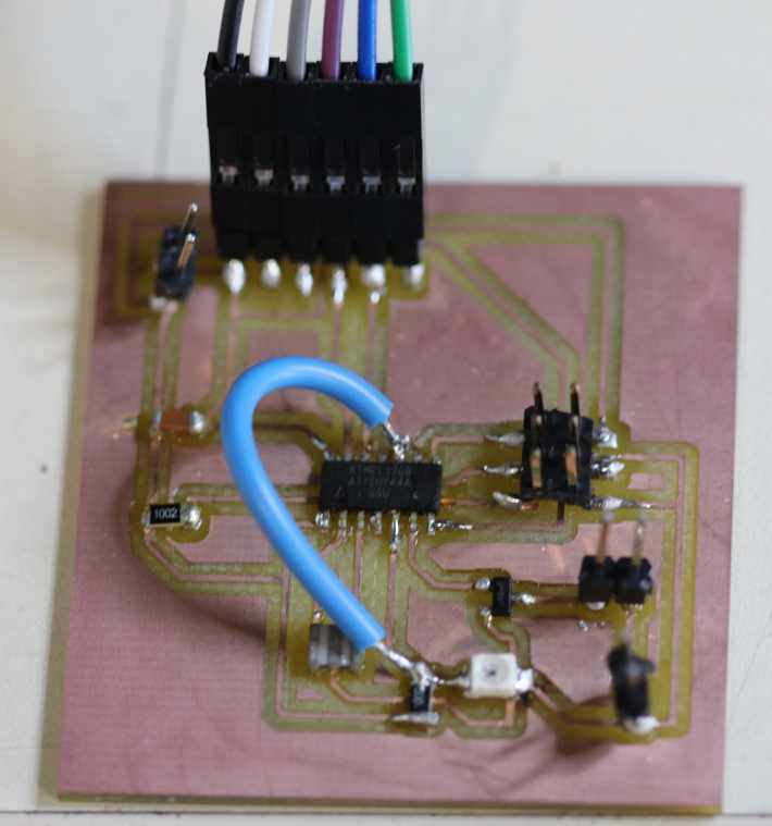
PCB Board
I do not detail the whole process for the milling of the board. Take a look at the previous weeks.
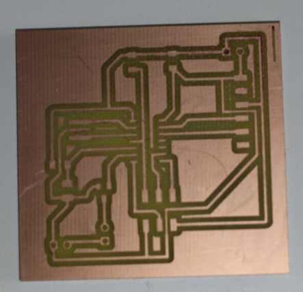
I use solder paste, pick and place and oven as describe on week 11
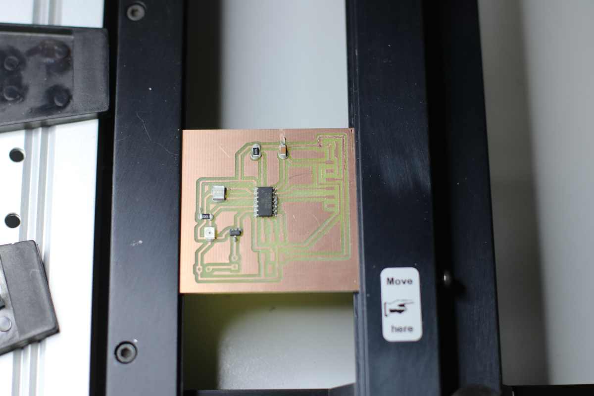
This time I have not made the mistake of putting the connector with plastic part. I know it will melt in the oven …
Then I solder the connectors and check all the connections.
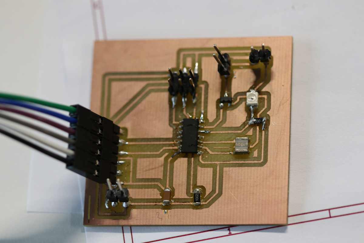
You could see on this picture that I had put more solder on some connections.
Then I connect the Load, here a fan. An external power of 12V to power the fan. And a 5V to power the board. I use a breadboard and some wire to connect everything.
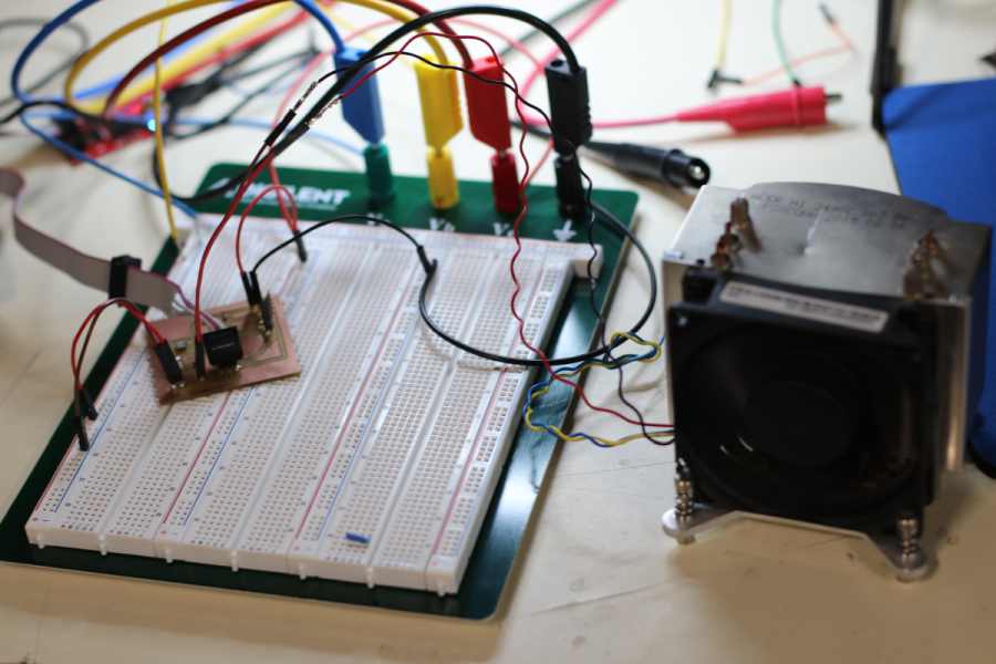
But a fan is a motor. It does not stop immediatly and will produce reverse current when spinning down. To power a motor and protect the circuit some Diode and condenser should be placed in the patch. Adel Kheniche, our local instructor advise me to power a bunch of LED instead.
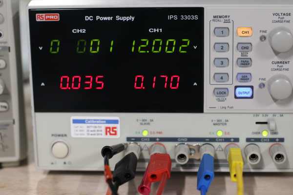
The power comes from a stabilised power, where I can check the consumption.
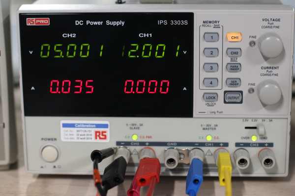
When the mosfet is on : 170mA @ 12V
When the mosfet is off : 0 mA @ 12V
This was commanded by the following code : output_on-off.ino
#include <SoftwareSerial.h>

//TX , PA0 , could be A0, 0 , 10
//RX , PA1 , could be A1 , 1 , 9


const int mosfet = 7; // connected to PA7 or 7 in arduino
const int phototransistor = 8; // connected to PB2 or 8 in arduino
const int timing = 6000;

SoftwareSerial mySerial(0, A1); // RX, TX

void setup() {

  pinMode(mosfet, OUTPUT);

}

void loop() {

  digitalWrite(mosfet, HIGH);
  delay(timing);
  digitalWrite(mosfet, LOW);
  delay(timing);

}
Then I control the mosfet with an increasing PWM value with the following code : output-PWM.ino
#include <SoftwareSerial.h>

//TX , PA0 , could be A0, 0 , 10
//RX , PA1 , could be A1 , 1 , 9


const int mosfet = 7; // connected to PA7 or 7 in arduino
const int phototransistor = 8; // connected to PB2 or 8 in arduino

int value = 0;
int timing = 50;

SoftwareSerial mySerial(0, A1); // RX, TX

void setup() {

  pinMode(mosfet, OUTPUT);

}

void loop() {

  for (value = 0; value <= 255; value += 1) {

    analogWrite(mosfet, value);
    delay(timing);
  }
  for (value = 180; value >= 0; value -= 1) {
    analogWrite(mosfet, value);
    delay(timing);
  }

}
Input
I made the mistake of connecting the phototransistor on PB2. This pin does not have an ADC.
I solder a wire connection to PA 3 and it works now , I can read the value.
The following gives changing values : read-photo.ino
#include <SoftwareSerial.h>

//TX , PA0 , could be A0, 0 , 10
//RX , PA1 , could be A1 , 1 , 9

const int mosfet = 7; // connected to PA7 or 7 in arduino
const int phototransistor = A3 ; // connected to PA3 , A3 in arduino

int photovalue = 0;
int timing = 50;

SoftwareSerial mySerial(0, A1); // RX, TX

void setup() {
  mySerial.begin(9600);
  pinMode(mosfet, OUTPUT);
  pinMode(phototransistor, INPUT);
}

void loop() {
    photovalue = analogRead(phototransistor);
    mySerial.println(photovalue);
    delay(timing);
}
When I put some bright light on the phototransistor , the value move from 1010 to 20.
Combining input and output
I combine the input and the ouput here : combined_input_output.ino
#include <SoftwareSerial.h>

//TX , PA0 , could be A0, 0 , 10
//RX , PA1 , could be A1 , 1 , 9

const int mosfet = 7; // connected to PA7 or 7 in arduino
const int phototransistor = A3 ; // connected to PA3 , A3 in arduino

int photovalue = 0;
int timing = 5;
int mapedvalue = 0;

SoftwareSerial mySerial(0, A1); // RX, TX

void setup() {
  mySerial.begin(9600);
  pinMode(mosfet, OUTPUT);
  pinMode(phototransistor, INPUT);
}

void loop() {
    photovalue = analogRead(phototransistor);
    mySerial.println(photovalue);
    delay(timing);

    mapedvalue = map(photovalue, 0, 1024, 0, 255) ;

    analogWrite(mosfet, mapedvalue);
}
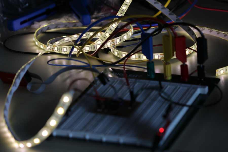
When I approach some external light the bunch of LED is less bright till dark. When the external light disapear, the bunch of LED is brighter.
The input has a 10bit resolustion giving value to 1024 but the PWM ouput connected to the mosfet is 8 bit, it accept value till 255. The map function does the conversion :
mapedvalue = map(photovalue, 0, 1024, 0, 255) ;
Of course you could write your own conversion with a few lines of code.
Conclusion
I design a board with a mosfet control it with some code, then control it with an imput. The mosfet will be usefull for my final project.
I take the time to look around on the connector subject. I learn more on medium volume and industrial process of programming component of board. Some keywords : tag-connect , pogo pin , programming fixture. Interesting links : https://macrofab.com/blog/designing-pogo-pin-programming-cables-intro-tag-connect/ , https://macrofab.com/blog/design-build-simple-programming-fixture/ and https://www.sparkfun.com/tutorials/138 .
Final Project
Here I installed the piezzo electric element of the fog maker controlled by the mosfet.
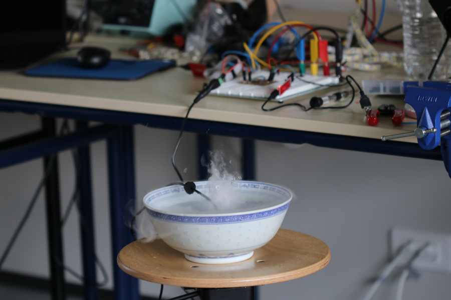
It is powered by 24V and consume less than 700mA.

Files
Arduino ESC code : ESC_values.ino
MOSFET fully on then off : output_on-off.ino
Increasing PWM on the mosfet : output-PWM.ino
Reading of the input of a photo-transistor : read-photo.ino
Combined input and output : combined_input_output.ino
KiCad design and traces : kicad_output.rar or kicad_output.zip