3. Computer design
The goal of this week is to test diffrents CAD software and start modelisation of final project.
To do this week
- Try to use and compare: Solidworks, Fusion360 and FreeCad
- Try to use and compare 3D cad software: Solidworks, Fusion360 and FreeCad
- Try to use and compare scripting cad tools: OpenJSCad, python, ...
CAD softwares homeworks
For me, this week is a great challenge. I already try to use some cad software before like Blender, Thinkercad and a little bit fusion 360. But I was not used to create new design. I was just able to make some updates on models that I have find in thingiverse.
FreeCad
Let's try
In the fist, I had a lot of problem to navigate and figure how to transform my sketchs on 3D objects.
So I start by watching tutoriels to learn how to navigates on each application of freecad.
It was interessting but I was frustrated to not making my owns models. So I go back in freecad and try by myself to making new design.
When I try to start by making sketch in the view Sketcher an, and extrude the rectangle that I maid, it's not working. I have this error:
In order to use partdesign you need an active body object in the document
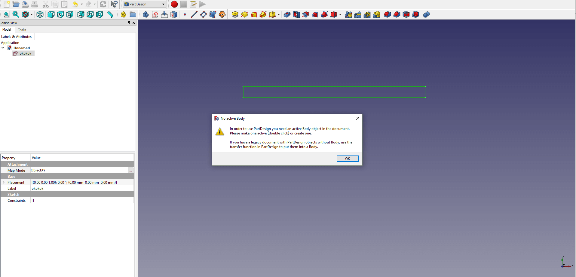
I take a lot of time to figure what's happen and why I didn't success to extrude.
So Google was my best friend 🚀 and apparently they are a bug in freecad and you nedd to start a sketch in the view Part Design.
To have a better navigation, especially for me, I like to use just my laptop, so I configure the navigation mode to the Touchpad navigation. So I can move arround the object by clicking on alt and moving the track pad.
To see more please go to the official documentation
After all, I made this fist model:
Result render
Here, we have the final renderer, you can move the 3d model with your mouse
'
Files
What I'm thinking about it
Actually, I have a lot of trouble to clone objects and and to draw in the reality my Conveyor belt.
It's hard to learn how to use the software and to imagine the final project. I need to make some thing simple and upgrade it after.
I need to practice more in freecad, and comeback on it with mature idea and sketchs. But, above I have made a conclusion with the good points and bad points for me of openscad.
Good points
- Many navigation modes
- Lot of tutorials
- Possibility to write python scripts (need to explore more)
- OpenScad compatibility (need to explore more)
- Opensource
Bad points
- I don't understand how make strategy for the cloning
- Lot of modes (
Part design,Sketching, ...), it can be confusing - Error not always explicit
Fusion 360
Let's try
I had a little experience in Fusion 360, so I start to produce something quickly.
My fist step was to drawing what I have done in FreeCad. For me, the 2d mode was clearly more user friendly than freecad.
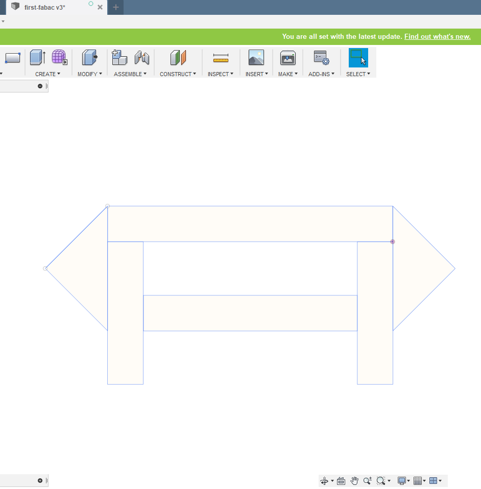
I have extrude the all thing, no without problem, otherwise it would not be funny 😅
I try to use the clonage to extrude one time for two sketch, but I had a lot of problem, I did'nt find a way to do it, so I did it manually. After that, I made clone with symetry (not in the best way, I think) of all the first structure and move it in the axe X.
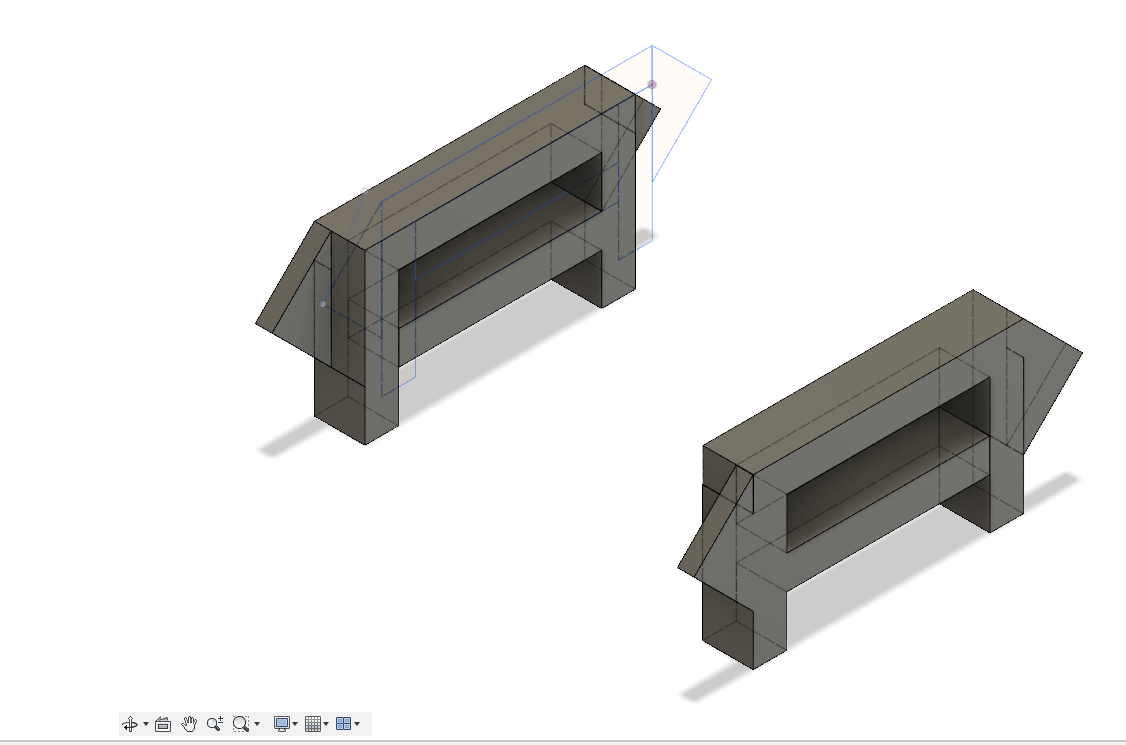
I adjust the position X of clone to have them exactly aligned in the front.
After that I made sketch in the surface of my clone to make a cylinder between the part. I try to clone the cylinder to use it in the other extremity of my object, but unfortunately, I did'nt find the way. So I did it manually 💪
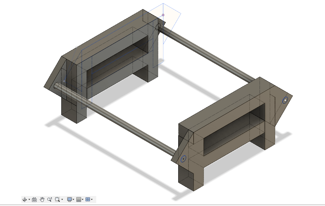
I try to made bigger cylinder over the first cylinder, but I did'nt find the way, I think I need to see more tutorials 😓
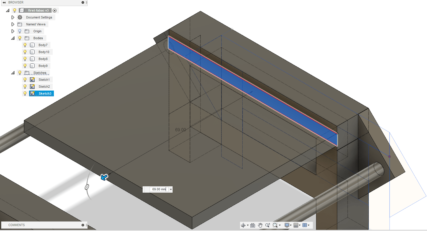
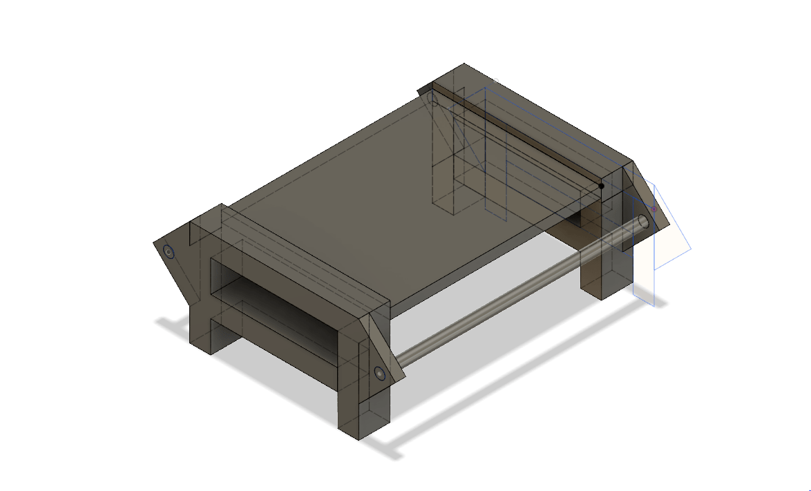
Result render
Here, we have the final renderer, you can move the 3d model with your mouse
'
Files
What I'm thinking about it
It's look more user friendly then freecad, but fusion 360 has also his defaults. It was hard for me to navigate correctly with the trackpad, and I have insisted. I need to have more knowledge about cloning and constraints to be able to produce greats models.
Good points
- Easy friendly 2d mode
- Lot of tutorials
- Possibility to write python scripts (need to explore more)
- Many modes and explicit for each of mode (need to explore more)
Bad points
- I don't understand how make strategy for the cloning
- Lot of modes (
Part design,Sketching, ...), it can be confusing - No navigation specific for trackpad
OpenScad
Setup
- Go to the official website
- Download openscad for your system
- Launch it 🚀
Let's try
I had a litte experience before in OpenScad, so I was already familiar with the language and I have understand the basics functions.
But before starting, I follow few tutorials to get the best practices.
After this tutorials, I get the follow strategy, make small parts in modules, and like spiral project developpment, upgrade more and more.
So I start, by making a module foot of my conveyor belt without parameter, my goal, was to test functions of openscad. When I was ok with my foot, I fixed the size of $length $width and $thickness, and I made all the other parts in functions of this values.
Stupid error
I used this script to optimize my images, but it's to much, and I didn't save the original screenshot 😦
magick mogrify -path .\images\ -resize 300 *.jpg
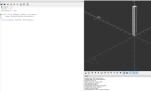
Side:
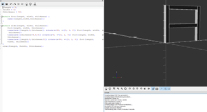
Structure:
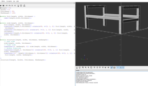
Conveyor Belt:
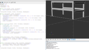
This is my final script for this test with openscad:
$length = 5;
$width = 5;
$thickness = 50;
$bedLength = 100;

module foot(length, width, thickness) {
    cube([length,width,thickness]);
}
conveyorBelt($length, $width, $thickness, $bedLength);

module side(length, width, thickness){
    foot(length, width, thickness);
    translate([length,0,thickness])
        rotate(a=90, v=[0, 1, 0])
        foot(length, width, thickness);
    translate([thickness+5,0,0])
        rotate(a=0, v=[0, 1, 0])
        foot(length, width, thickness);
    translate([length,0,thickness/2])
        rotate(a=90, v=[0, 1, 0])
        foot(length, width, thickness);
}

module structure(length, width, thickness, bedLength){
    // Left side
    side(length, width, thickness);
    // Right side
    translate([0, bedLength, 0])
        side(length, width, thickness);
    // Middle fixations
    translate([length,0, thickness/2])
        rotate(a=180, v=[0, 1, 1])
        foot(length, width, bedLength);
    translate([(2 * length)+thickness,0, thickness/2])
        rotate(a=180, v=[0, 1, 1])
        foot(length, width, bedLength);

}

module bed(length, width, thickness, bedLength){
    structure(length, width, thickness, bedLength);
    translate([0, 0, thickness])
        cube([(2 * length)+thickness,bedLength+width,length]);
}

module conveyorBelt(length, width, thickness, bedLength){
    structure($length, $width, $thickness, $bedLength);
    bed($length, $width, $thickness, $bedLength);
}

conveyorBelt($length, $width, $thickness, $bedLength);
Result
And bellow, we have the final renderer, you can move the 3d model with your mouse or download the file by clicking juste here
'
What I'm thinking about it
Good points
- Easy to use
- Many tutorials
- Easy cloning and add parameter
- Possibility to convert on openjscad (need to explore more)
Bad points
- Need to understand mathematics
- Need to write code (For me it's ok, but I think it can be a problem for non developer)
- Many function to describe small things some times
2D Software
This week i was Really more into 3D software that 2D, i think Inkscape is a great tool for 2D vector, so i made the of my final project with it. It's not the best tool for that. But it free and we can use it for lasercutting so it's good enough. i can import vector line and zoom out watching the result, it's really usefull, I can also add logo text to this vector.
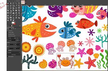
Firstly, I go to Freepik to get some sympatic vizualisations. I download one vizualization that I liked. When you download the project, it's a zipfile containing the license. Because I didn't pay, I need to mention that it was Designed by Anggar3Ind / Freepik, So I will take this base to make my logo.
Because I'm using windows, and eps extensions does'nt work natively. I install Ghostscript, and I open the eps file with Gimp, selected the cartoon that I choose, copy it (Ctrl+c) and past it (Ctrl+v) on Inksckape.
I add text Fish on the top, and Sitter on the bottom, and in the middle I let the crabe. So after that, I tried some typos and finally, I choose to take the Ravie typo.
After that, I use one of almoast functionnality of Inksckape. I vecotrize the picture of the crabe. To do that, I select the crabe, I clicked on Path > Trace Bitmap ...
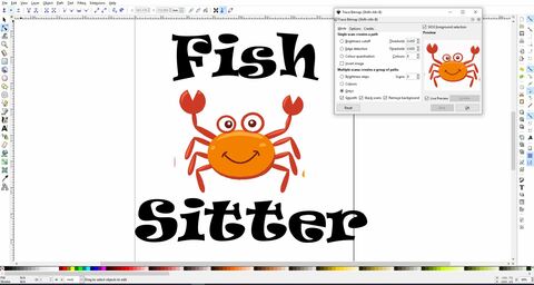
I didn't know what are all the options, but after some tests, I chose the above configuration. Once, the picture was vertorized I remove the undesireable parts by selecting points and clicking on Suppr.
An then I adapt the document to my design and I applied margin of 5mm on each side like you can see there.
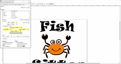
And then I export the png by using the function under File > Export PNG Image, and then I choose dimensions that I needed.
So this is the final result:

Downloads files
What's next ?
- Try to generate my model with python
- Get more knowledge about cloning and the differents ways to made more materials in cad software
- Take a decision between Freecad, Fusion360 or other software !
- Learn how to simulate objects