7. Electronics design
This week I drew, made and programmed my first board; I redrew, milled, soldered and programmed the hello board, adding more components. I added a crystal, a LED and a switch button and two more resistors and capacitors.
CAD
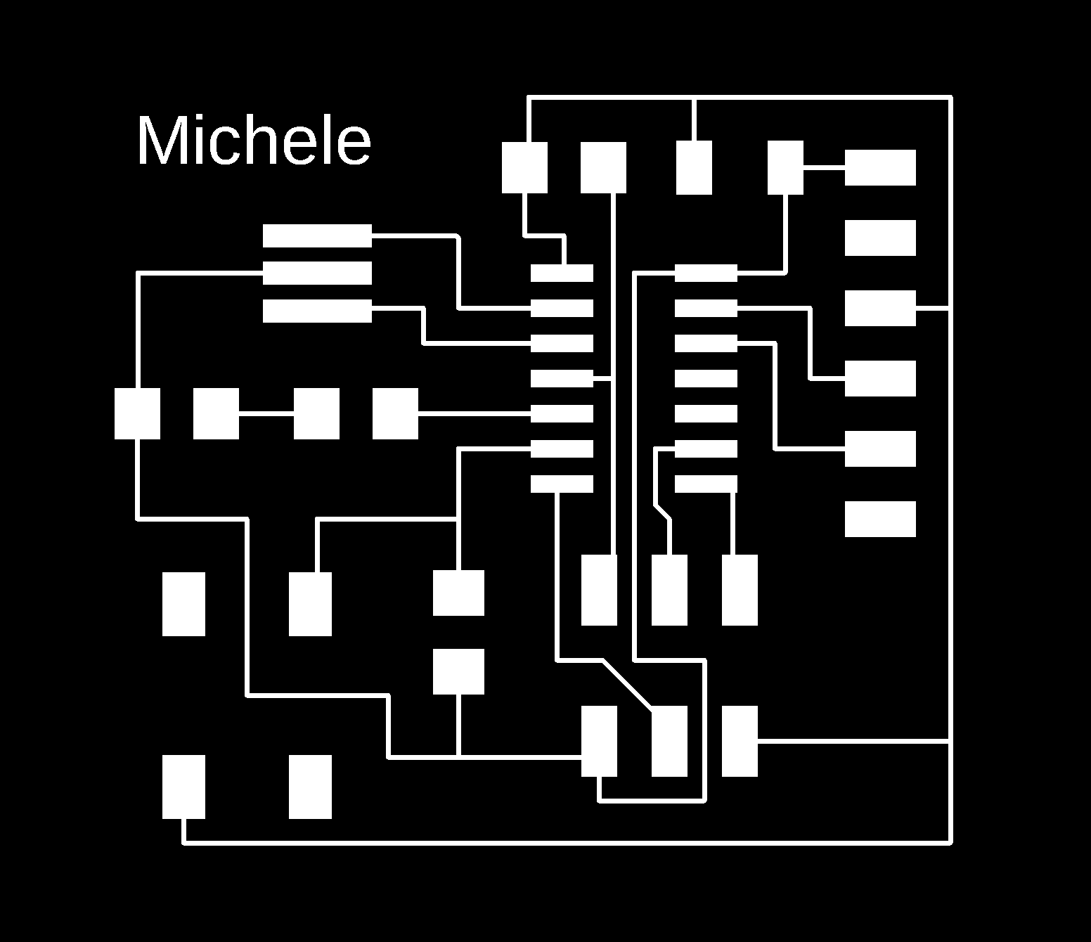
I drew the traces and outline of my board using Eagle CAD software, then I exported them and completed my board.
Eagle
I worked using Eagle. So step by step I downloaded the library of the electronic components on GitLab, I connected them first in the Schematic workbench and then in the Board workbench.
Downloading the library
1st On git lab I selected eagle library and 2nd downloaded a full library of supported file components.
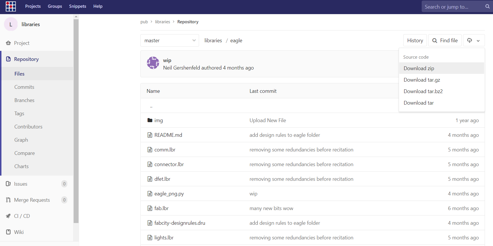
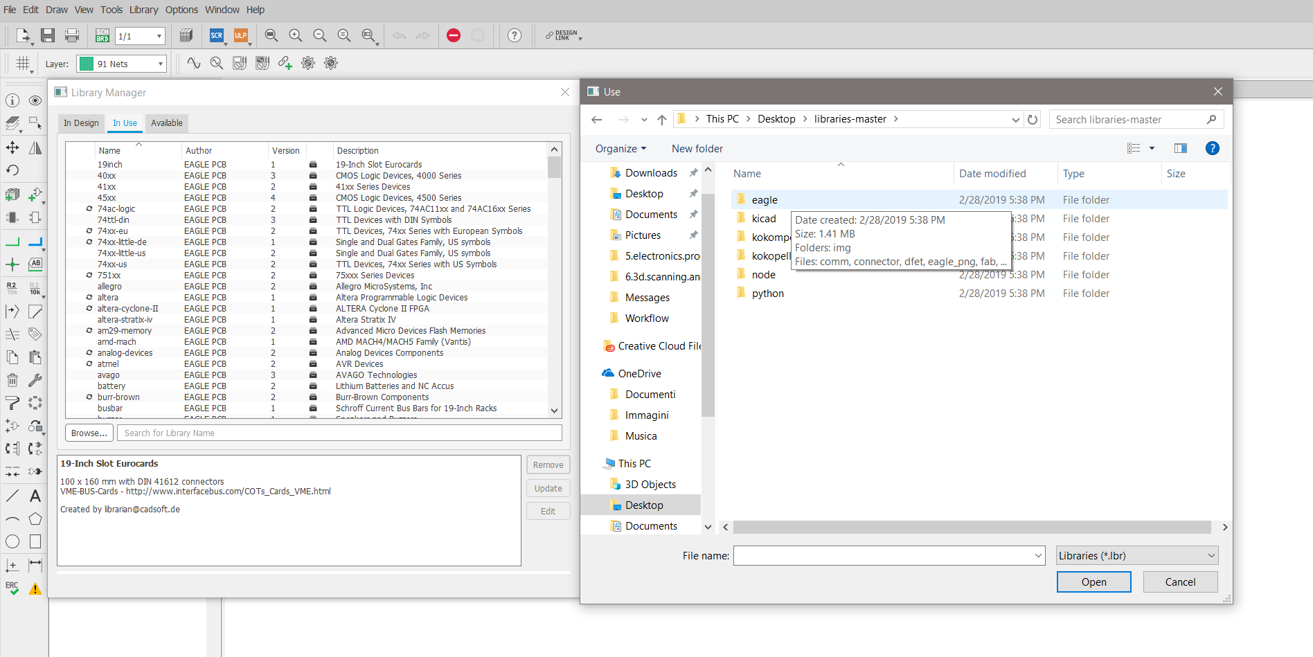
3rd In Eagle software I opened my library manager and I uploaded it.
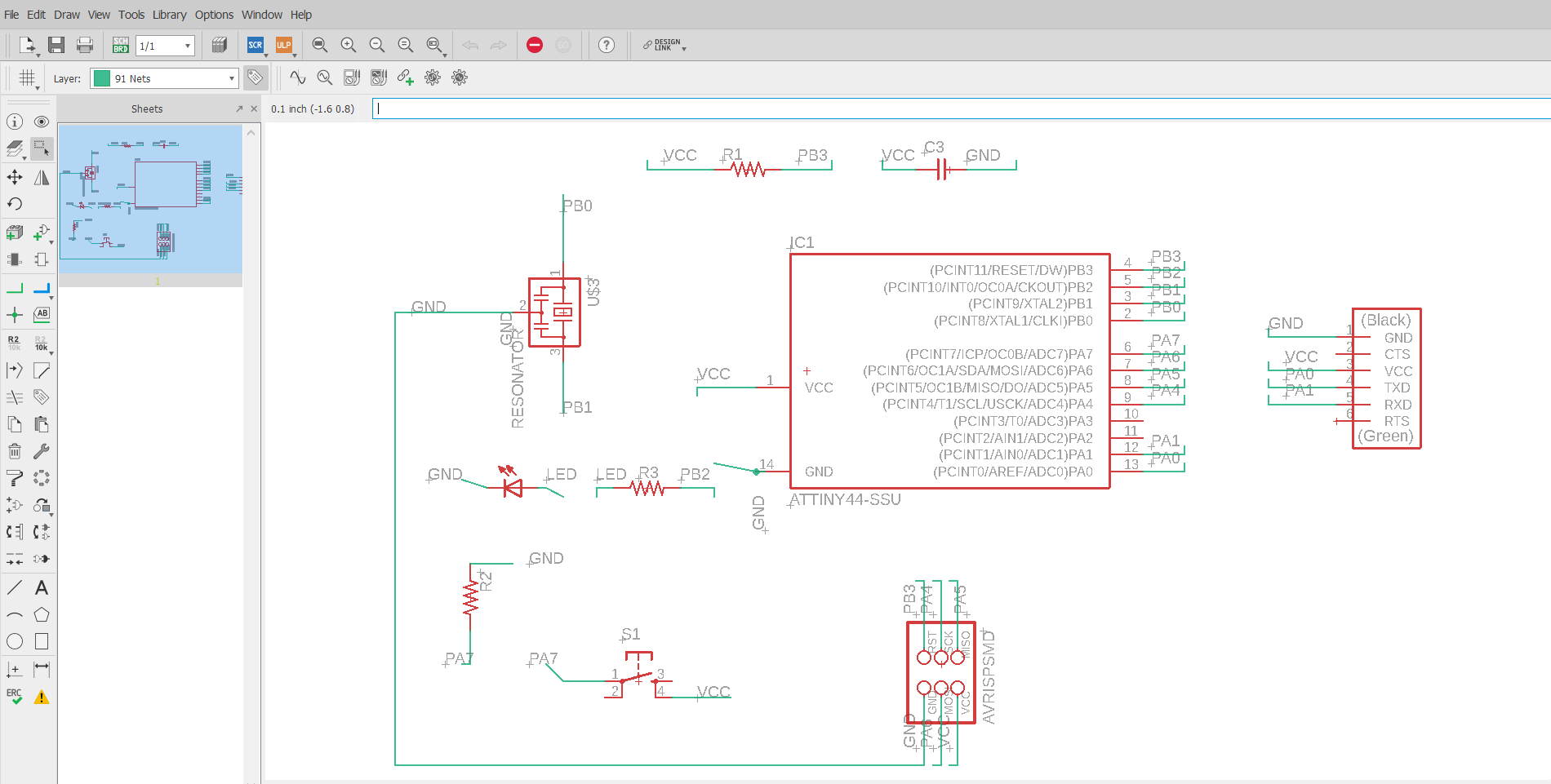
Schematic workbench
I started uploading the necessary components in my project. 1st I added the electronic components clicking “add” and 2nd I connected them drawing ‘’nets’‘ and respectively noting the connections with the command ‘name’ according to the standard hello board.
I added a switch button and connected to a free pin of my attiny 44 and to VCC, and one led and resistor.
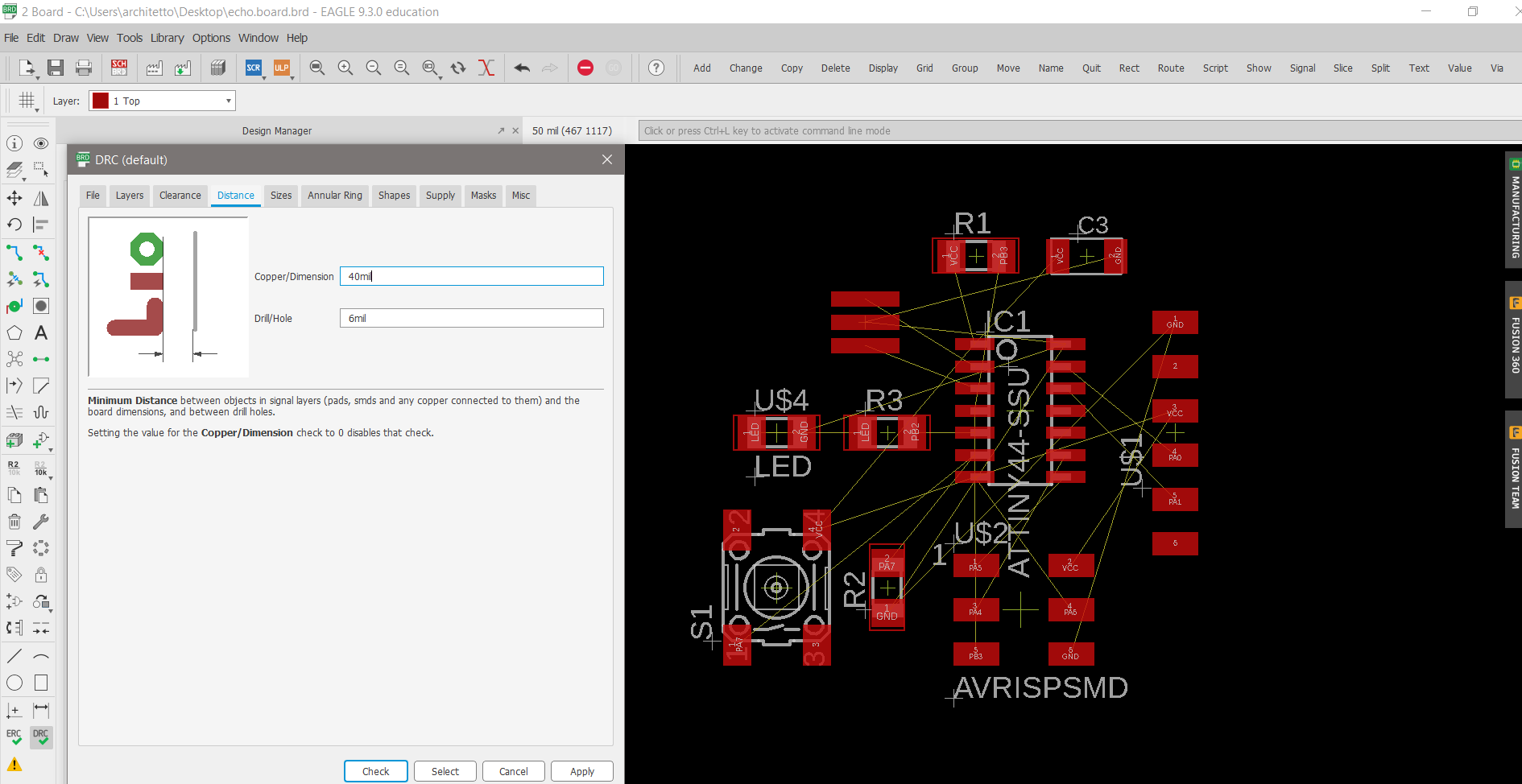
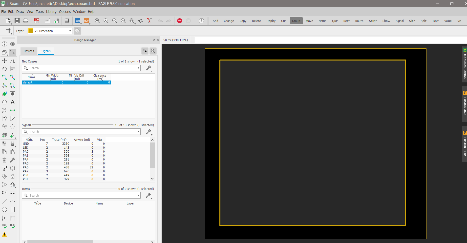
Board workbench
1st I switched the project to the Board workbench and 2nd in the design rules window (DRC) I set all the features of the traces of my board, such as distances and size.
3rd In the left corner of the page I set the “top” layer 4th and manually I respectively drew traces to connect components, using “route” command and simultaneously with alt command, moving them with accuracy.
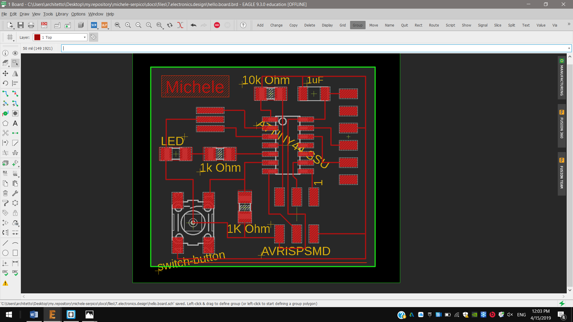
5th And then I switched to the “dimension” to draw the outline of my board.
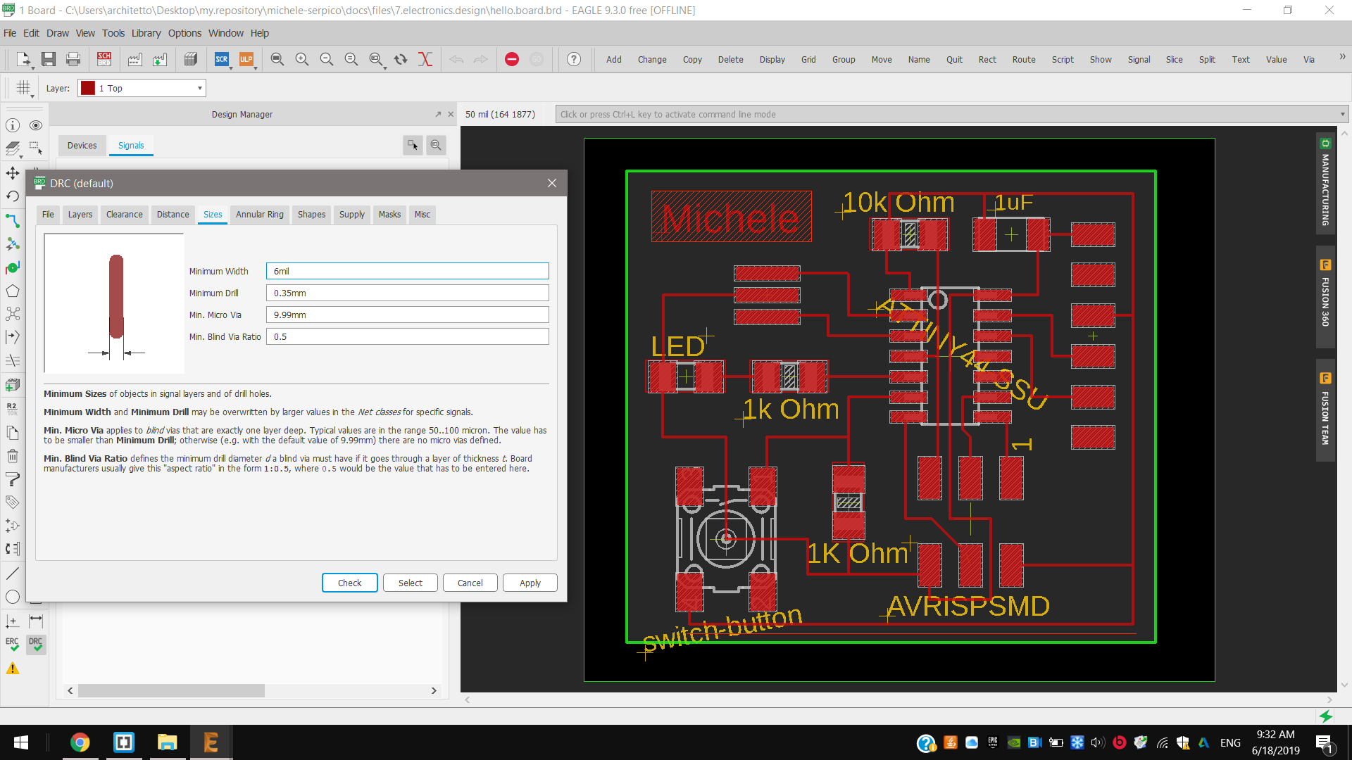
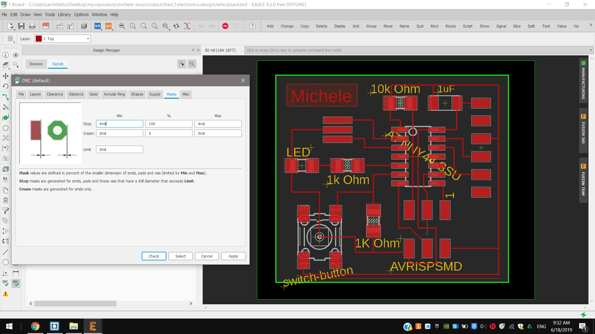
And I set all design paramters on the the DRC window; I set a size of traces about 6mil and a minimum distance between them about 40mil. I could also set other deep automatic functions in the “Misc” window, to check fonts, masks and more.

So at the end I verified my project through ERC command and it gave me no errors.

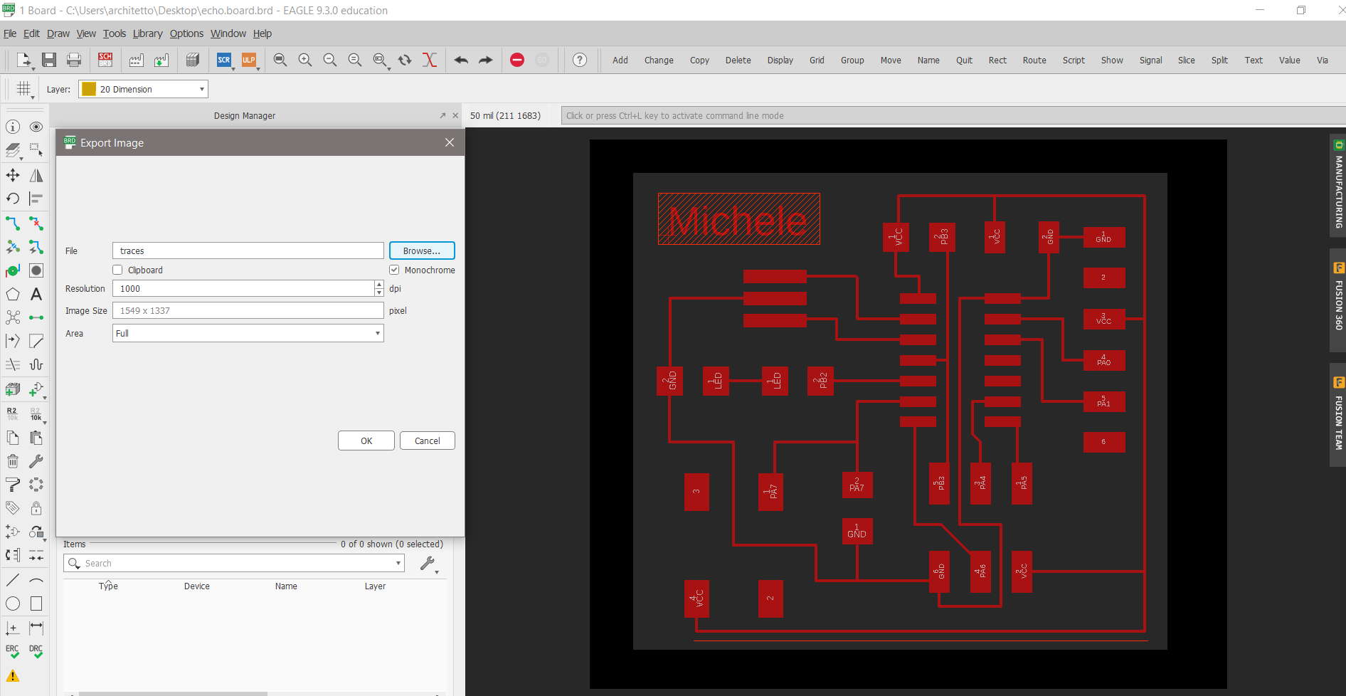
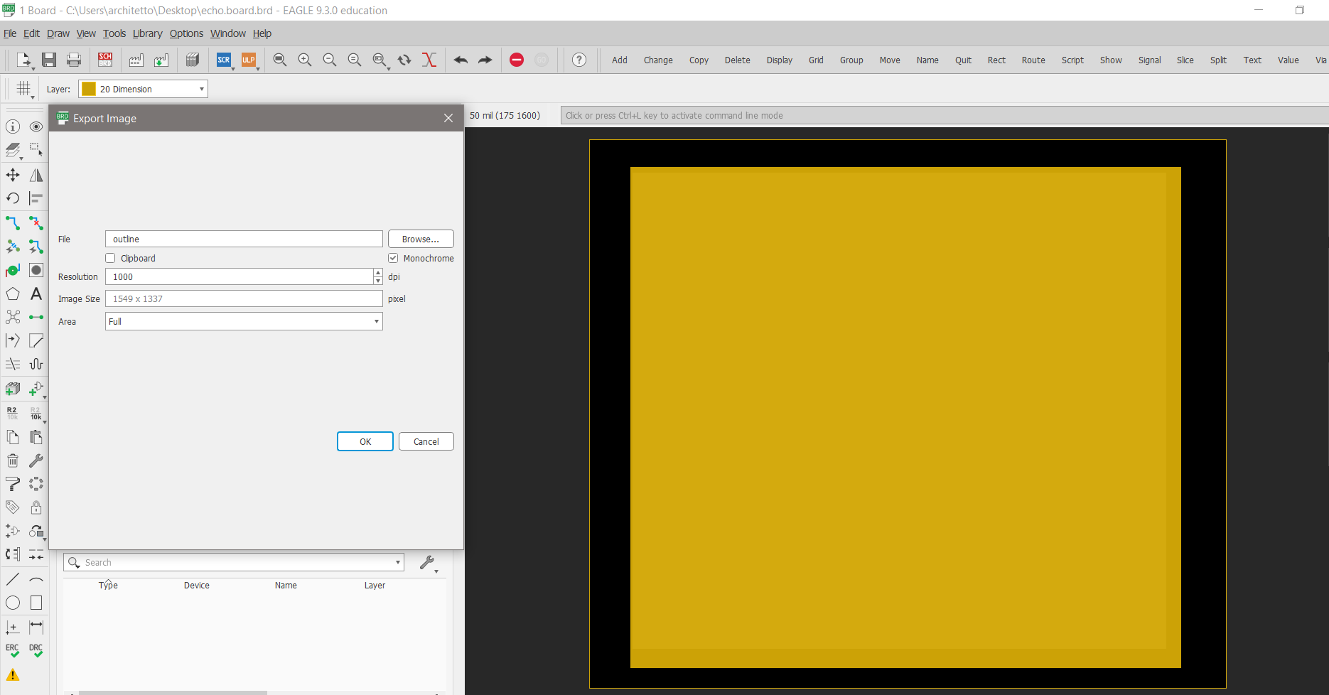
Exporting
Then, respectively, I exported these traces and this outline in 1000 dpi png files and monochromatic color, generating the png files.
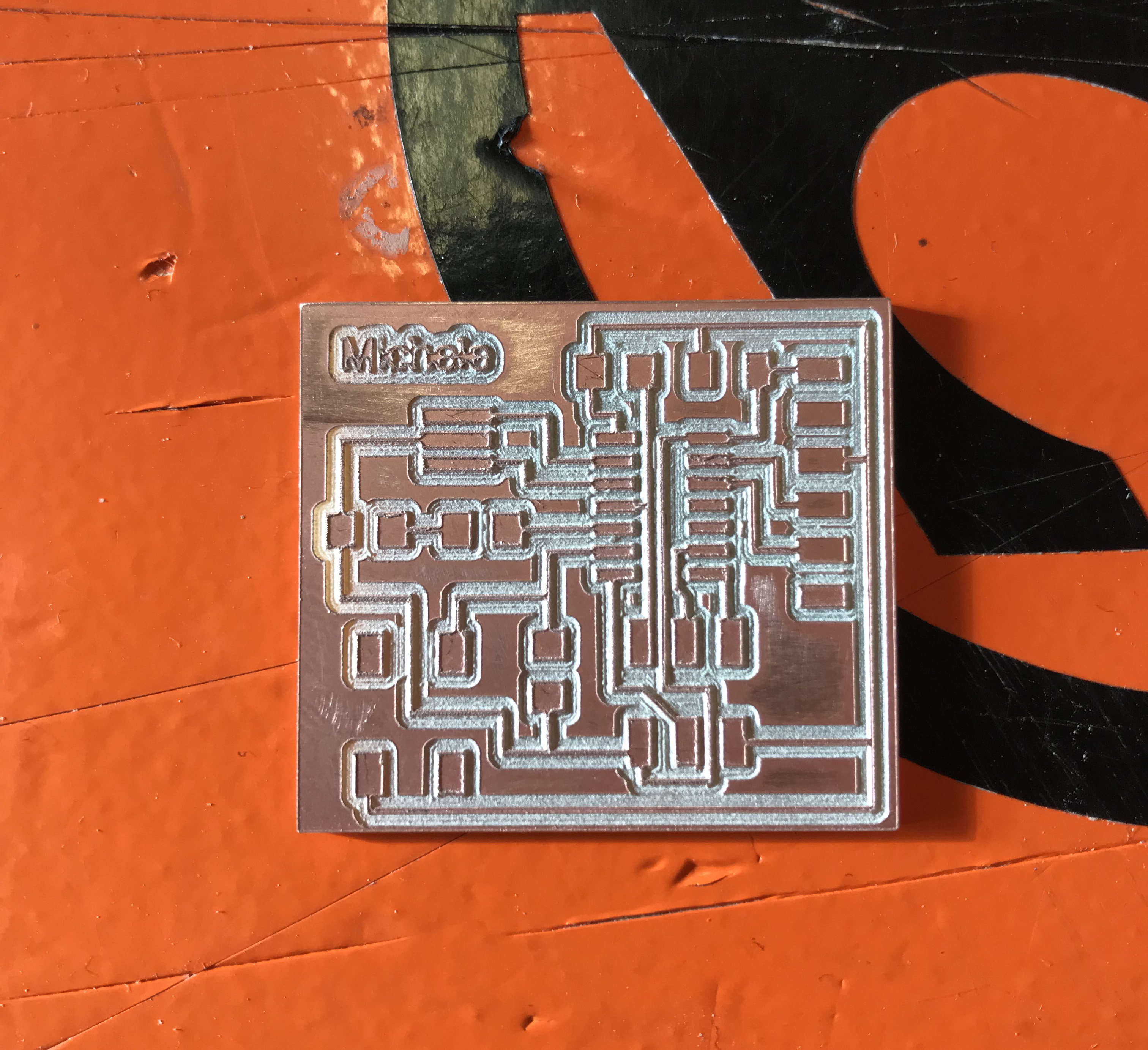
Milling
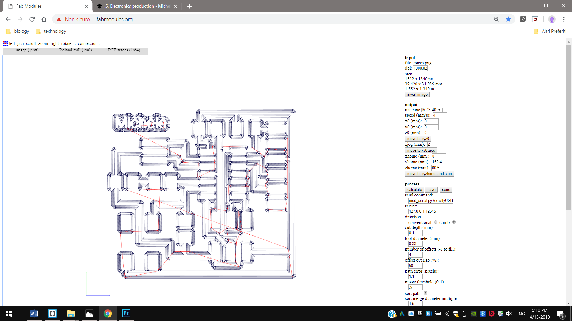
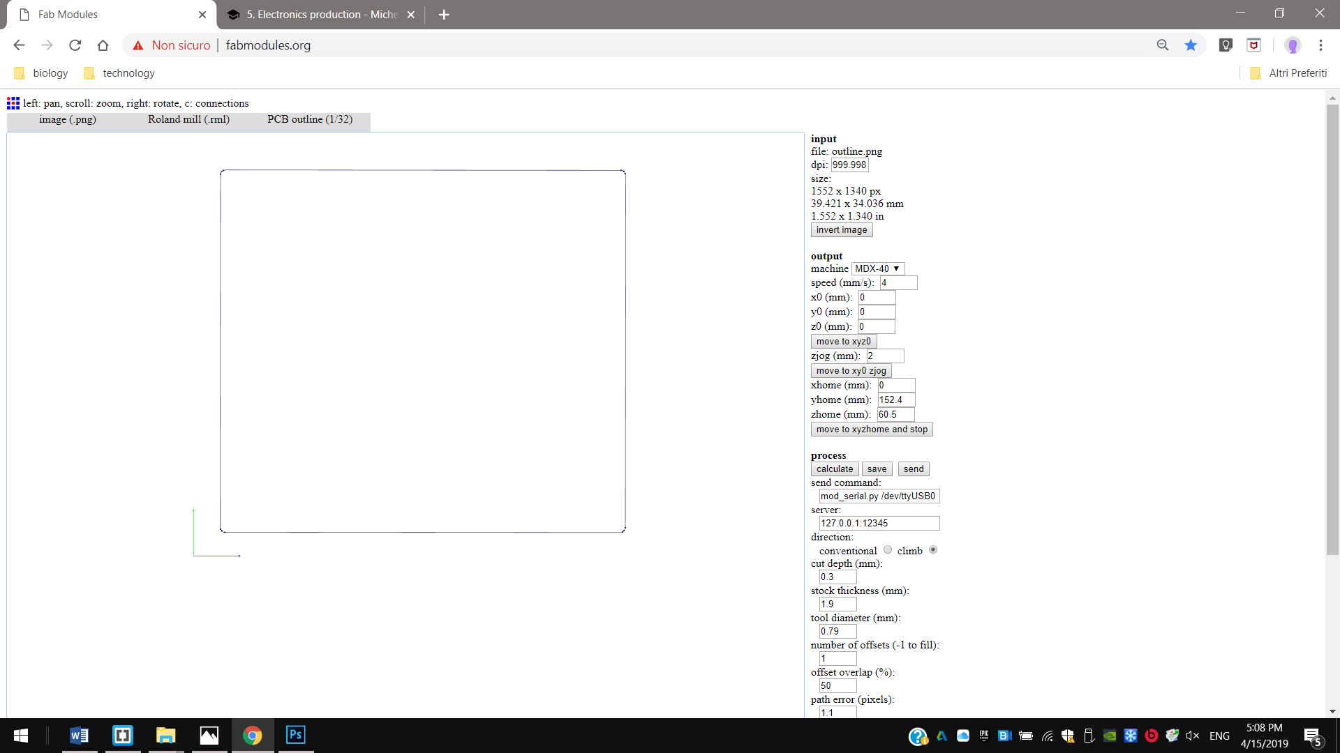
Fab modules
1st I generated .rml traces and .rml outline using Fab Modules. First I set a milling size of 1/64’‘ and a cut depth of 0,1 mm to make the traces, with 4 offsets.
2nd And to mill the outline instead I set a milling size of 1/32’‘, a cut depth of 0,3 mm for each step for the whole thickness of 1,7 mm. I set 4 milling offset both times.
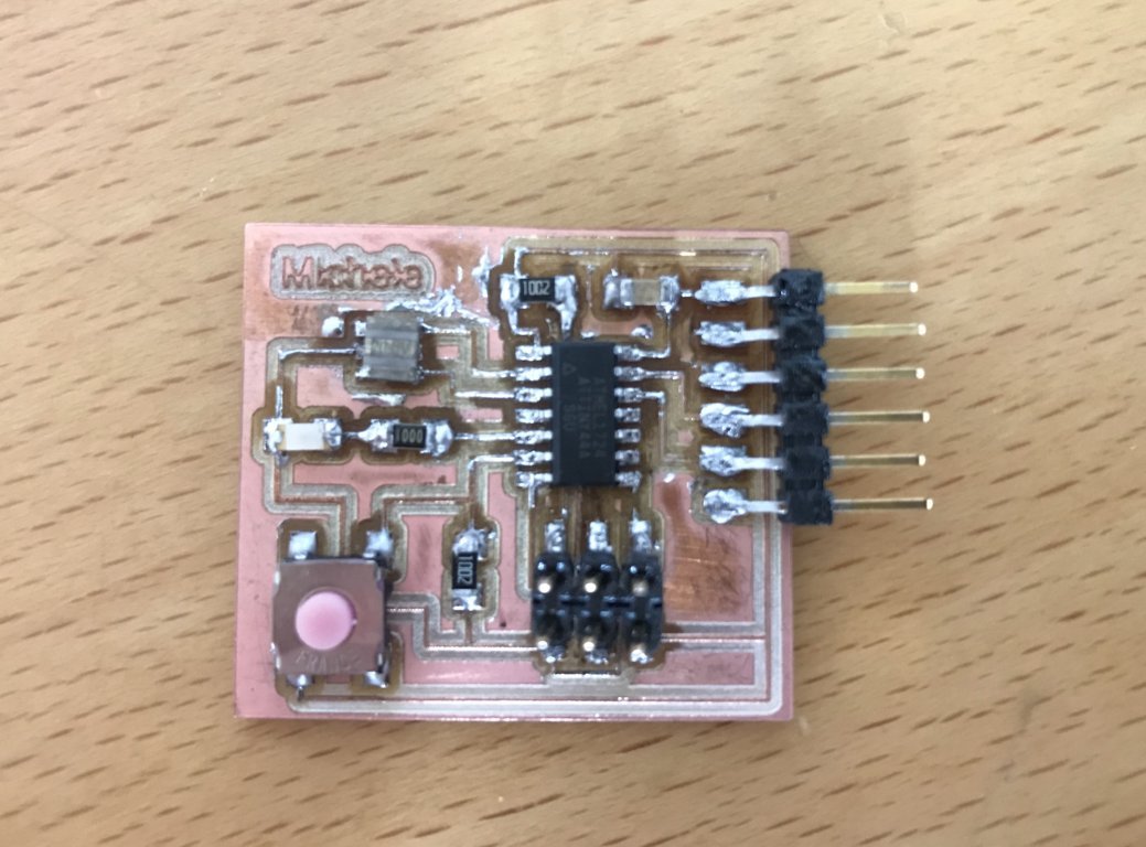
Soldering
I soldered this hello board with this components:
- 1x Attiny44
- 1x resonator 20MHz
- 1x 1K Ohm + 2x 10K Ohm resistors
- 1x 1uF capacitor
- 1x green LED
- 1x ISP connector
- 1x FTDI connector
- 1x 5V switch button
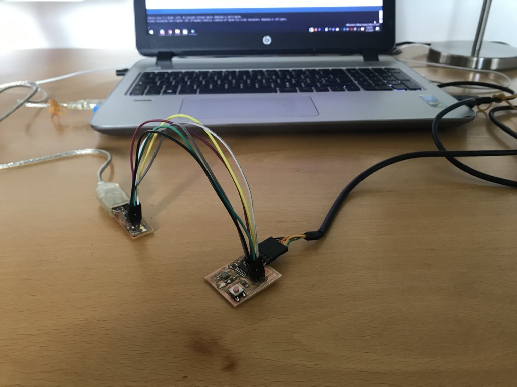
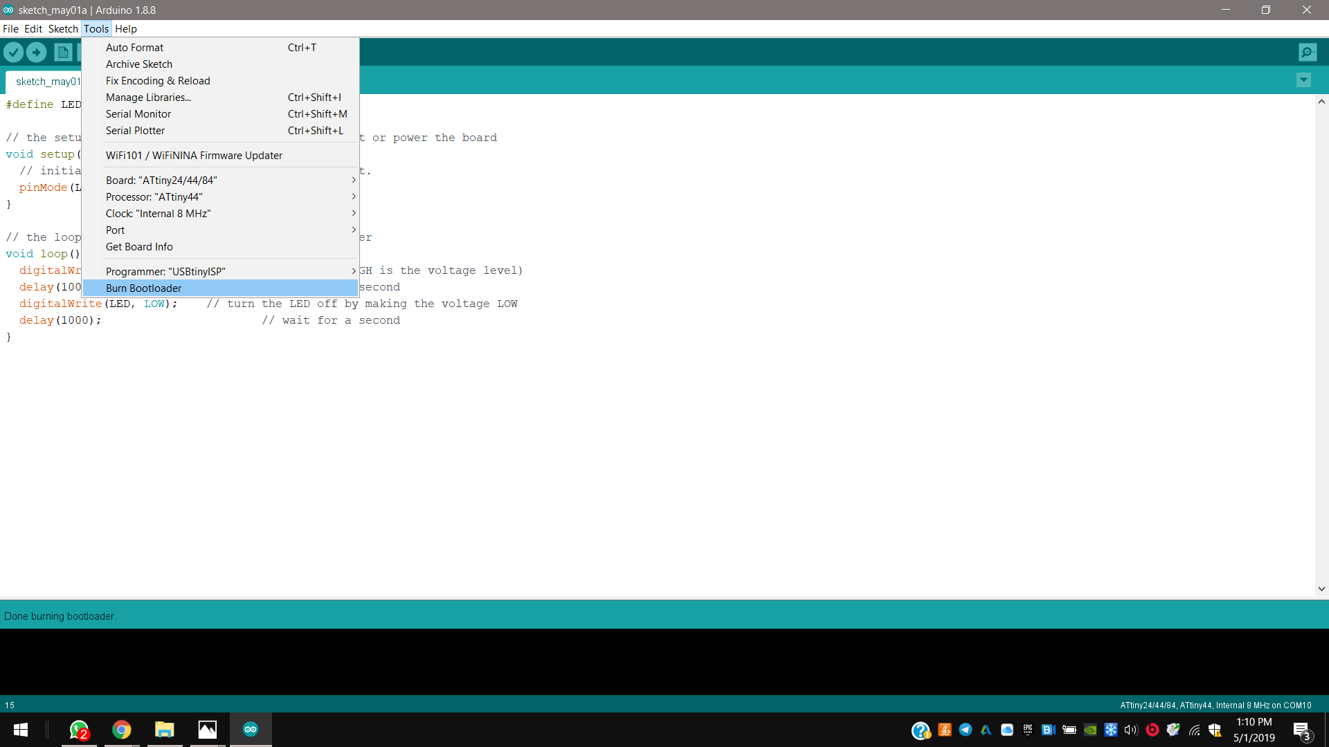
Programming
And after I programmed my board to turn on/off its LED.
I programmed it with the lower 8MHz internal clock frequency, because my resonator didn’t work.
I start connecting it to respectives VCC, GND, MISO, MOSI, RST and SCK of my USBTinyISP.
On Arduino IDE, in “tools”, I selected USBtinyISP programmer, and respective port and clock. I burnt the bootloader to program fuses memory, and I tested it uploading a simple blink code.
Downloads
.sch
hello.board.plus.button.led.sch
.brd
hello.board.plus.button.led.brd
.png
traces
hello.board.plus.button.led.traces.png
outline
hello.board.plus.button.led.outline.png
.rml
traces
hello.board.plus.button.led.traces.rml