
Week 11. Input devices
27.03.19 Class
This week the sensors finally touch, sensors that will measure some kind of information of the medium, also called inputs. During the class you will tour the different sensors that exist. It also explains how to program them to get the signal graphically through the terminal.
And from there we started to see the different types of sensors, such as the presence sensor, the photoresistor, the accelerometer, the sound meter, etc. we have to have already clear our final project to start focusing this type of assignments to choose the sensors that we will use in our final projects.
Week planification
This week he returns to play electronic and programming, at the same time I have a change of work and I go from working in the Fablab of Nebrija to working in the fablab of Esne.
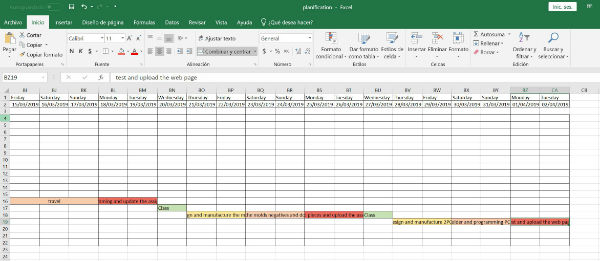
For Thursday and Friday I want to develop the designs of two different plates with different inputs and that I have time to mill both to be able to weld during the weekend.
Saturday and Sunday I want to take the opportunity to weld these plates with their components and start programming them to get all the information on Monday and upload it to the website.
Group assignment
I'm waiting to join the rest of my colleagues from the remote fabacademy to do it all together in one of our fablabs.
The time has come to get together and we have decided to measure the signals of two of our plates, on the one hand, as a digital signal we have selected the hello board that we developed for the week of embedded programming and as an analog signal we have decided to measure the signal that transmits us the phototransistor that we created this week. We have been able to do this since the groupal assignment we did weeks later to perform the individual assignment.
First we have loaded the blink program on the hello board so that the led flashes and we have tested the oscilloscope of our companion elena but we have not managed to work since it gave us strange signals and we have not been able to make it work well. Then we used my DIY oscilloscope that I bought for ebay for € 17 (purchase link) and I had to assemble and weld myself, we have made it work, then we see the video that shows it and where we can see the digital signals of the blink program that we have loaded on the hello board.
Then we have loaded the signal program into the phototransistor and we have also measured the signals that it emitted, in this case analog signals which oscillate. Next I show a video in which the test is seen.
Individual assignment
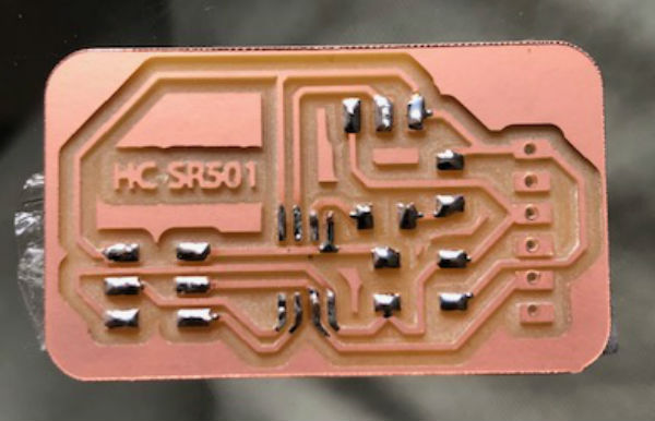
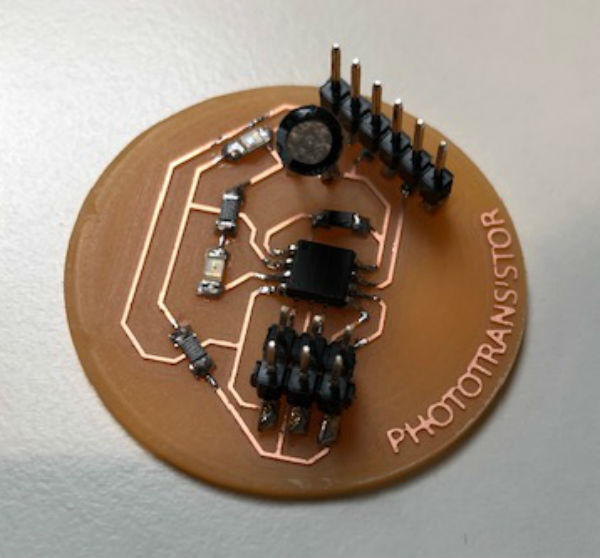
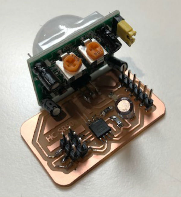
For the individual assignment I decided to make two plates with two different inputs, for the first I decided to put a motion sensor HC-SR501 and for the second plate I decided to mount a phototransistor.
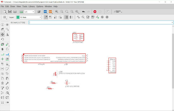
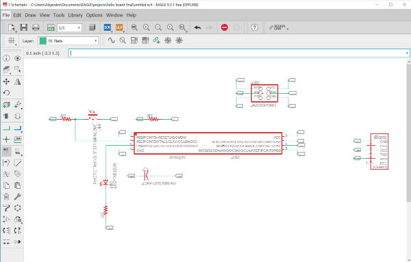
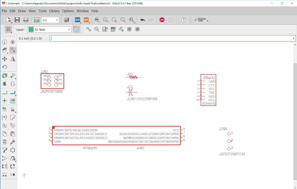
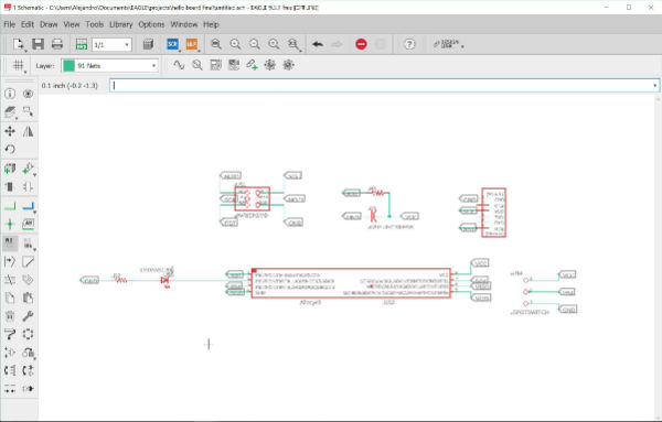
Through Eagle I designed both plates, both with the Attiny45, but also in my design, as I have one pin, I added an LED with its corresponding resistance to each of the plates to be able to emit a signal with the signal of input of each of the sensors.
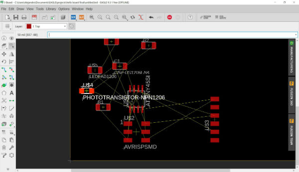
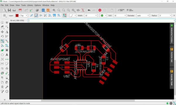
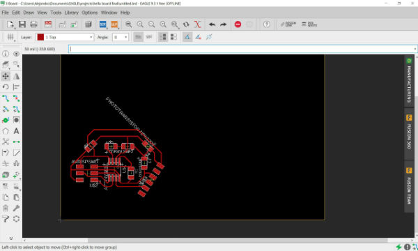
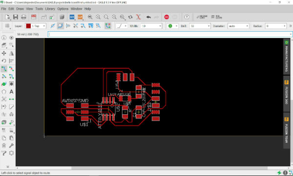
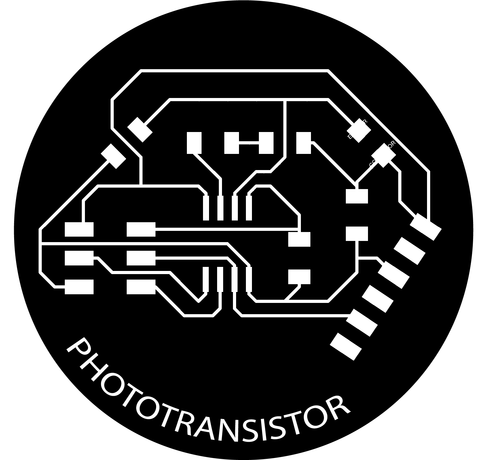
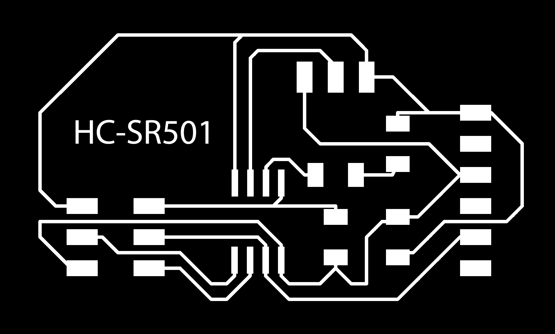
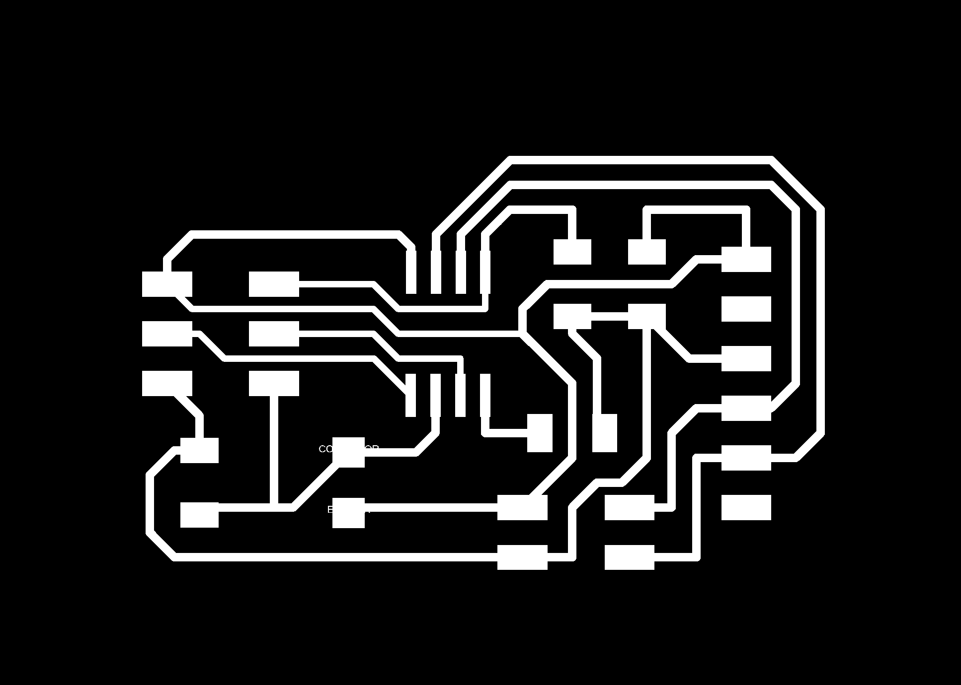
With these plates designed, I have exported them in PNG, color monochrome and I have followed the same steps as in the electronics production assignment. The final result for my plates is as follows:


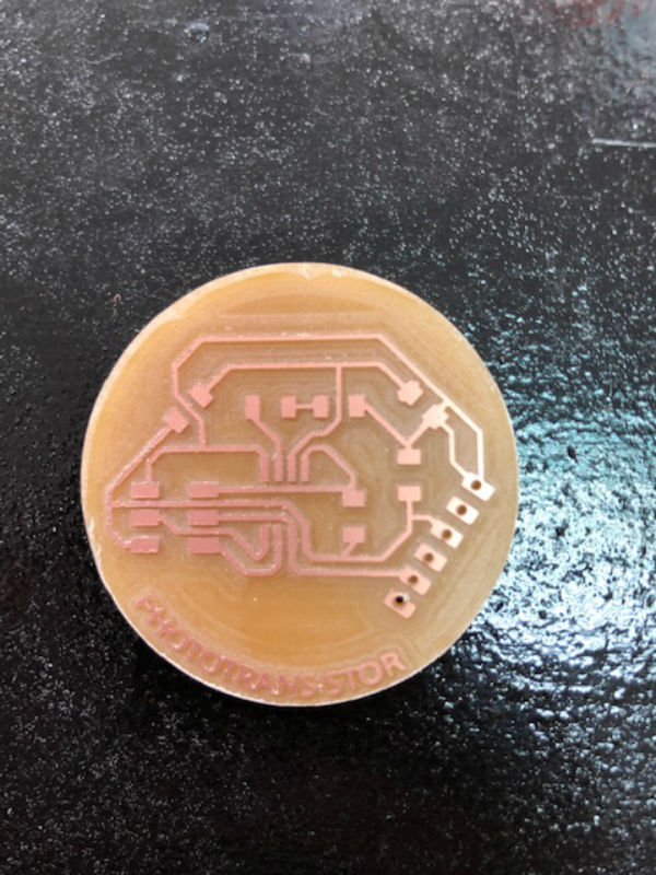
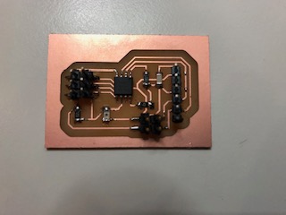
I have followed the same steps to mill the plates that in the assignment mentioned before and I have managed to get these plates.
PHOTOTRANSISTOR:
1x Attiny45
1x AVRISPSMD
1x 1X06SMD (FTDI)
1x 10kΩ resistance
1x 1µF capacitor
1x Green led
1x 499Ω resistance
1x PhototransistorSMD
HC-SR501:
1x Attiny45
1x AVRISPSMD
1x 1X06SMD (FTDI)
1x SPDTSWITCH (HC-SR501 SWITCH)
1x 10kΩ resistance
1x 1µF capacitor
1x Green led
1x 499Ω resistance
1x HC-SR501 sensor
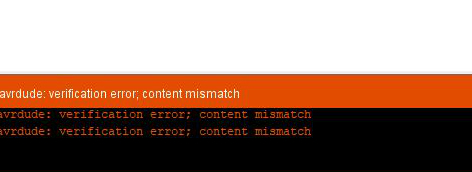
After this I start programming the phototransistor board, I burn the bootloader well, the program compiles it perfectly, but when I upload it to the board I get the following error: avrdude verification error; content mismatch.
 I have changed the programmer to use from the Arduino program and now it has been left with a new error, or a new problem:
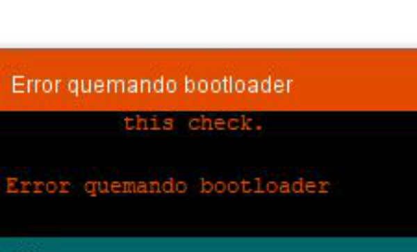
I realized that I have not burned the bootloader, I burn it with the change made by the programmer and I get an error when burning the bootloader.
 Elena, my colleague, suggests that I change the FTDI cable COM port, I do it and again it recognizes me again and allows me to burn the bootloader.
I upload the program, upload it correctly, but when I open the serial monitor I have it blank again and I do not receive the signal from the board.
Program change and copy just like my partner Elena, changing the pins that I used in my attiny45. I burn the bootloader again and upload this program. It gets up correctly but when I open the serial monitor I do not receive the signal.
I decide to desolder the led and its resistance that I added in the remaining pin of the attiny in case it makes some short or strange communication and I repeat the process again, I burn the bootloader, I upload the program and I do not get a signal through the serial monitor.
After this I decide to try to solder another phototransistor and it does not work either, I try different FTDI cables, different FABtinyISP programmers, different programs, but I do not achieve anything.
I decide to rest a little to put the ideas in order and not to work in vain.
 I meet with my instructor Nuria and several of my colleagues by videoconference to discuss and try to reach a solution to my problem. The first thing we see is that my computer has disabled the USB ports so much connecting and disconnecting things, therefore, it is not recognizing any device. This is solved by restarting the computer and in this way the USB ports are enabled again. We check it by connecting the programmer and we see that it recognizes it.
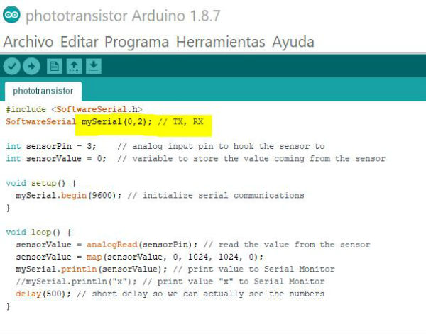
Then we have to solve the problem because it does not open the serial monitor and recognizes the data collected by the phototransistor and we attribute this problem to the fact that in the program the pins for which RX and TX will receive are not inserted correctly in the header. therefore we try different combinations until we find the correct one: TX, RX (0,2).
 Finally it works, then I put a video in which you see the serial receiving the data captured by the phototransistor.
With the HC-SR501 sensor I have had problems and it has not worked at any time, so I have left it for some time that has time and I will review it well to make it work.
On the other hand, 1 month after completing this assignment, I need to do the assignment of networking and communication. for this I need an input with BUS, I do not use the phototransistor that I already have with 4 cables soldered to the tracks or using FTDI shots.
For this I have made a new phototransistor board with BUS line to communicate it with my output. Below I show the boards:
 Once designed, I mill and soldered the necessary components to make it work.
 I connect my new sensor through the FTDI and the flat cable to my computer and my programmer. I take the program that I use for my other phototransistor (without bus) and change the TX and RX pins to 3 and 4 and also the sensor pin to number 1. I upload my program and check that it works through the serial monitor. In the following video you can see the new operation.
My files
Phototransistor board
Phototransistor schematic
Phototransistor program
HC-SR501 board
HC-SR501 schematic
Phototransistor BUS board
Phototransistor BUS schematic
Conclusions
As you can see the presence sensor I have not programmed it since I have had many problems with the IR sensor and this I have finished the week of the outputs and to not delay more I decided to leave it for later when I have more time, plus the presence sensor also gave me problems therefore I will need time also to determine what the problem is and be able to put it to work. On the other hand I am working on a flight time sensor to measure distance which is the one I want to introduce in my final project and this is taking me a little bit of time on the other hand.