
Week 07. Electronics design
27.02.19 Class
During this class we have seen everything related to electronic design, the different programs that help to work on the designs, also where we can find the libraries and design rules related to the Fabacademy.
Week planification
As every week I have planned the tasks to be done during this as follows:
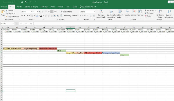
On Thursday afternoon we have the local review and it will show how each week the assignment to develop. After this review I will start with a program that I usually use for electronic design called fritzing and with it I will try to create the pcb HELLO BOARD. Then I will try other programs like kicad or Eagle.
On Friday I will leave it to mill the pcb and prepare the different components that I will need to soldered it.
Saturday and Sunday, with the fablab closed, I will soldered the plate at home and begin to test continuity and see that the entire circuit is closed.
Monday and Tuesday I will reserve them to program the pcb with an example program and I will try to perform the tests with the tester and the oscilloscope and see the signals that emit the different inputs and outputs.
Group assignment
This part of the assignment I will leave for the next week, because with the problems I have had this week and I will comment below, I have not had time to do it.
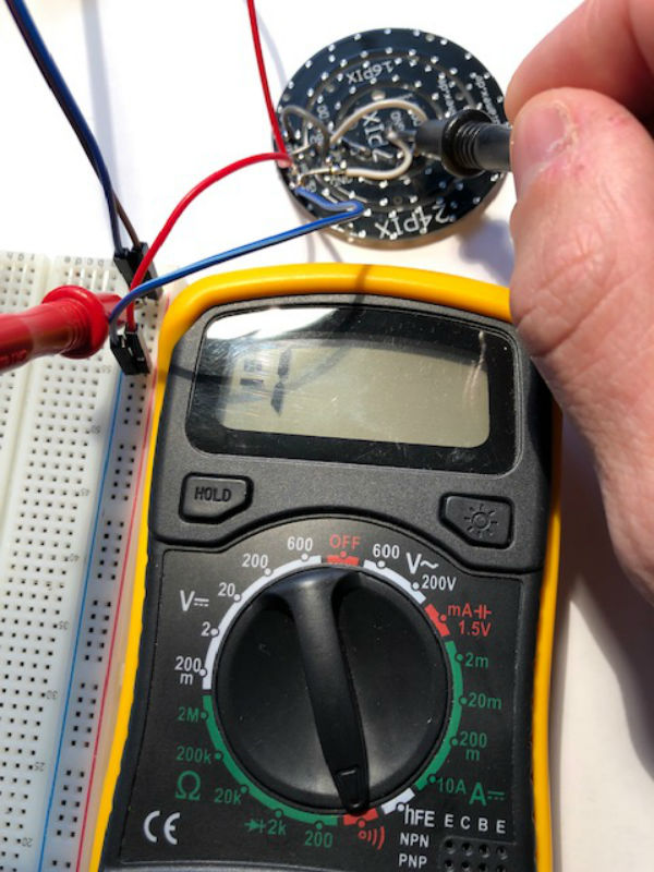
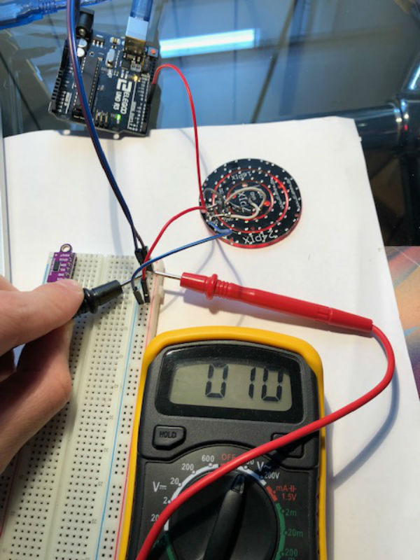
After several weeks, during this week of rest I return to the assignments that I have been leaving to do. This group assignment has been done individually and I have focused on measuring continuity and voltage with my multimeter on some tests that I am doing to an array of neopixel for my final project. In the following pictures you can see both measurements that I have made.
Individual assignment
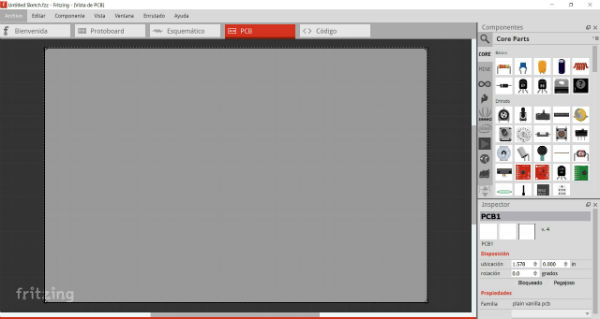
I start the assignment on Thursday after the local review, during this I have been showing my colleagues the fritzing electronic design program, which I usually use to carry out my projects. Within this program there is a part of PCB design, but during the review we realize that there are not the specific libraries that are used for this assignment of the fabacademy, therefore after spending some time searching to see if I can get some libraries specific and not find the solution, I decide to download Eagle and start learning the program from scratch.
On Thursday night I started opening Eagle and started to interact with the different interfaces of the program.
I download the specific libraries of the components for this program: Eagle libraries and I put them in Documents / EAGLE / libraries, in this way the The program has already loaded the fabacademy libraries.
On the other hand, I also download the file. dru (design rules) and placed it in Documents / EAGLE / design rules, with this other incorporation I have the design rules also introduced in the program.
It's already Friday and I do not have the plate designed to mill, I'm late, I open the Eagle with a new project and I'm designing all day and trying to place the components in the schematic file.
The components I open from library / open library ... / and I look for the library in the folder. This is: Eagle_fab.
To introduce them in the schematic of the program what I do from the library is to press the right button on the component that I want to introduce and I give it to add to the schematic. If the component has different variants, they come out to choose the one I want and enter the correct one. This must be taken into account since many components inside the Eagle_fab library are created exclusively for the Fab academy and there are speci fi c components called by the fab pronoun. Once introduced the components we will see them as they appear in the following photos.
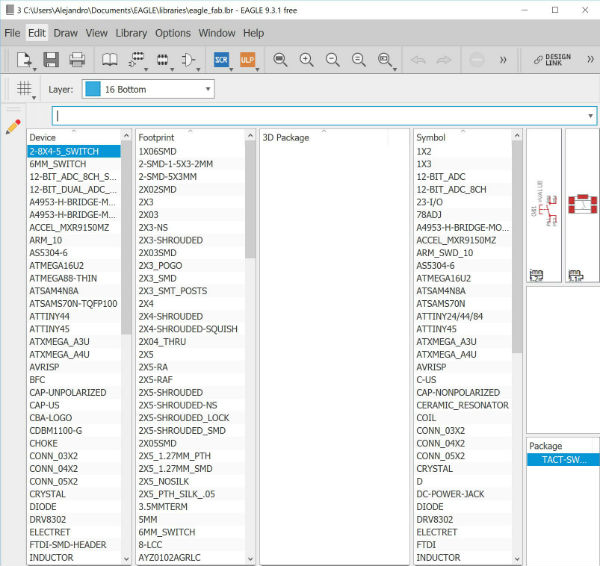
From this library I select the following components that I will need:
Components:
1X ATTINY 44/ SOIC 14
3X RES-US (2x 10k ohm/ 1x 499 ohm)/R1206FAB
1X LED/ LED1206FAB
1X CAP-US/ C1206FAB
1X RESONATOR/ EFOBM
1X 6MM_SWITCH
1X AVRISP/ 2X03SMD
1X FTDI-SMD-HEADER
I do not get the pcb's as I would like and I repeat the placement of the components several times.
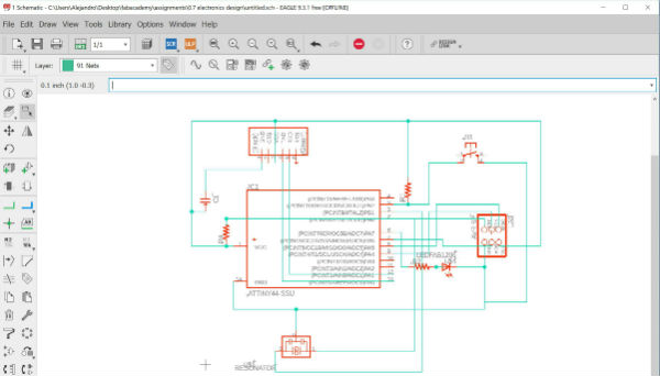
I have spent the time on Friday and I do not have time to mill the board, also to open the ERC option of Eagle I get many warnings and this is because in the circuit that I created in the schematic I am treading multiple tracks.
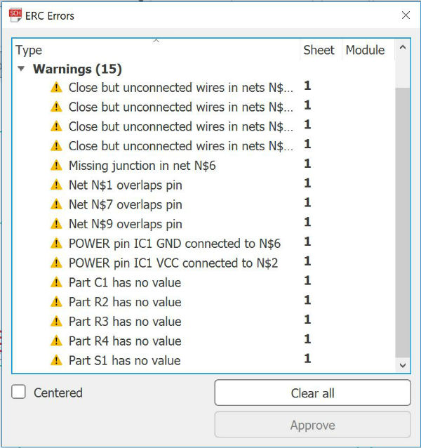
Therefore I decide that I will use the weekend to learn much more about the program, learn to relate the tracks with labels so that the circuit is clean and not stepped on and in this way make a pcb in conditions to not have problems in other pcb's of the future.
During the weekend I learn to make the circuits connecting the tracks by means of labels with the following tutorial:
Eagle tutorial
After doing many tests with the different tools that I have learned, I make my final pcb in the schematic and it looks like this:
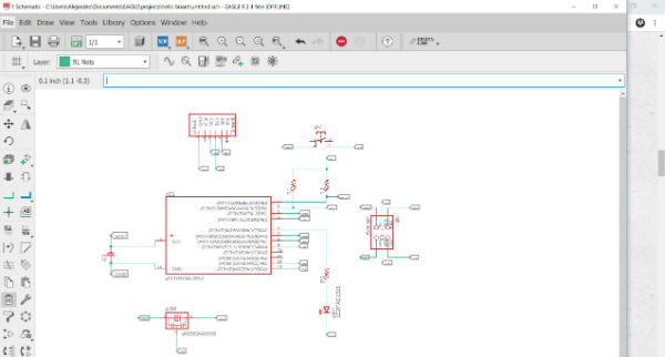
Now if I have left a much cleaner and readable circuit, without tracks that are stepped on and with each component separately.
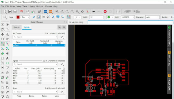
With this circuit made in schematic I move to the window of board: window / board. This window is different from the previous one and here you can see the design that will remain on the plate. To apply the design rules that we have previously added, we open tools / DRC ... / load and load the file. dru that we have in the design rules folder. With this we have added all the features that we want to give the tracks and the board.
Once loaded we have to place the different elements in the position that best fits and we also have to connect their terminals with the terminals to which they have to go connected, thus designing the tracks of the pcb. We have determined the thickness of these with the design rules file.
My plate is as follows:
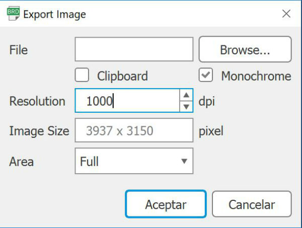
Once we have the final design, we go to the option of layers and remove the visibility of all but that of the tracks in red. When we see only the tracks, we will export this plate in .png. Let's file / export / image, select monochrome, the resolution at 1000 dpi and export.
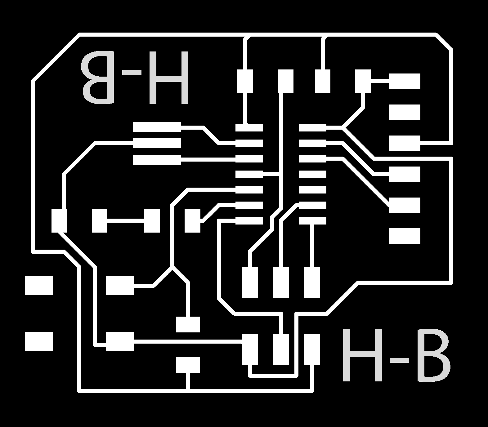
The program has a bug and when opening the image in an image editor the size has doubled. Therefore, I cut it in half and I also create a contour to cut it. My Hello-board has remained as follows:


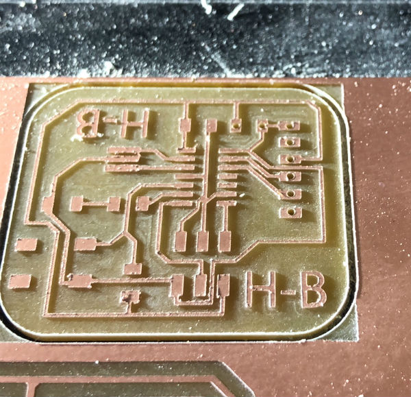
It's already Monday and I have to mill the plate to solder and test it. I follow the steps followed for the assignment of electronics production
for the milling of the plate. And I also add drills made with the 0.8 mm bur. To be able to solder the capacitor and the FTDI connector.
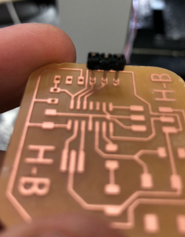
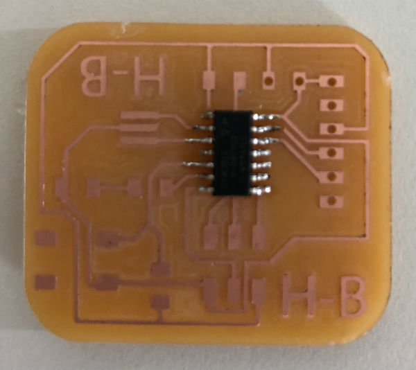
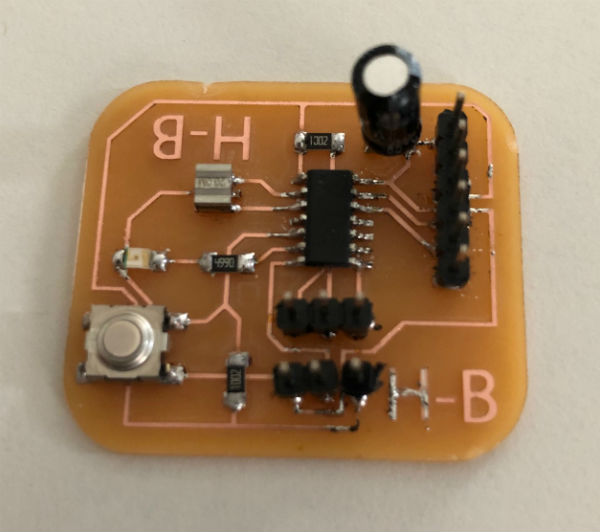
With the milled plate, I start to solder all the components and I'm checking the continuities in them. As I did not have a 1uF plate capacitor I had to place another type of capacitor with the same value.
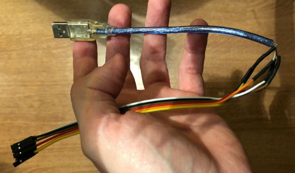
I connect my board through a homemade FTDI cable that I have made by recycling an old cable and cables with female termination, following the following scheme:

Once my board is connected to the computer, it should not look anything, but my led is turned on and pressing the button goes off, then I check again and again the circuits and the continuities inside the board observing that there is no error and reaching the conclusion that it may be that the ATTiny 44 comes from factory programmed.
For this I decide that the most sensible thing is to burn the bootloader from Arduino and upload a new program to check that it works correctly. I'm already on Tuesday and I have to schedule and check that my badge works, so I decide to leave the group assignment for next week that I can take a while.
To burn the bootloader and re-program my badge I need my Fabisp programmer produced in the electronics production week. I also need a programming program that in my case I will use Arduino v1.8.7.
I start installing the libraries for micro ATTiny, these libraries / cards I will install from a URL that is as follows:
http://drazzy.com/package_drazzy.com_index.json
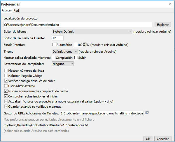
For the installation of these libraries I have to go to file / preferences and copy the URL in the window that says manager of additional card URLs.
With the URL set in this window, I open tools / board: / card manager and in this window, when the URL libraries are loaded, I look for the following: ATTinyCore by Spence Conde version 1.2.3 and install it.
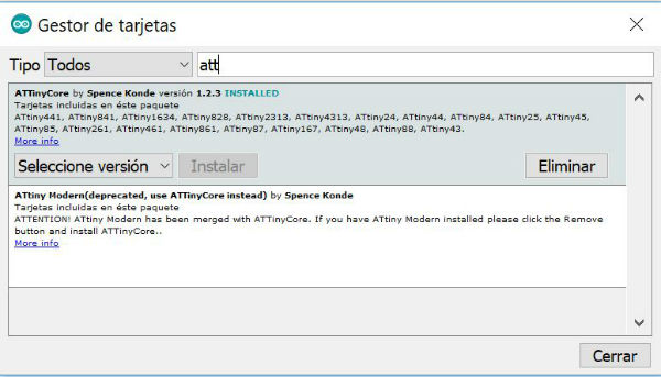
This way I already have all the ATTiny boards installed in my Arduino program.
Next, I have to select the type of micro that I am going to use and its characteristics, this I am going to do in tools, selecting the following parameters:
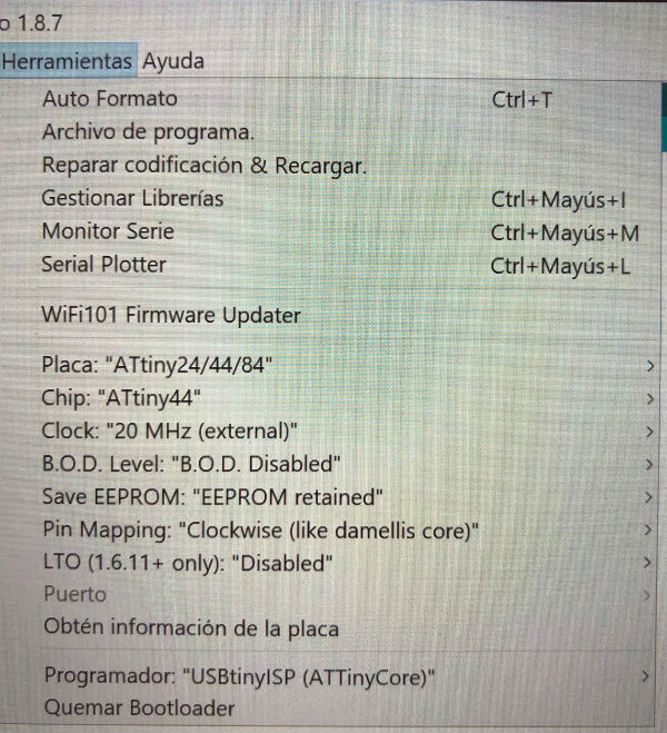
We can see how I have also selected the USBtinyISP (ATTinyCore) programmer which is the type of programmer that I will use.
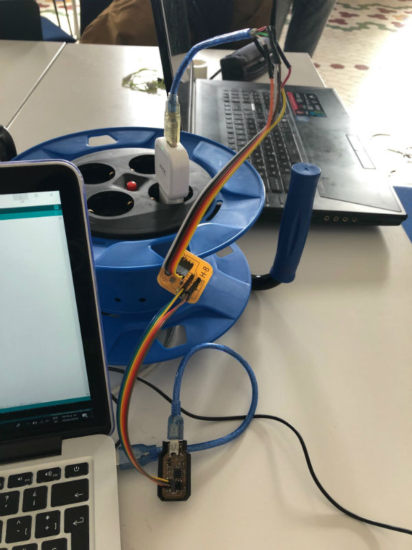
On the hardware side, I connect my programmer via USB to my computer, my programmer to the hello-board via flat cable and the hello-board via the FTDI cable to an external source.
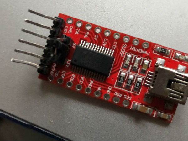
In this way the programmer should look like as in the assignment of electronics production, is being powered by the other plate and the flat cable. But mine has no power and therefore I can not have communication between my programmer and my hello-board to burn the bootloader. At first I think it is my home FTDI cable problem, so I try with a FTDI transformation plate, which I show below:
But the connection through this board does not solve my problem. So I start again to look at continuity between all the ends of the cables and through the tracks of the pcb and I notice that the VCC pin (corresponding to the flat cable) of the hello-board is not well soldered, so I turn it to solder and reconnect the assembly again. Finally my programmer is powered by the hello-board and I have communication between them.
I burn the bootloader and I no longer have any error in the Arduino programmer, it burns it correctly. Then I enter an example code from file / examples / basics / blink.
This program causes the LED to flash for a certain time.
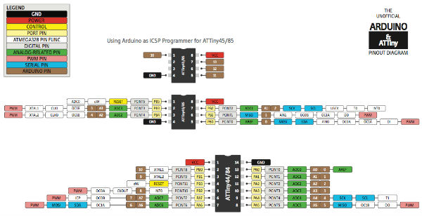
You have to know in which pin of the ATTiny we have connected the led to assign it in the Arduino program that we have created. Next I put the pinout scheme of the ATTiny 44 and the pins corresponding to arduino. In my case, my ATTiny 44 pin for Arduino is number 7.
And I also upload the code used for the programming example:
int ledPin = 7; // pinout of the attiny44
// the setup function runs once when you press reset or power the board
void setup () {
// initialize digital pin LED_BUILTIN as an output.
pinMode (ledPin, OUTPUT);
}
// the loop function runs over and over again forever
void loop () {
digitalWrite (ledPin, HIGH); // turn the LED on (HIGH is the voltage level)
delay (1000); //
digitalWrite (ledPin, LOW); // turn the LED off by making the voltage LOW
delay (1000); //
}
When uploading the program I check that my hello-board works perfectly and that the problem I had previously with the LED on and off by the button has disappeared.
Here I show you a video of the final program:
My files
PCB traces 1/64" PNG
PCB outline 1/32" PNG
Hello board .sch
Hello board .brd
Blink example program
Conclusions
I am realizing that in the electronic assignments I am delaying a lot since more complications arise than in the others. Also this week I have also uploaded the new website at last and this has made it even more hurried with the documentation this week.
Anyway I am happy as I have the new web upload, I have learned a lot about the Eagle program and every time I am solving more quickly the electronic problems that come to me.