
Week 05. Electronics production
02.13.19 Class
On February 13 Neil has explained to us the theory of the week on electronic production. We have seen theory about the components, about the manufacturing methods that we are going to use and about how the circuits are soldered.
He also explained how to use our machine and the different tools that we will use both to make the traces of the circuit and to cut the perimeter of the pcb. In this case, we will use 1/32” and 1/64” mills, the first for cutting the perimeter and the second for the milling of the traces.
Week planification
Like every week I have planned my work at the beginning to try to take an organization and be able to ensure at the end of the week with the fulfillment of the task entrusted. For this week I have organized it in the following way:
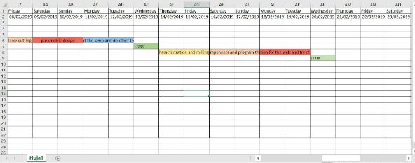
Thursday and Friday I will dedicate them to characterize my machine, the rolland SRM-20 and to mill and leave the pcb’s ready for the weekend.
Saturday and Sunday I will occupy them in soldering the components and programming the pcb.
Monday and Tuesday I will compile all the information generated, upload it to the web and try out test pcb.
Group assignment
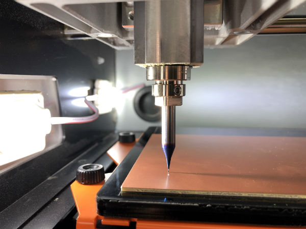
In our Fablab we use the milling machine Rolland SRM-20. The perfect tool for milling this type of small size pcb.
The pcb used for manufacturing have been FR1, cellulose-based pcb with copper coating that are not harmful to humans and do not need an extraction system in the milling machine.
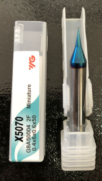
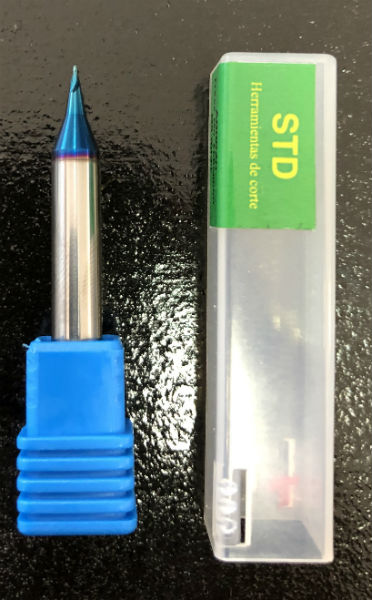
One thing that I want to monitor at this point is the life time of our tools, since our machine has a 6mm head and not 3 mm. like the rest of the machines, we have decided to buy tools with this diameter.
In addition, these tools of 6 mm. we will be used for another large CNC milling machine that we use for aluminum and steel parts.
Our local tool provider has passed us some tools with the characteristics we are looking for for materials of maximum hardness of 70 HRC, which are much harder than the materials that we are going to mill, therefore we will monitor them to see how much more the life time and see if it compensates the price they have.
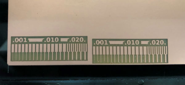
1/32" Mill (47€): 10 min. life (not broken)
1/64" Mill (42€): 212 min. life (not broken)
As I use the tools, I will update this information to keep track of traceability.
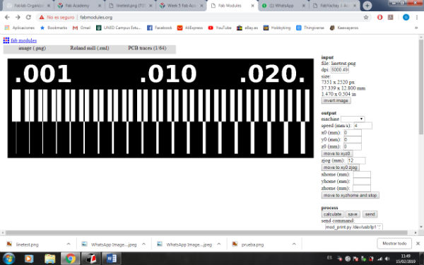
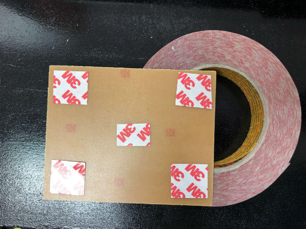
In addition, I have learned how to configure the tracks and the PCB cuts on the fabmodules page. For this we have stuck with a double-sided tape a virgin pcb in the sacrificial bed of the machine, we have made the zeros in the area where we wanted with the program of use of the machine called V-panel and we have launched the file generated in The fabmodules. To learn how to use the machine and configure the parameters I used the following information:
Electronics production with Roland SRM-20
Once I have tried the mills and I see that all the parameters of my machine work, I decide to go to mill my own pcb and to do the individual assignment.
Individual assignment
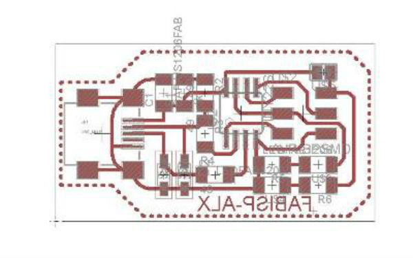
For this work I have decided to rely on the Alex pcb.
Alex assignment on electronics production
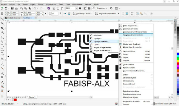
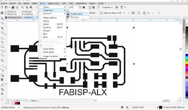
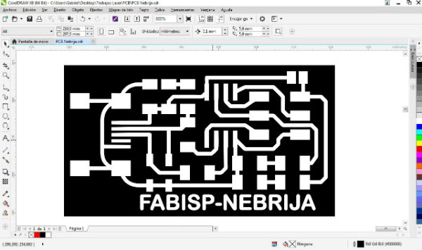
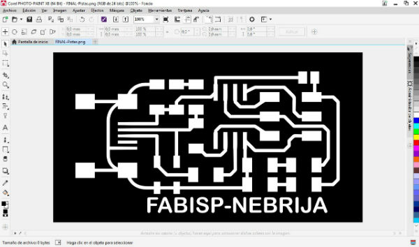
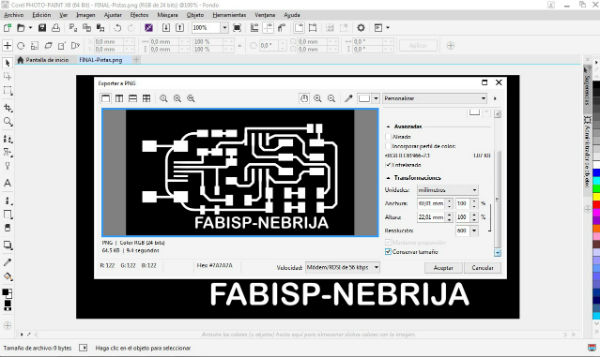
I downloaded his template in PNG. from the previous link and with corel draw program I have vectorized it so I can modify it to my liking. What I have done has been to add the name of our university and fablab and then I have generated the files to open them with corel photo and be able to save them with an increase in quality at 1000 dpi so that after the fabmodules read it correctly.
Once I have processed the image, I open it with the fabmodules and follow the instructions that Alex has put into the manufacture of his pcb since he has had several problems when entering the parameters. The most important change that must be made is the diameter of the tool: 0.3 mm. This serves to distort a bit the trajectories of the tool and thus generate all the traces of the pcb, if we do not falsify the tool there will be clues that are not created and are joined. The depth of cut Alex says that puts it at 0.2 mm. But I have tested 0.1 and there is no problem. And finally, Alex gives three offsets to the path of the tool, I want to make a complete emptying, I do what the fabmodules tells me and frame -1
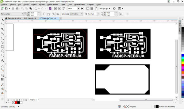
For the exterior cut I follow the same dynamics as for the tracing of the tracks but in this case I select the cutter of 0.8 that will be responsible for this action. For both actions I used both the tutorial described for the SRM-20 and the assignment performed by Alex.

Once generated both the track milling file and the cut in .rml file, I open the v-panel from which I operate the machine and send the files. I make the zeros in the point where I want to cut and cut, I select the type of file that I am going to introduce and I put the corrections 100% in:
Setup>modeling machine>RML-1 Setup>corrections>distance adjustment
Then I have to select the file that I am going to mill and I do it in the following way:
Cut>add>select file> output
And we will start to perform the action that we have selected.
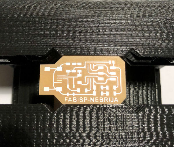
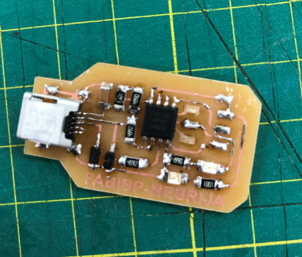
Next, I show the pcb that I have been able to make on Friday during the day, the only one that serves me, I will take it to the house at the weekend to be able to soldered it and program it.
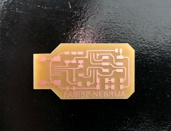
Once I have the board, I download the circuits of the Alex page, I collect all the components that I need for the assembly and I begin to soldered:
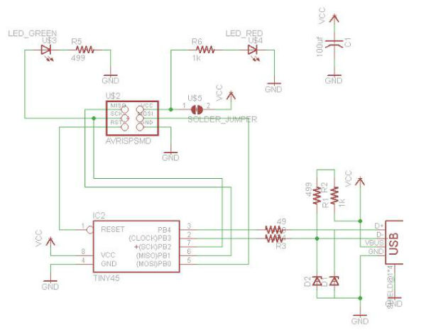
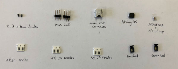
COMPONENTS LIST:
1 x ATtiny45 or ATtiny85
2 x 1 kΩ resistors
2 x 499Ω resistors
2 x 49Ω resistors
2 x 3.3v Zener diodes
1 x red LED
1 x green LED
1 x 100nF capacitor
1 x pins of 2x3 pins
1 mini USB connector
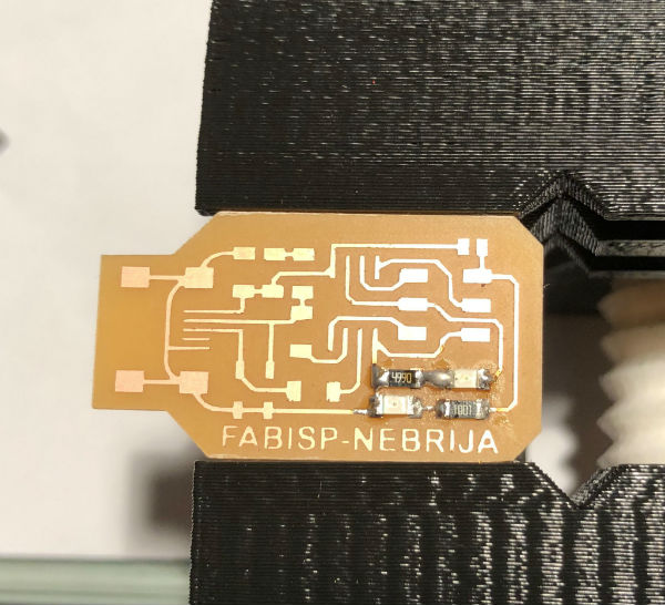
I have had many problems when soldering since the smaller tracces overheated and I have taken off the fiber cellulose support and this has meant having to make three different pcb’s to achieve the final plate. This mishap has meant a delay in my planning and as of Monday afternoon I still have not been able to program the pcb and I have to start with it as soon as possible.
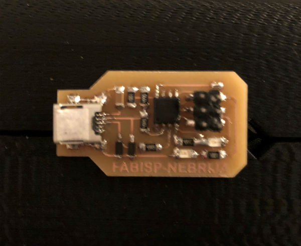
After two unsuccessful attempts and one succesful I have to start programming the plate, I’m a bit delayed with the planning prepared but I still have time for it.
I continue to follow Alex’s assignment for this task, but he also helped me with Brian’s work to complement my knowledge.
I will do the following steps to carry out my programming:
1. Software installation (in my case Windows).
1.1. I start installing the following parts, each one has a different shape.
Git(I have installed it previously)
Atmel GNU toolchain “AVR 8-bit Toolchain v3.62-Windows
(download the compressed file, unzip it and bring this folder to C: / program files)
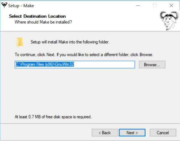
GNU Make
(we select the link and it is executed, in the window that I show next we select that we want the files in C: / program files (x86))
 Avrdude
(Download the compressed file, unzipped it and take it to the folder C: / program files)
1.2. Once we have done all these steps we must update our path, we must check that it is the PATH OF THE USER VARIABLES.
Start> advanced system settings> environment variables> user variables for Alejandro (in my case)> path> edit> new> browse> I look for the Atmel GNU toolchain folder in C: / program files and add it.
new> browse> I look for the GNU Make folder in C: / program files (x86) and add it.
new> browse> I look for the avrdude folder in C: / program files and add it.
Then I accept all the windows I had opened so that the modifications can be updated.
1.3. Installation of my programmer's drivers.
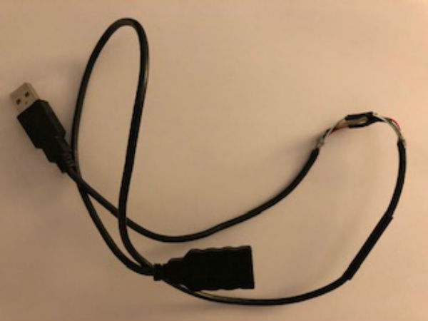
We will use this installation through a program called - Zadig and we will use it since we are working with Windows. This is where I get the first problem, since I do not have USB extension cable and the programmer that I have left since Fablab Leon is Brian and what happens is that my USB ports do not read the programmer directly because they do not get to do contact between your tracks. For this I have made a homemade cable connecting a male and a female USB to get the perfect connection. I connect the “mother” programmer and leave it connected until almost the end of the process.
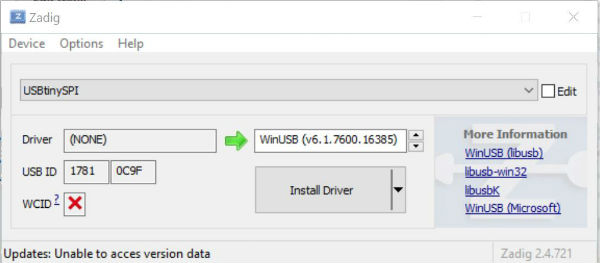
Once I have the cable connected and the computer reads it to me, I open Zadig and it does not read me, I have to open options menu and click “list ll devices”. Then I see the usbtinyisp and what I should do is install the driver libusb-win32 or libusb0 and click install driver.
Once the drivers are installed in the programmer, we move on to the next step.
1.4. Check the work done.
Open the git bash and enter the following commands to see if you have located the folders previously entered.
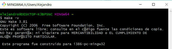
Make -v
GNU Make 3.81
Copyright (C) 2006 Free Software Foundation, Inc.
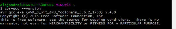
Avr-gcc
avr-gcc.exe (AVR_8_bit_GNU_Toolchain_3.6.2_1759) 5.4.0
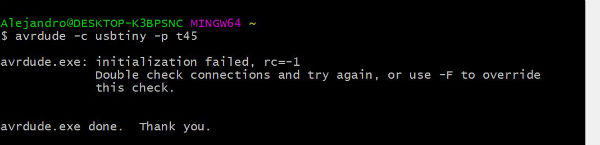
-c usbtiny -p t45
avrdude.exe: initialization failed, rc=-1
With all this checked we can move on to the next important step.
2. Get and build firmware.
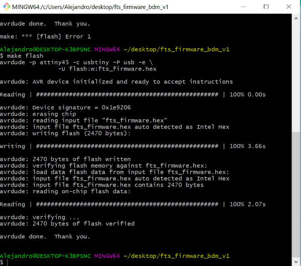
I download the - firmware and I extract the folder in a place that has located. Inside this folder I need to have a file with .hex extension for it through the git bash I access the downloaded folder fts_firmware_bdm_v1 and I make the following command: make This command has created in my folder the file with a .hex extension.
3. Program ATtiny with an ATtiny programmer.
With the programmer that we have previously connected, we are going to program our programmer, for this we join through the flat cable of 6 pins, taking care to put it in correct position so that the correct pins of the microphone are connected. In addition, we will connect our new programmer to an external power supply, be it a mobile charger or a portable battery, and in this case I have connected it to a portable battery. Once we have made this connection, we get into the git bash and perform the command: make flash This command is the one that will copy the firmware in the new programmer.
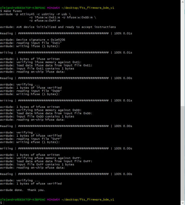
After this we perform the command: make fuses
Once this is done correctly, I have disconnected the mother programmer from the computer and from my new programmer and I have connected this to the computer separately to verify that it reads it to me without problem. Here I have started to have big problems. My computer did not read my programmer and I started to perform different tests to discard possible that could have done.
The first thing I did was to repeat the whole process again and reprogram my programmer, if in any of the steps I had made a mistake and I had not realized the error, I have also been teaching it to my colleagues and instructors and they have not I saw no fault in the process.
I have tried other computers with different connectors and different types of operating systems and I have not been successful in my search.
I have reinstalled the drivers of the usb just in case they had disconnected and could have lost the connection in my ports, but neither has it been the error.
Then I thought that the cable was not of sufficient quality and this has influenced me in the bad connection between programmer and computer, so I have tried three cables but this has not been the problem either.
Just before I found the error I tested the continuities on my entire board and on the miniusb connector that I used in case the fault had it here.
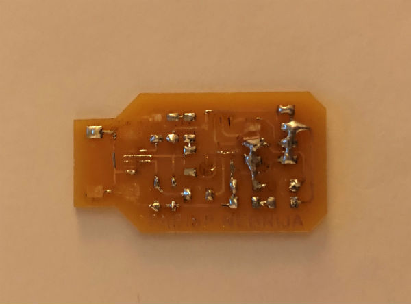
And finally I found the error, the Zener have the mark with a line on the negative side and this part had joined the gnd, forgetting that the Zener diodes are connected with inverted polarity. I changed the two diodes and checked the reading with the computer. He has read it perfectly and I have disconnected it from the computer.
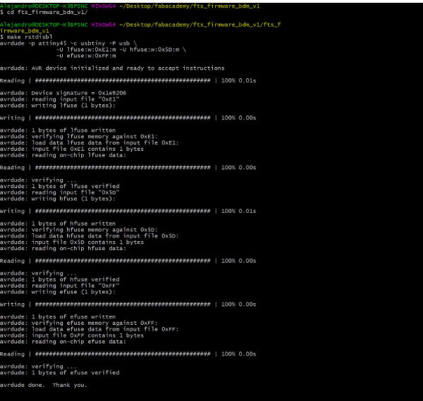
I have reconnected my new programmer to a power supply, the programmer “mother” to the computer and between them using the flat cable, I made the command: make rstdisbl and I have disconnected everything from the computer.
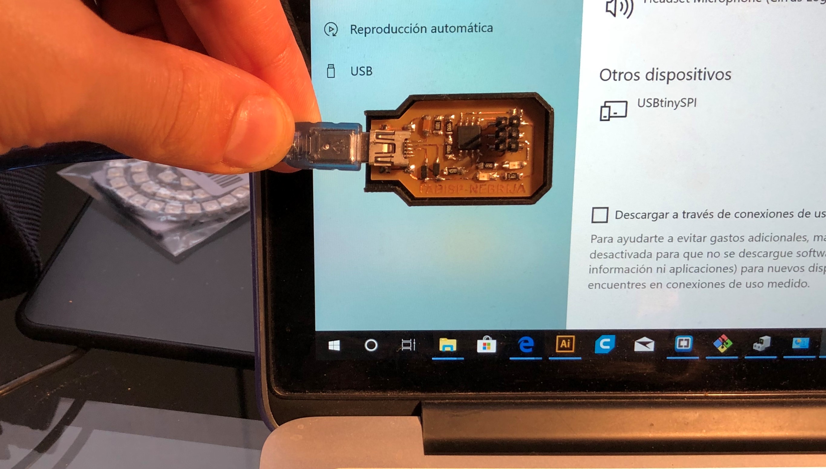
In this last photo it is observed how when connecting my FabISP my computer detects it as a USBtinySPI programmer. so I'm very happy, the mission has been successfully completed
My files
PCB traces 1/64"
PCB outline 1/32"
PCB traces 1/64" PNG
PCB outline 1/32" PNG
Conclusions
Another week lasts in the office, this assignment has been very hard to carry although at first I thought it would be more bearable. I have trusted my knowledge and I thought I could do it more quickly, but I had to work until the last minute to achieve it. I want to give a general advice and that is that in this assignment, as our instructor Nuria proposed, we should start working on it from the beginning of the course and in this way we should take the practice to work with the milling machine, to the electronic components and the welds of these on the pcb’s.