3D Scanning and Printing
This week's individual assignment was to design and 3D print an object (small, few cm3, limited by printer time) that could not be made subtractively. Moreover we had to 3D scan an object (and optionally print it). For the group assignment the task was to test the design rules for the printer(s).
3D Printing
3D printing or additive manufacturing is a process of making three dimensional solid objects from a digital STL file. It is the opposite of subtractive manufacturing which is cutting out. There are no special tools required. The printed parts are manufactured directly onto the built platform layer-by-layer. These days you can make nearly everything with a 3D printer and you also can use various type of materials. Moreover the time it takes to make a 3D print depends on the size of the model and the settings that you use for printing. Once you have created your 3D model, it needs to be exported as an STL, OBJ, DAE or AMF file. Then it needs to be imported into a slicing software, which will generate the G-Code for the 3D printer.
Group Assignment
You can find the documentaion of this week's group assignment here.
3D Design
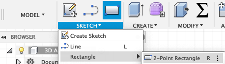
The goal was to create a model that could not be made subtractively. To create my design's I used Autodesk Fusion 360. The first thing that I thought of was to create several cubes into each other. So I started sketching a cube by going to sketch --> rectangle.
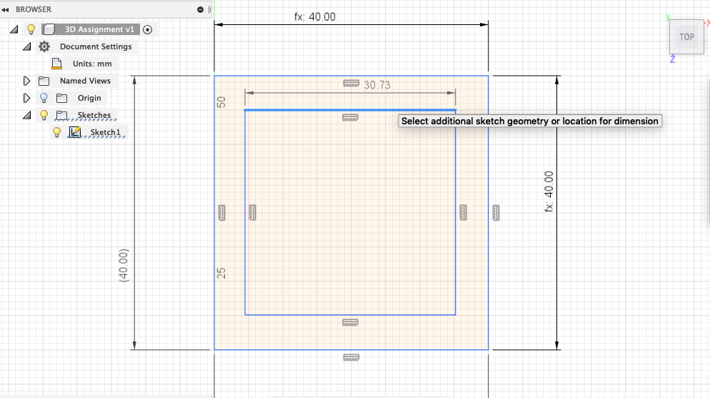
Since the idea was to only extrude the lines of the cube, I drew another rectangle inside the cube. Moreover I made a parameteric design, so that I would have the possibility to change the size of the cube.
Next I extruded the external cube.
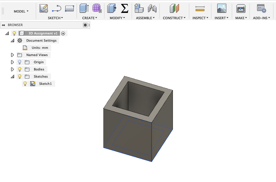
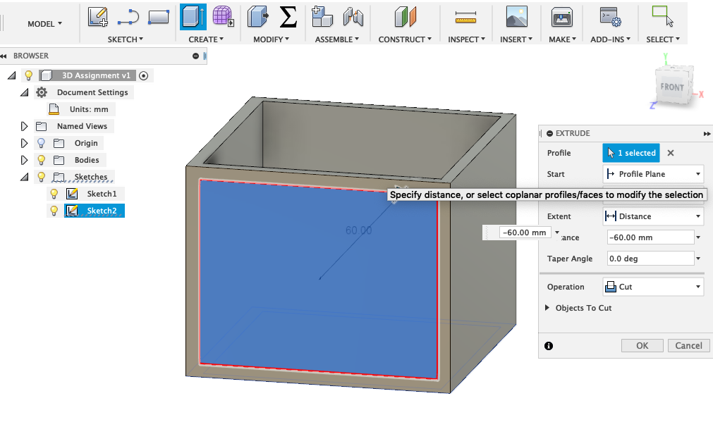
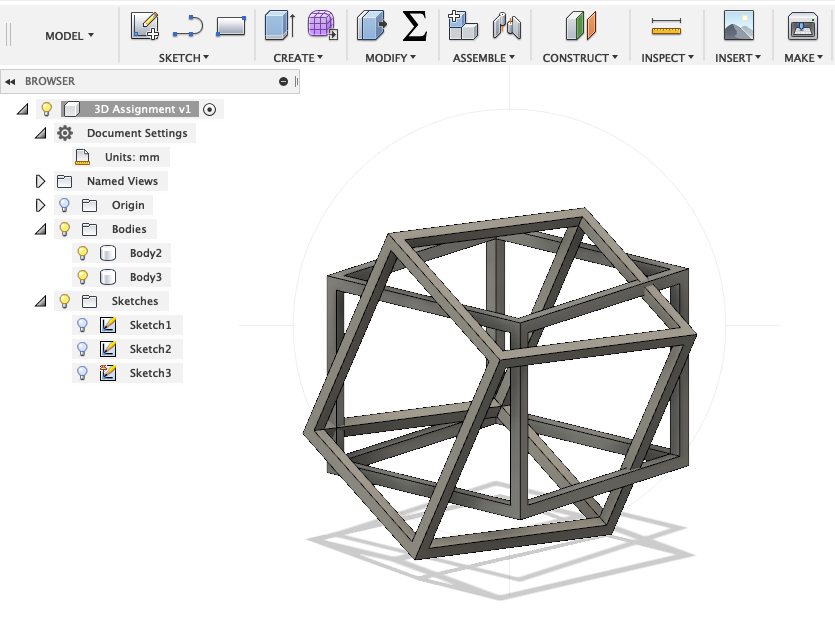
Now I had to remove the inside of each surface, to expose only the border of the cube. To do that I had to create a new sketch on the surface I wanted to modify and then extrude this part.
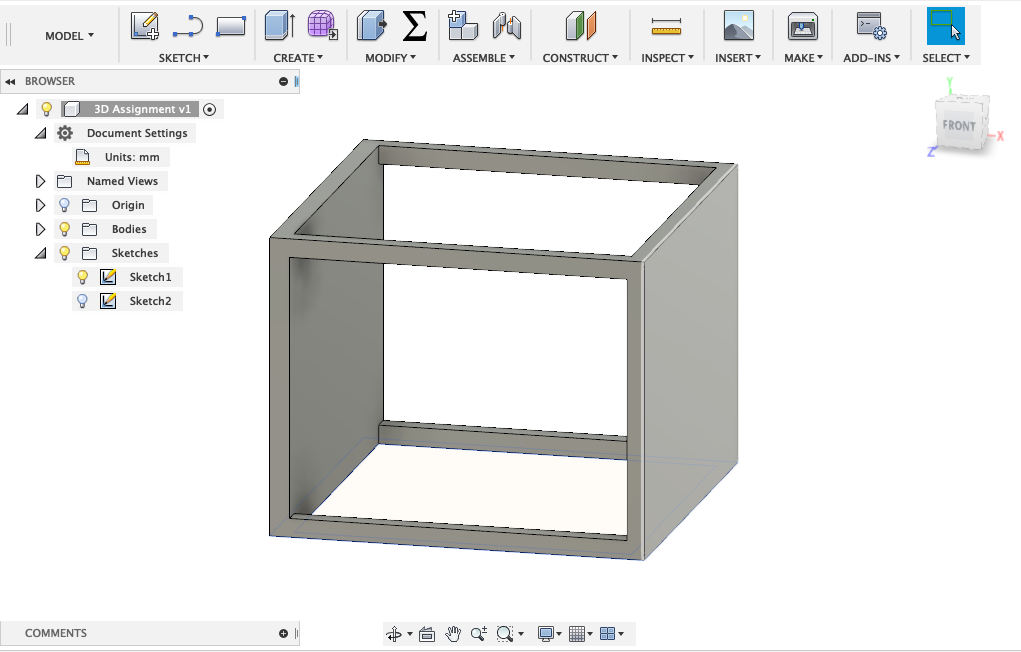
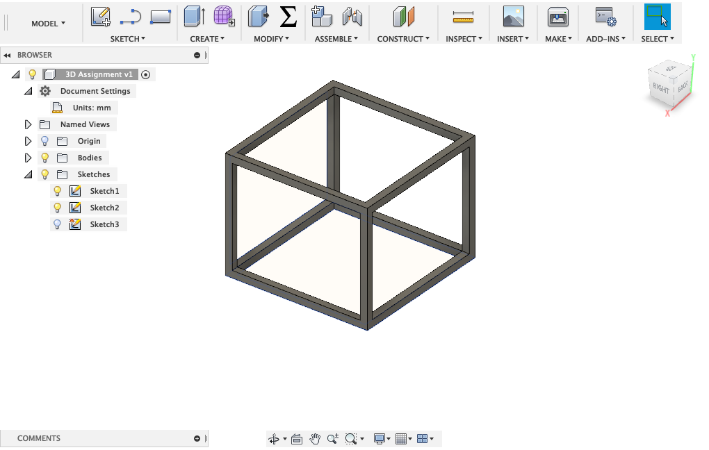
Below you can see the final design of the cube.
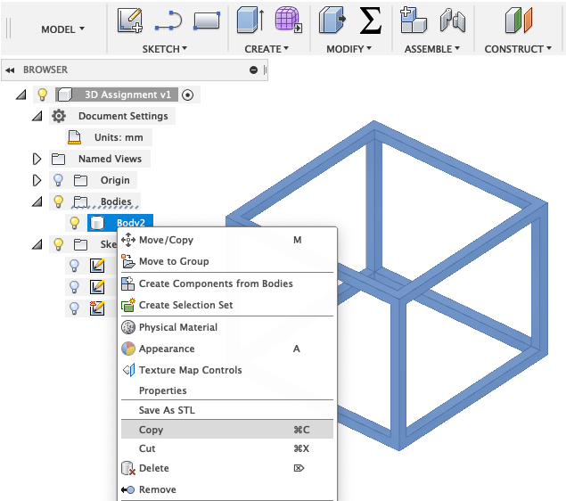
To replicate the design I just had to copy the model and paste the copy.
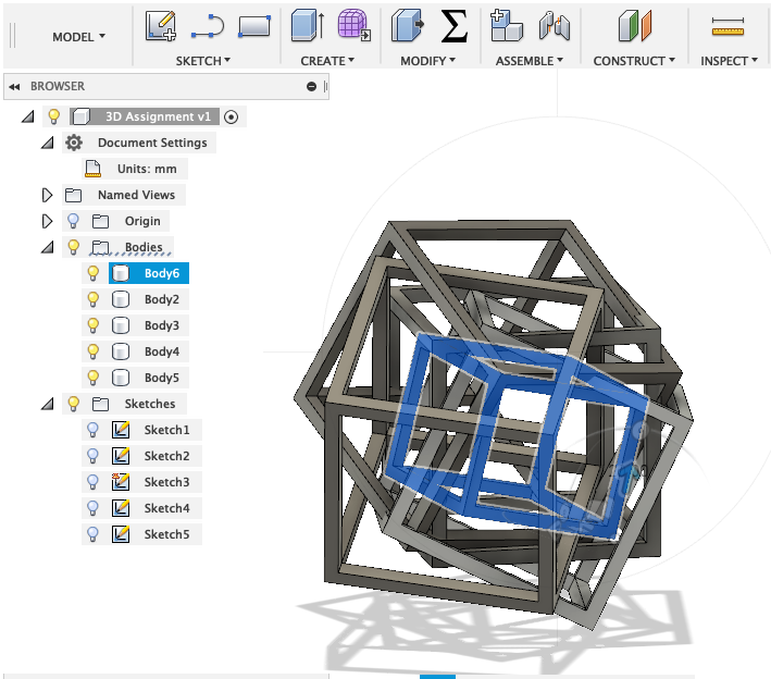
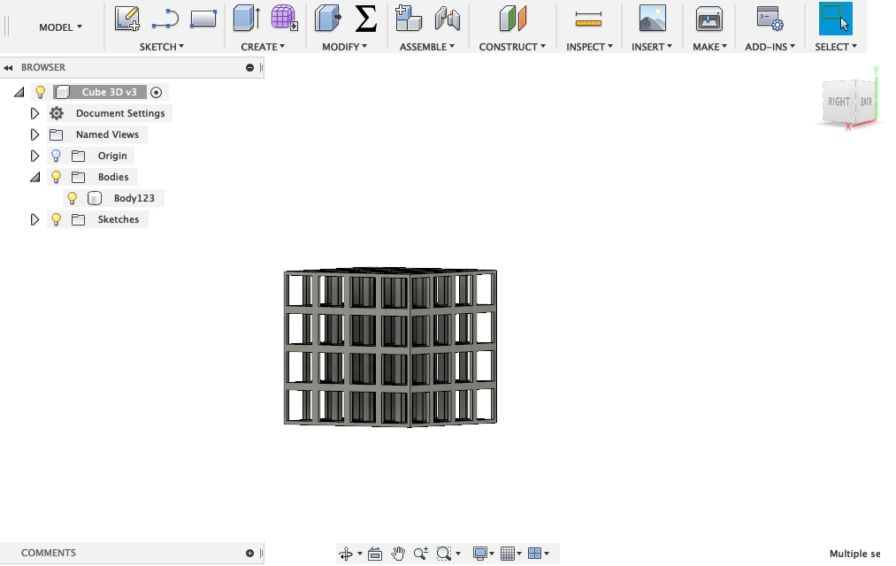
I tried to create a complex cube model, in which there are lot of cubes inside each other holding and sustaining each other.
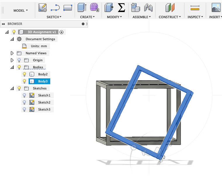
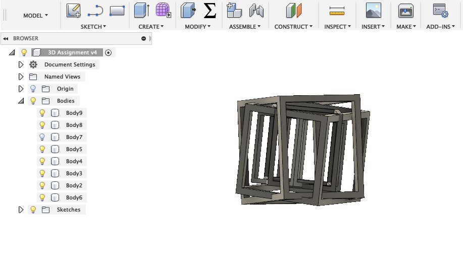
I also created a new smaller cube. Underneath you can see the final model.
Since the print of the first model didn't work out the way I wished it would have, I changed the position of the cubes. Moreover I also wanted to increase the thickness of the outline.
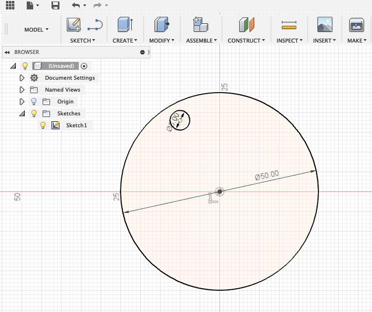
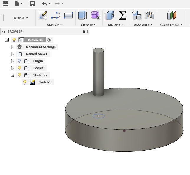
The next design I created was a cage with a sphere in it. The idea was to create a little toy, since you would be able to move the ball around. I started drawing two circles one for the bottom of the cage and the smaller one for the pillars.
Next I extruded both.
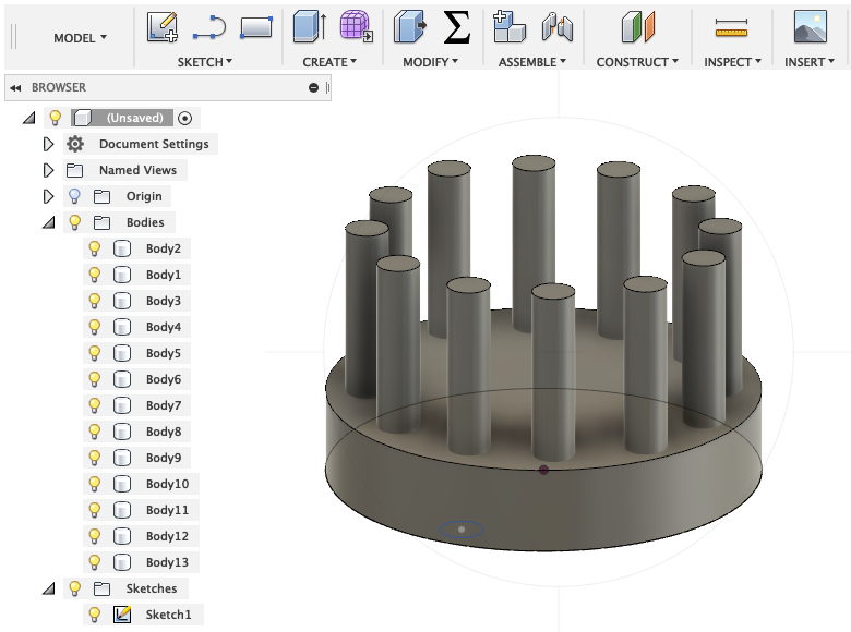
And created more pillars around the entire border of the base.
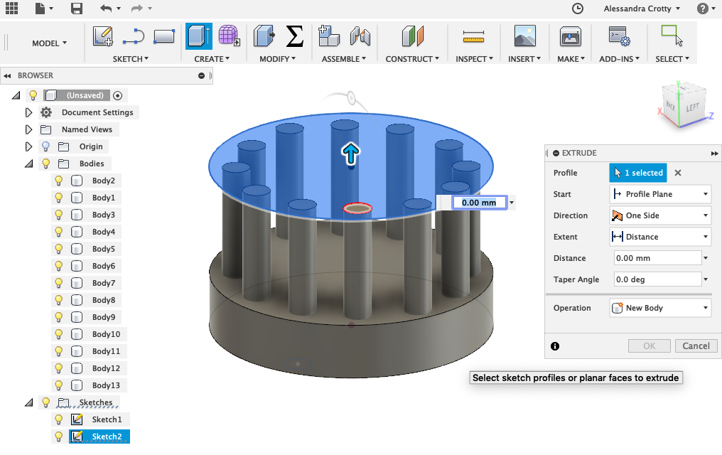
Then I drew a new sketch on one of the pillars to create the top of the cage.
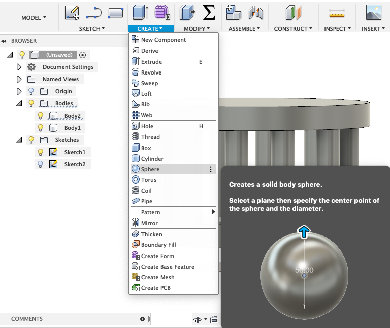
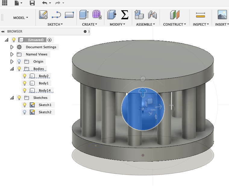
To make the sphere I went to create --> sphere. As soon as the sphere was generated I moved it into the cage.
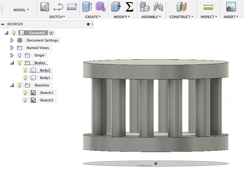
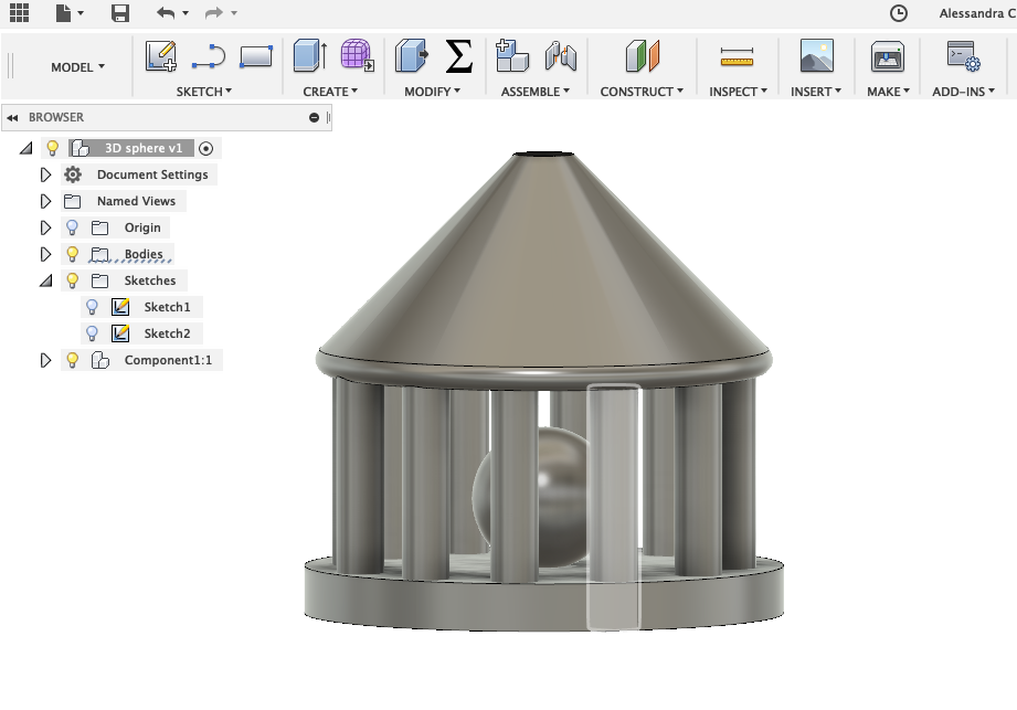
Because it was not possible to print the top of the cage without support in the inside, I had to create a shape that would be able to build the layers on each other. Underneath you can see the finished design.
At last I designed a large cube composed of several cubes using the same technique as I did in the first design.
These designs can not be made subtractively, because a CNC machine is not able to create an object that has another object inside the object. The technique of CNC machine is drilling or cutting, so it removes material while the 3D printer adds material.
Working with Cura
Ultimaker Cura is an open source 3D printer slicing application. It takes a 3D model and slices it into layers to create the G-Code, which is the code that a 3D printer understands. Cura recognizes STL, OBJ, DAE and AMF file.
On first loading Cura, you’ll be asked to select a printer. Once you have setup the right printer, you can import a model into the software. To import a model, you can either click on the folder icon on the left or select File --> Open File from the top menu.
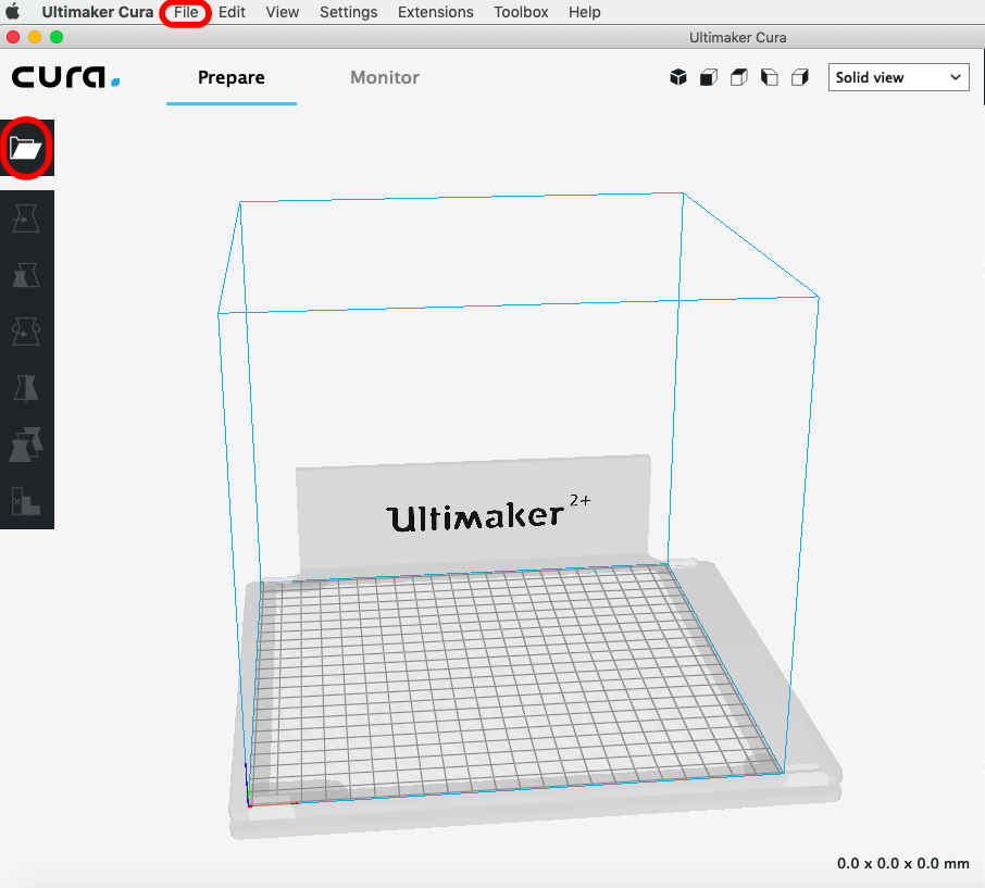
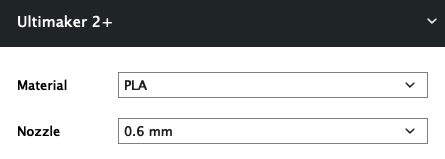
As soon as the model appears on the build area you might have to move it or scale it, in case it's to big. To be able to move the object, you have to select it first. Then you need to set the basic settings. Every printer has a different setup, print area, build plate and nozzle size, Cura needs to know these hardware details. For the 3D design's I used the Ultimaker 2+ with a 0.6mm and with a 0.4mm nozzle. Also always select the right material, since every material has a different heating point.
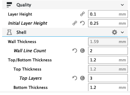
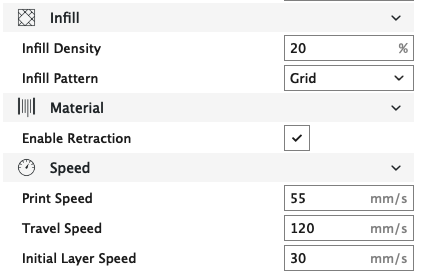
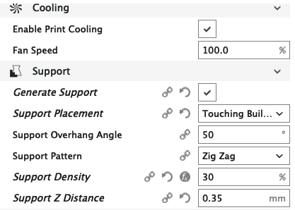
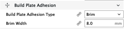
In Cura, you will find all the settings on the side panel. There are many preferences to play with. For my print's I used the following setting categories:
If you would like to know more about the different kinds of settings you can always check the Ultimaker Website, it has a really nice documentation.
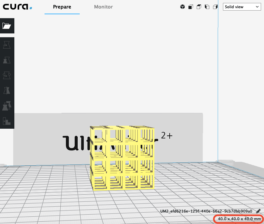
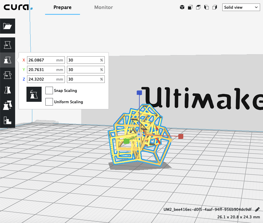
In Cura, there are different ways to view the model (Solid, X-Ray, Layers). Each is useful for different reasons. The default view is the solid view. Everytime you import a new object into the software, you will see it through the default view. It basically shows you the size and shape in comparison to the print platform. Moreover in the right corner you can see the size of your object in millimeters.
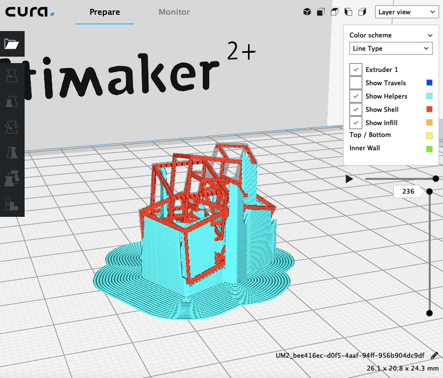
I prefer to use the layers view. You can view it as soon as you slice the model. To do this you have to click on the prepare button.

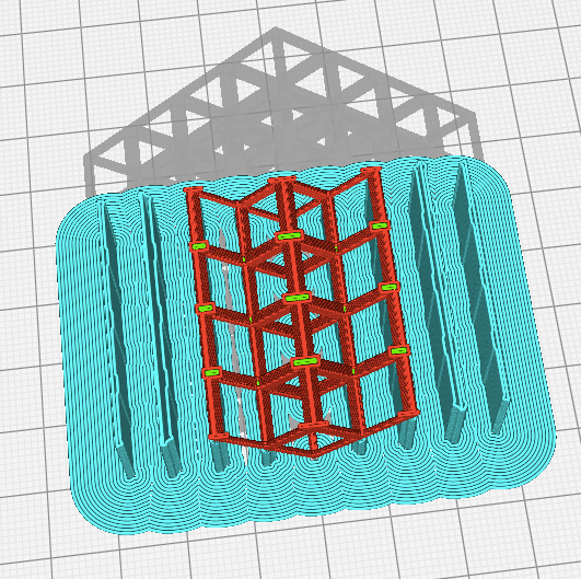
This view shows every layer in sequence. It's very usefull to check if your settings are right and to check if there are any problems with the model itself. If you use support you can change the color scheme into Line Type and you will see where the support starts and ends.
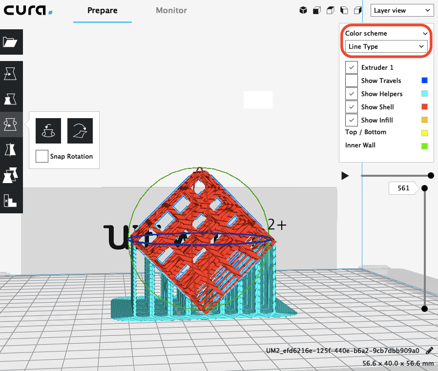
To go through every layer you can use the slider on the right.
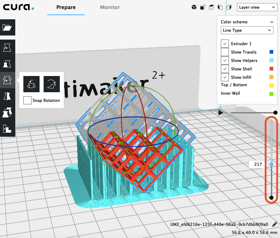
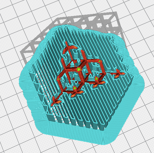
I choose to print all three designs. The first object I tried to print was the complex cube model. To achive a better print result I decided to use a 0.4 nozzle, since the lines of the model are very thin. Moreover I scaled it up to 30%, because I wanted to be sure that the print would work. So I thought it would be good to print a prototype first.
I had to add support, because there were parts that didn't have a surface to build on. As the object is very complex it was difficult to find the proper solution. I decided to set the placement of the support to touching build plate, in this way it would be easier to remove the support.
The final result of the print didn't look nice and the support was really hard to remove, eventhough it was less cause I didn't put it everywhere. The lines of the cube were very thin. They broke while removing the support.
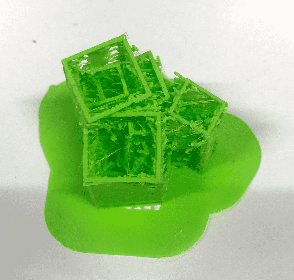
Maybe if I would increase the thickness of the lines of the cube and use a different position for the figure the print might have a better outcome. Or I could modify the file and put the cubes closer together to decrease the gabs and maybe create a surface where they could build on each other, so that I don't have to use a lot of support. Furthermore I would increase the speed to get rid of the oozing.
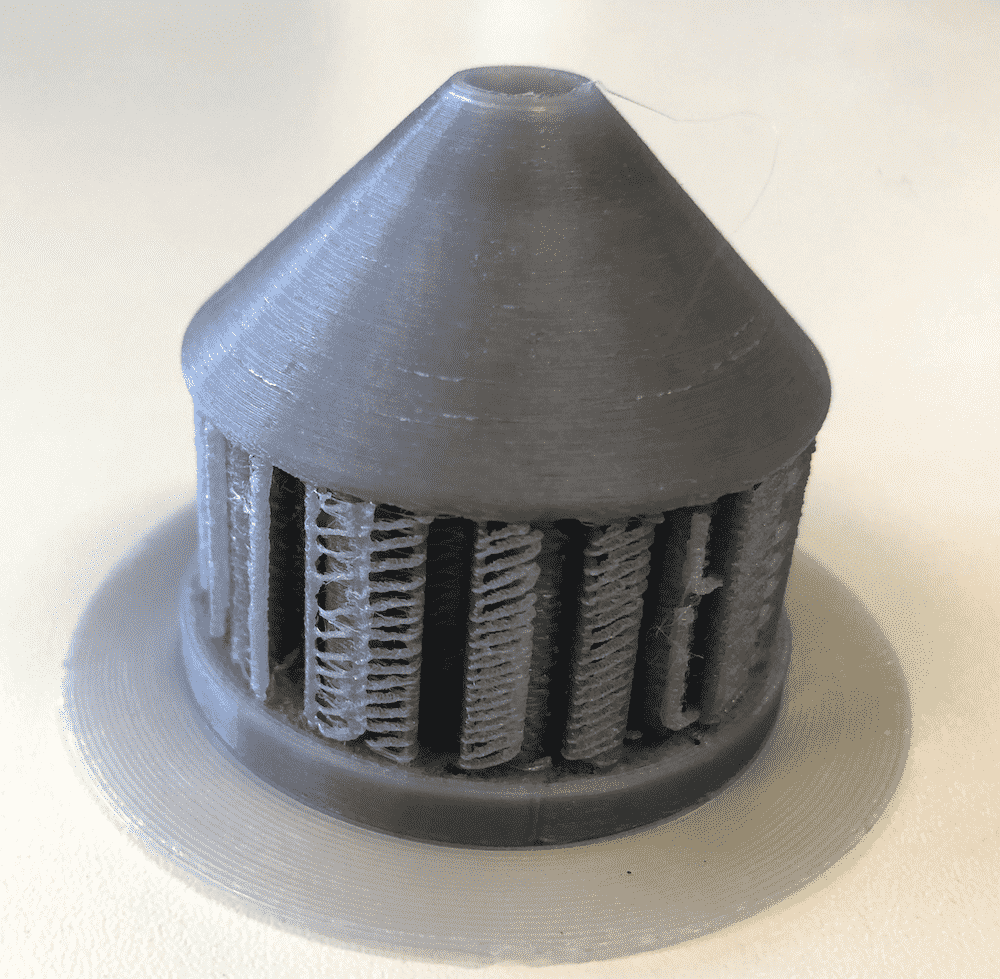
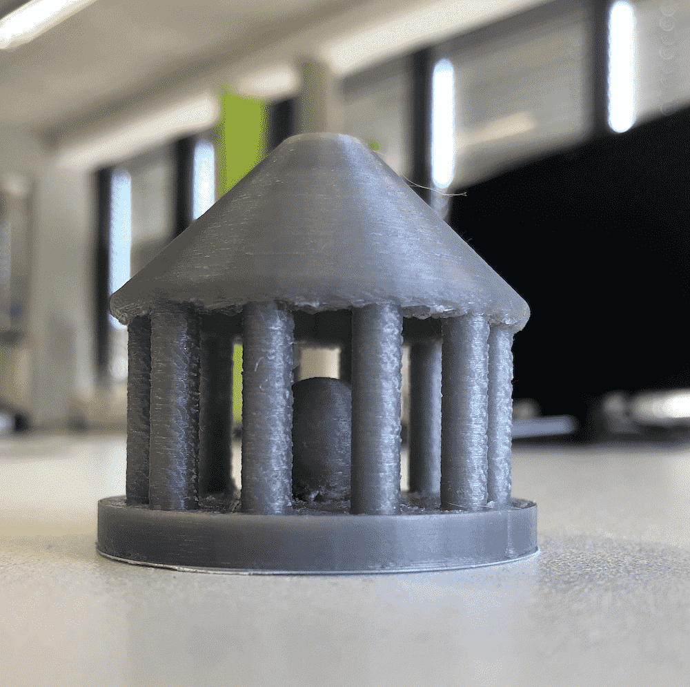
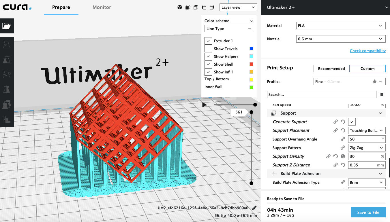
The next object I printed was the cage with the rolling sphere in it. For this print I used a 0.6mm nozzle. Since I decided to modify the top, I only needed support between the gabs of the columns. The print took around 4 hours with a 20% infill density and 0.1mm layer height.
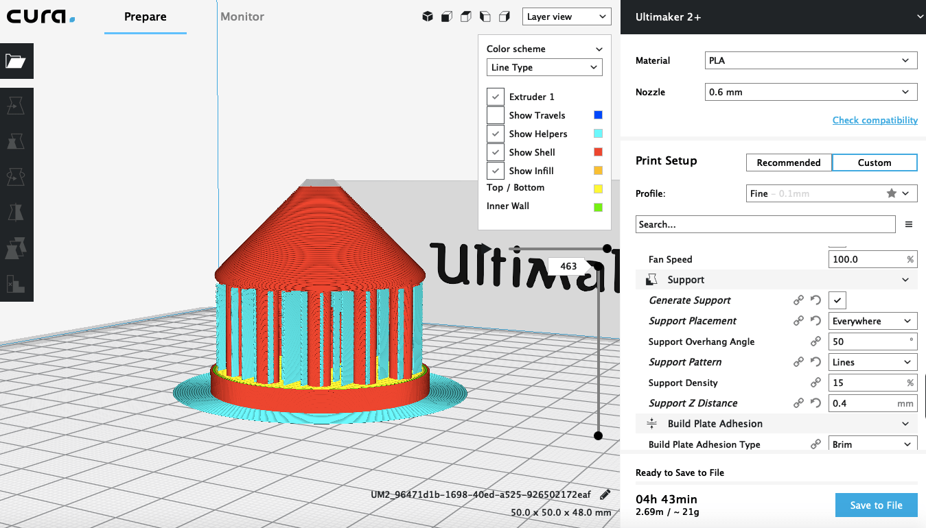
As you can see underneath there is no support inside the cage to hold the roof. The roof doesn't need any support, because of the shape I designed it allows to build on itself.
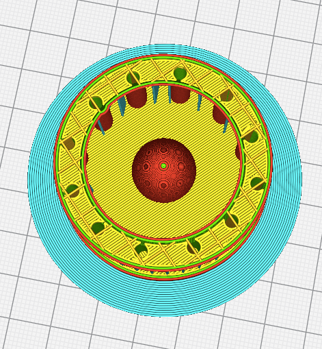
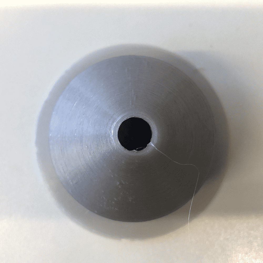
The result of the print was really nice, because I could remove the support easily. There was also a little bit of support under the sphere, but I was also able to remove that.
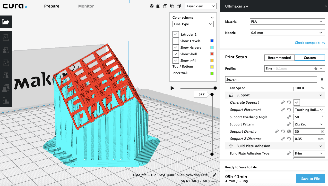
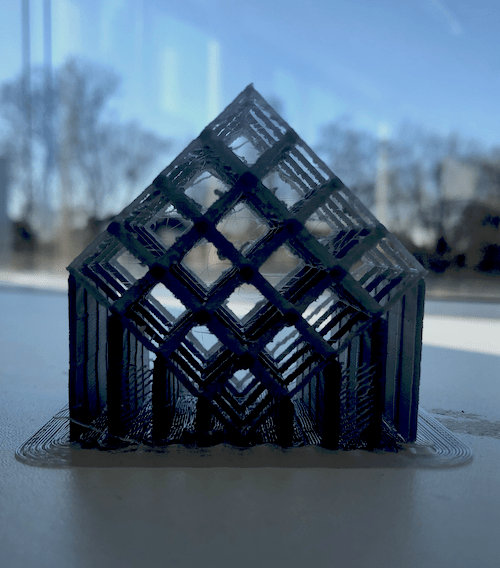
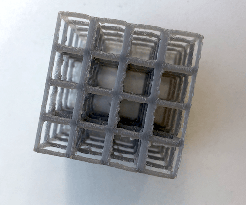
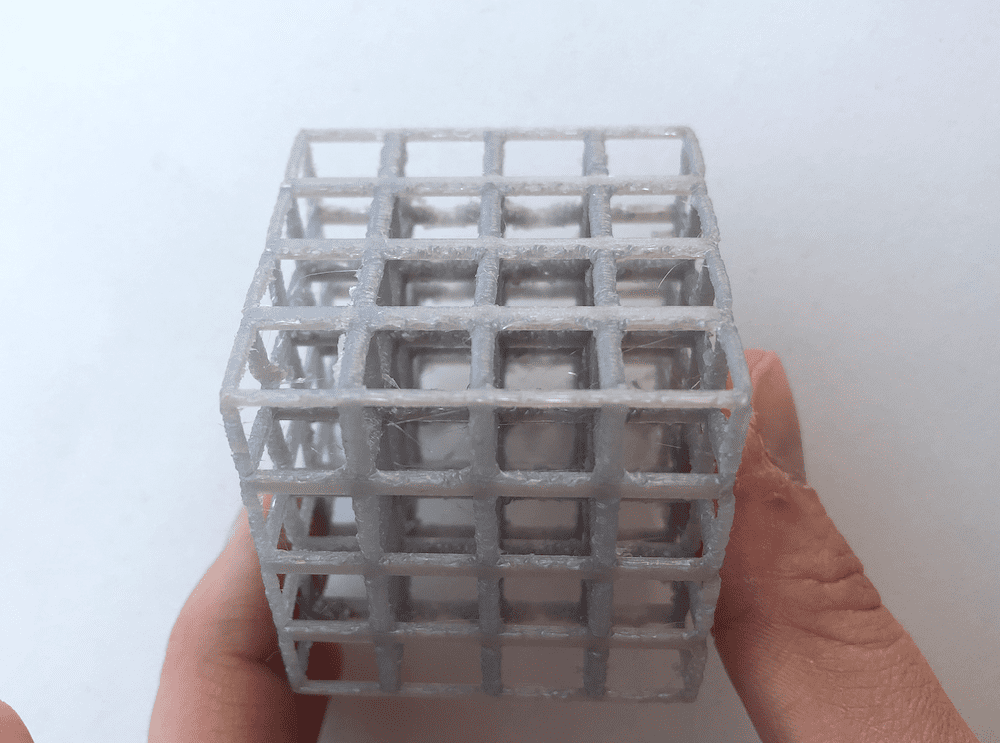
The last object I printed was the large cube created by multiple smaller cubes. For this print I also used a 0.6mm nozzle. It was a bit tricky to find the right position fot the print, since the cube contains many holes. I first tried to turn it 45 degrees to the side, so that it would lay on one of the outside lines of the cube. Moreover I used the touching build plate as support placement, otherwise the support would be inside the cube which would be very hard to remove.
Then I tried to place the cube on one edge, because I wanted to see if in this way it would have a better support. But the support was either to much or way to less. I tried to change the overhang angle, but that didn't change the fact that it had to much support in the inside and this would be very nasty to remove.
So at the end I decided to go with the first option. The end result was pretty amazing. I actually was very skeptical about this print job.
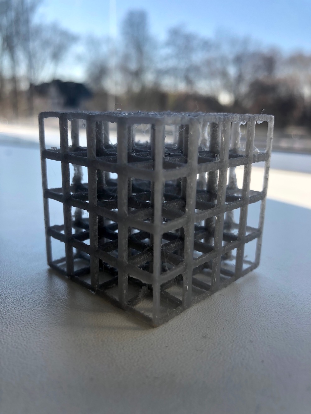
As you can see below the lines without support don't look that smooth as the ones with. The parts that stick out are called oozing or stringing. To prevent this you have to balance the retraction length on move and the travel speed. Then probably you will get a better outcome. You could also try to increase the thickness of the cube lines, to make the model more stable. I also recommend you to print with a 0.4mm nozzle or smaller to get more precise print.
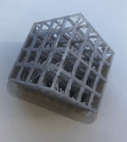
This is how the model looks after cleaning it.
If you want to learn more about how to use support correctly check the documentaion on the Ultimaker Website.
Using the Ultimaker
With an Ultimaker you can print a lot of different things, but not everything is possible, as you have seen in my prints. The Ultimaker uses the 3D printing technique FFF (Fused Filament Fabrication), with which layers of melted plastic are placed on top of each other. Therefore complex structures or “overhanging” parts are hard to print. You can use PLA and ABS as materials for 3D printing. Furthermore you can also always try other materials.
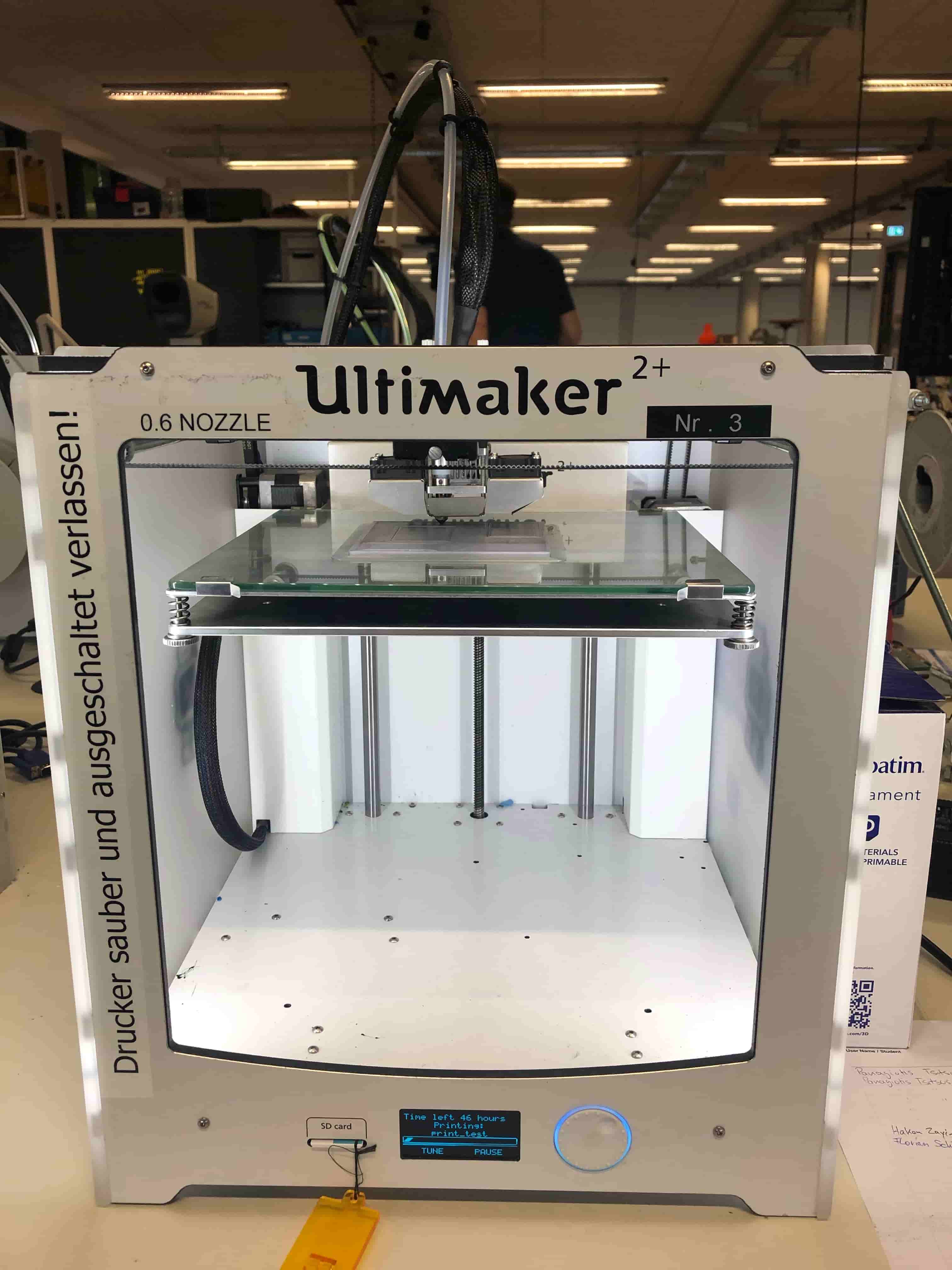
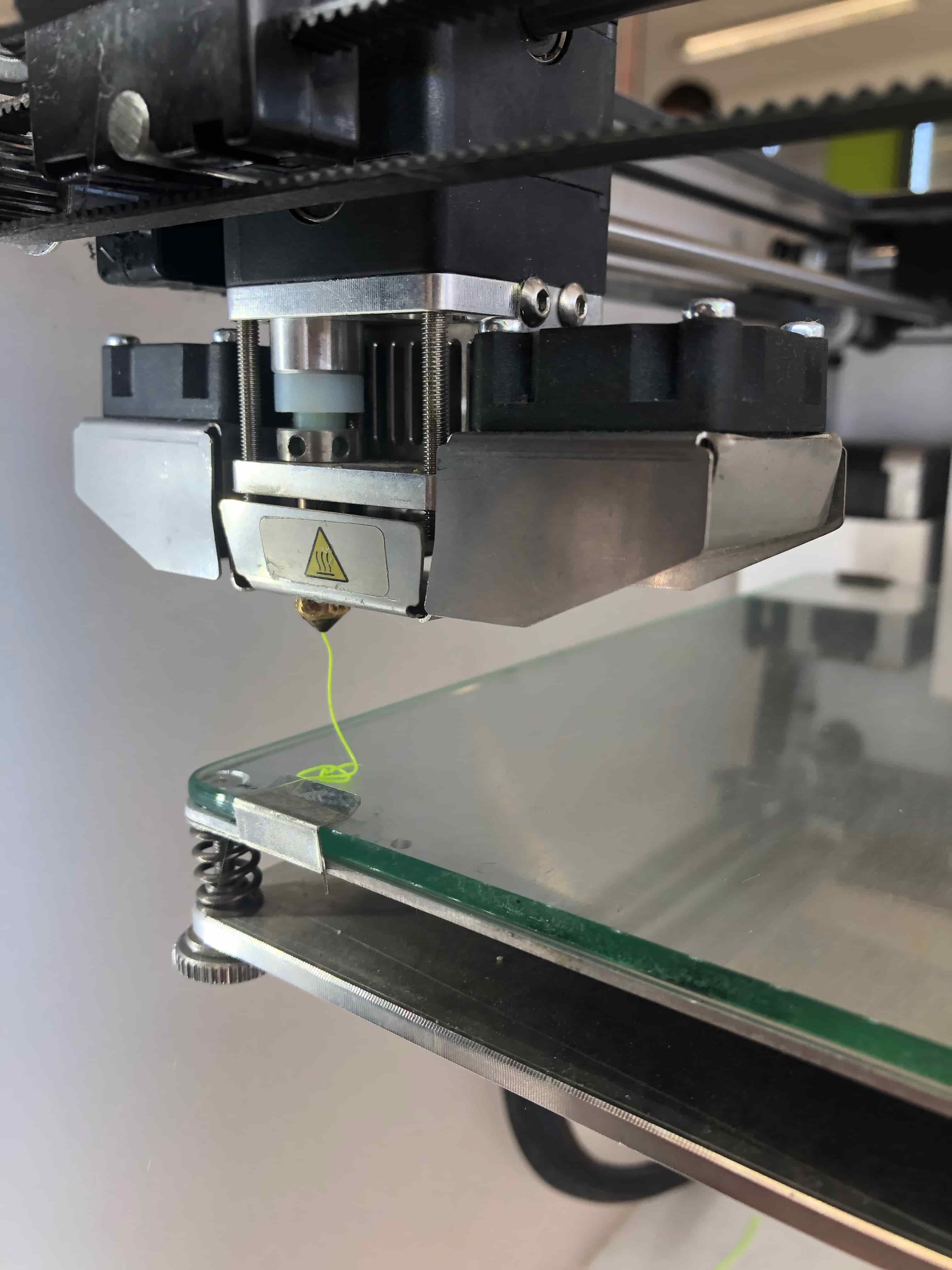
Before you start your print make sure that the surface of the printer is clean. In addition always check if the filament inside the printer is the same you set as preference, otherwise you will have to change it. Now you can start your print by inserting the sd card into the printer and then select the file. The nozzle needs to heat up in order to print, since every material has his one melting point. Before it starts printing it will extrude some filament, if nothing is coming out the nozzle might be clogged.
Moreover you always have to check that the first layers are well printed, otherwise you have to abort the print.
3D Scanning
3D scanning is a technique that captures the shape of an object or person using a scanner. I captured the exact size and shape of an object. 3D scans are compatible with Computer Aided Design (CAD) software. You can these scans in Fusion or every other Computer Aided Design software or you can print them with a 3D printer.
Using Sense 3D Scanner
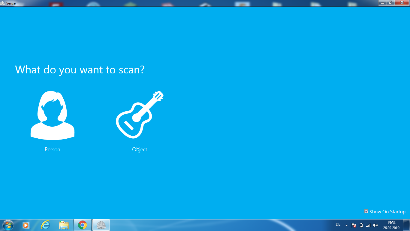
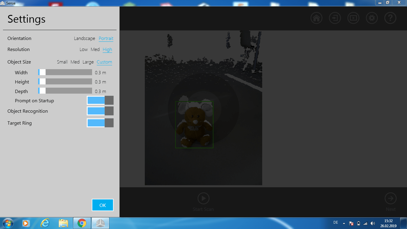
To complete the Assignment I used the Sence 3D Scanner. For this task I had to use another laptop, since the software that comes with the scanner isn't compatible with mac. The Sence software was really easy to use. Before you start scanning you have to choose what you want to scan. You can choose between a person or an object. Since I wanted to scan a stuffed animal I select object.
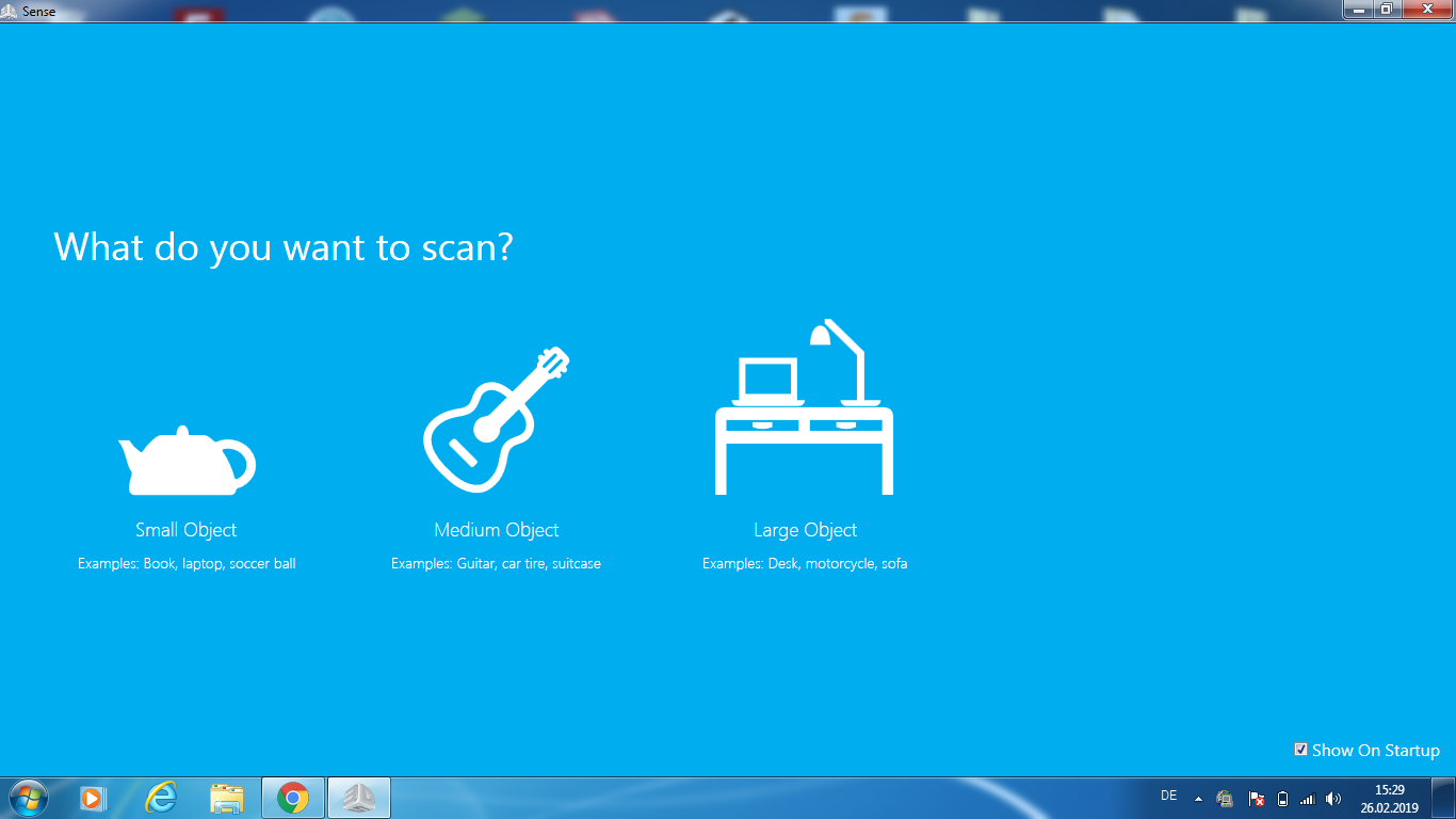
Next the software asks you to select the proper size of the object.
Then the scanning surface appears and you can start the scan, as soon as the scanner recognizes the object. Whenever you see a green rectangle around the object, the scanner recognized it.
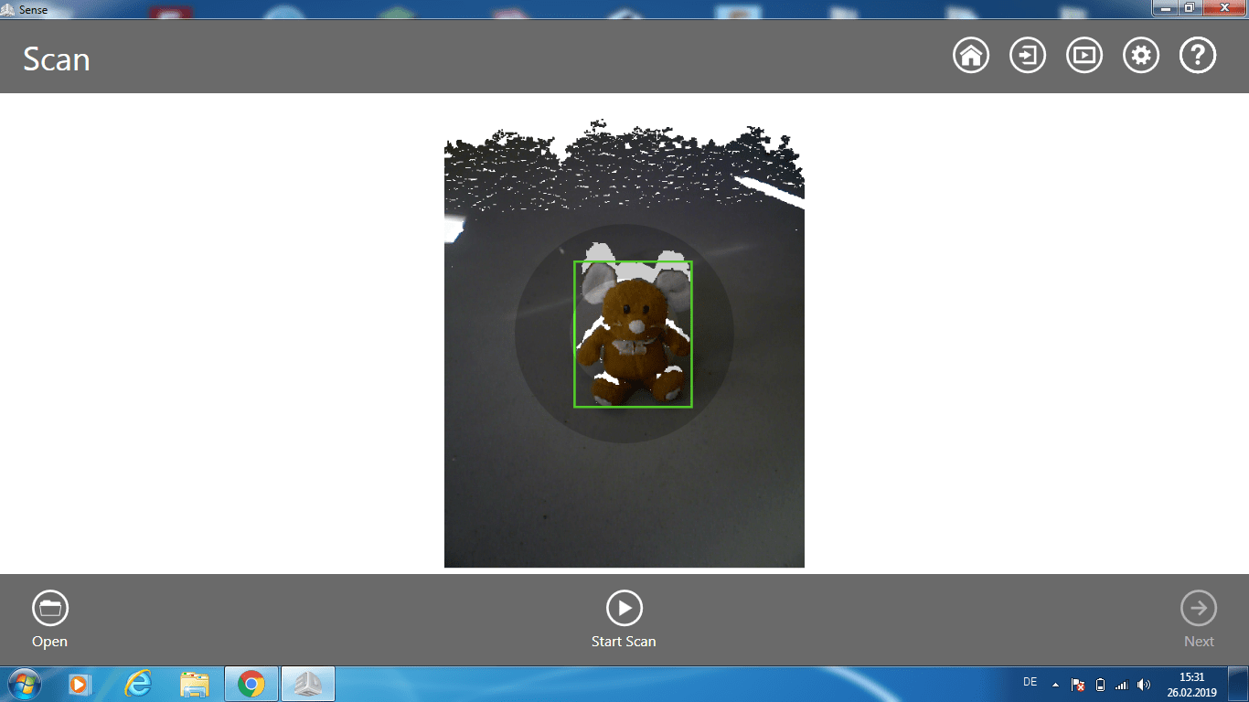
Furthermore I changed the settings into costum to transfer a more precise size of the object. Now click on start scan.
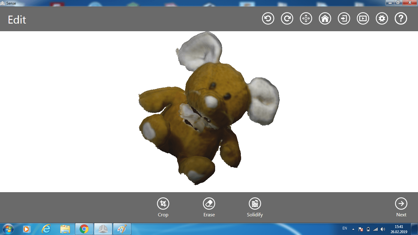
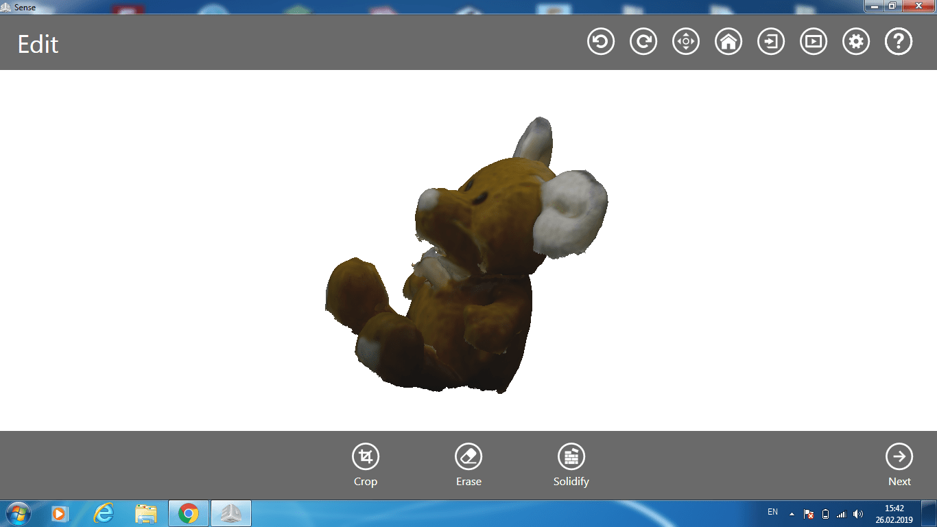
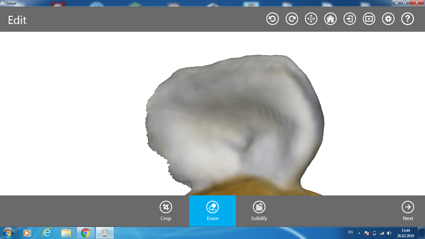
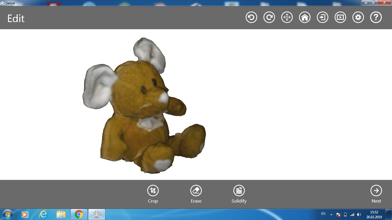
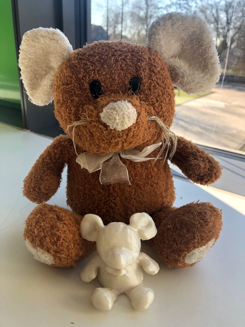
I had to scan the object three times, because it was difficult to get a smooth shape without missing parts. Especially the ribbon around the neck of the teddy was hard to capture. Below you can see the final result.
After the scan I used the rubber to erase some nasty details.
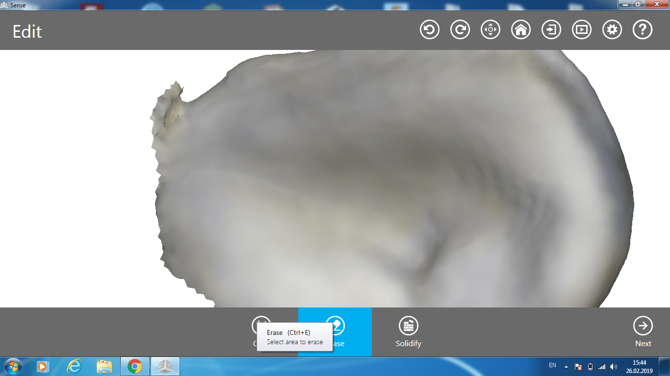
Then I clicked on the solidify button at the bottom. This feature repairs all the holes and makes the object solid.
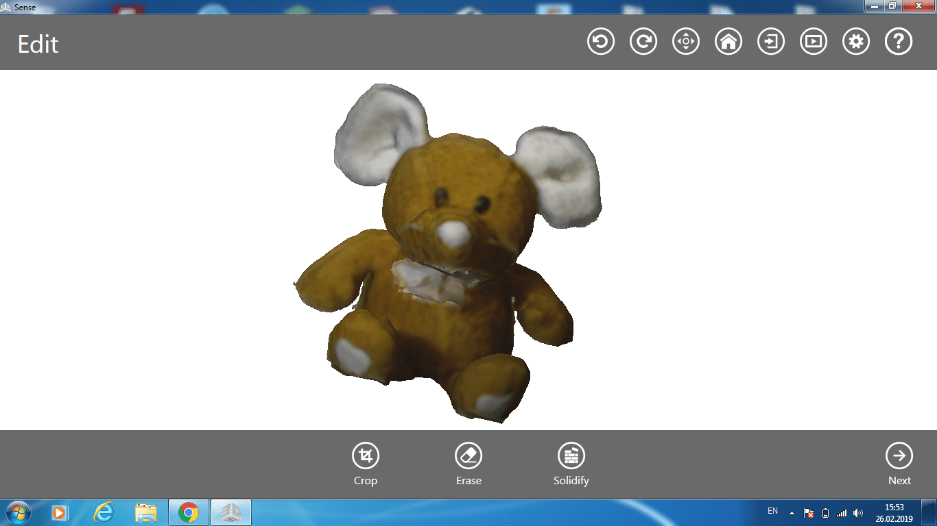
To have a nicer outcome I smoothed all the edges. Finally I exported the file as OBJ and imported it into Cura. Here I had to scale the object, since it's as big as my stuffed animal.
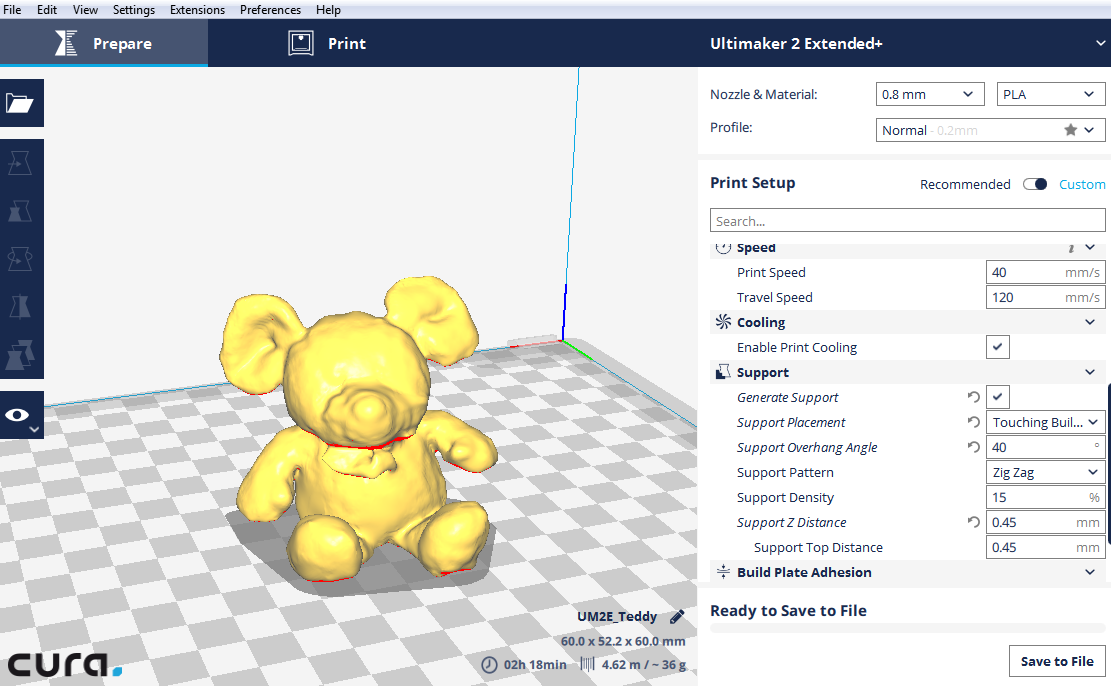
I choose to use a 20% infill with a grid pattern.
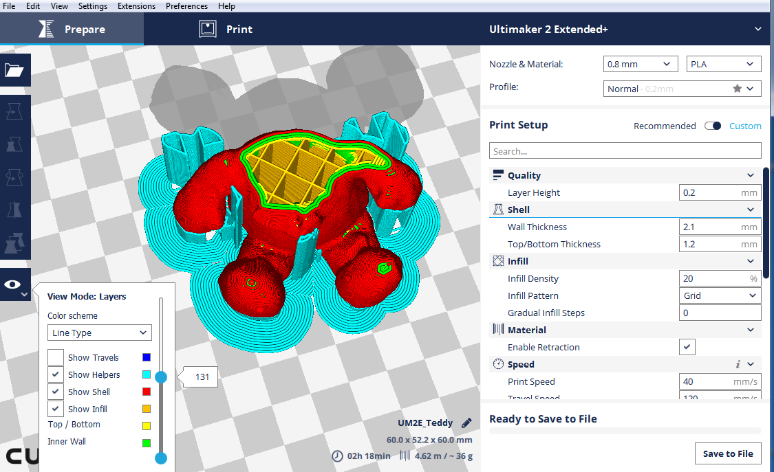
The overhang angle was set to 65 degrees.
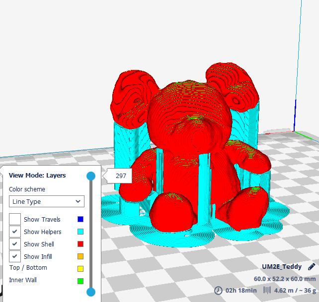
Printing the 3D Scan
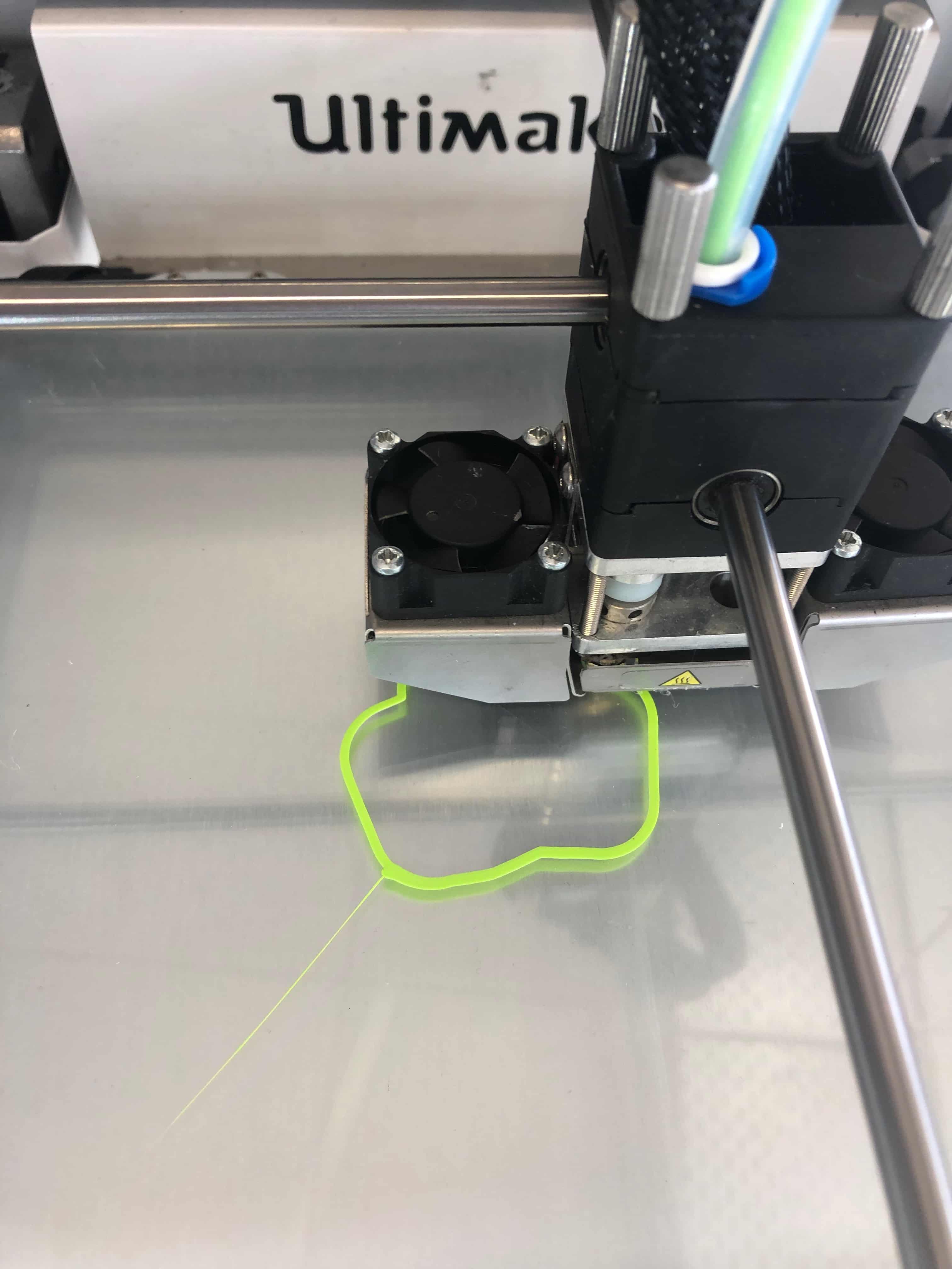
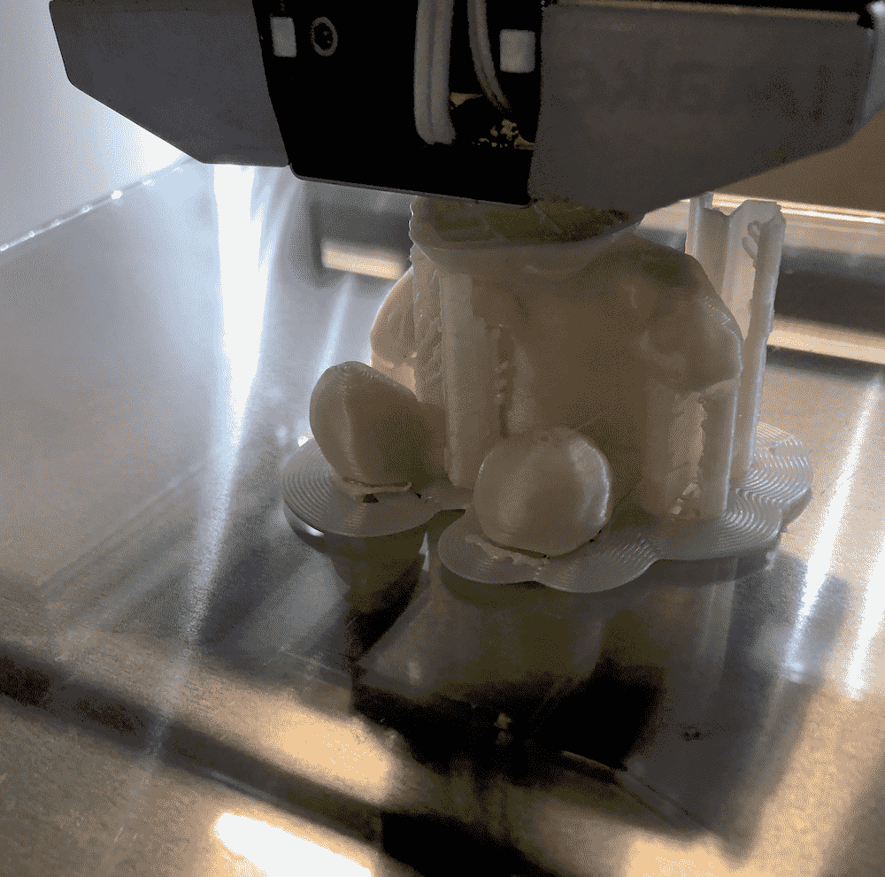
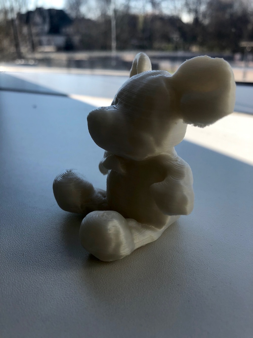
Below you can see the progess of the print. It took about 2 hours to print with the Ultimaker 2+ Extended using a 0.8mm nozzle.
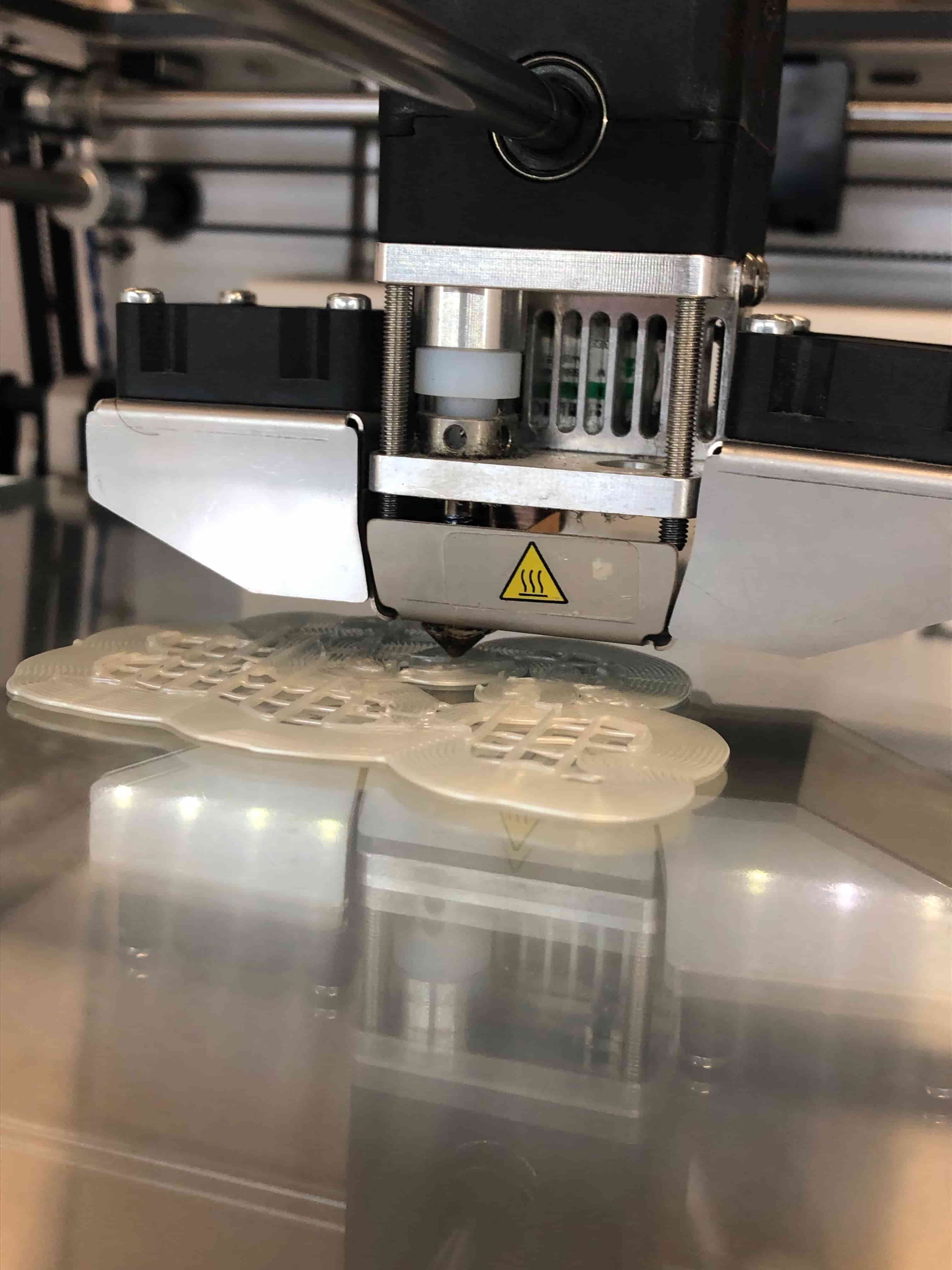
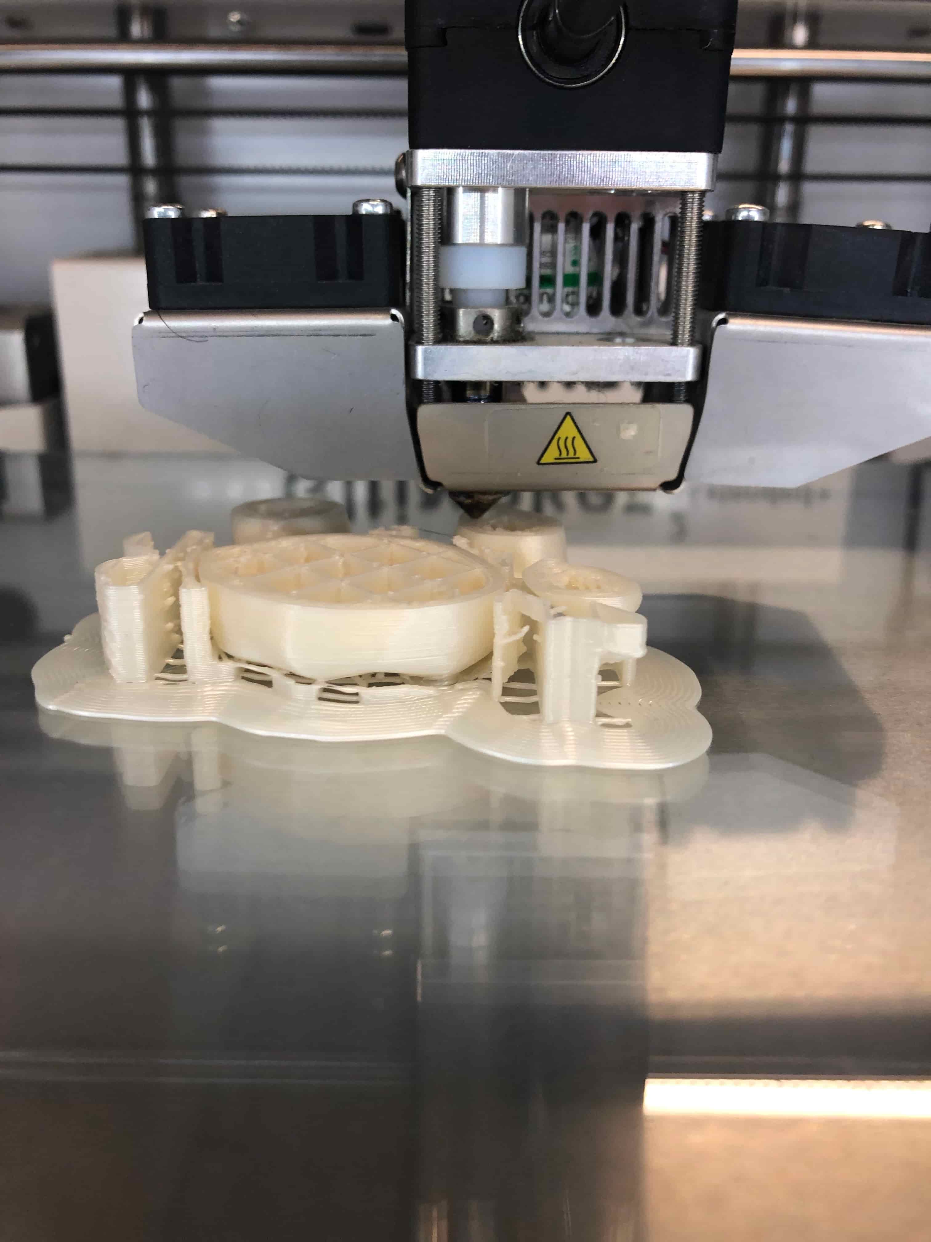
Here you can see how the printer extrudes the filament layer by layer.
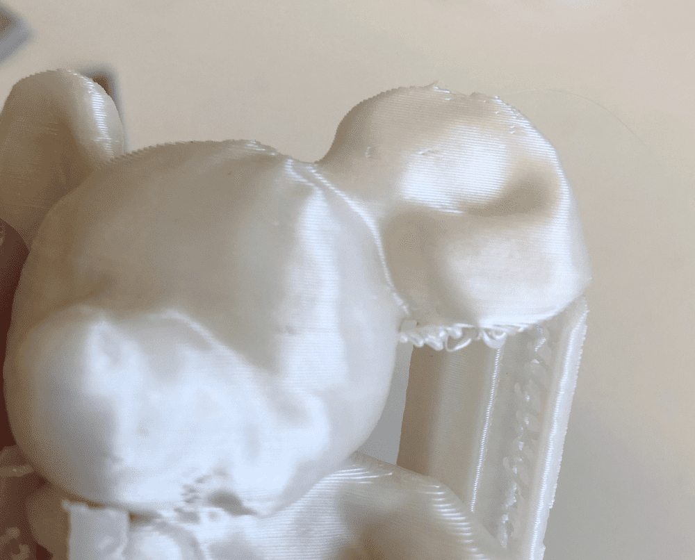
Below you can see thefinished print with support.
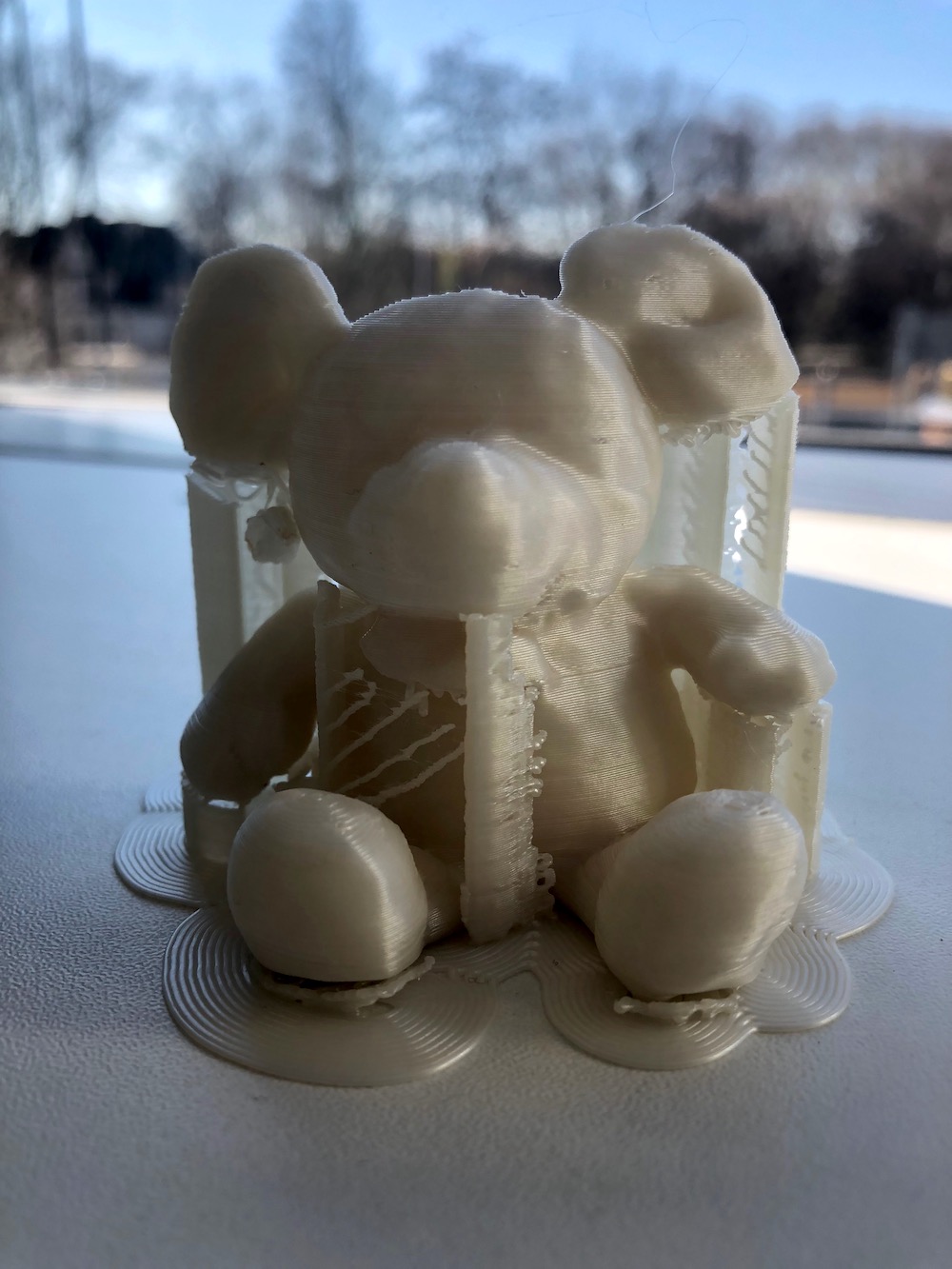
As you can see I should have used a lower overhang angle to avoid, that the filament is printed in the air.
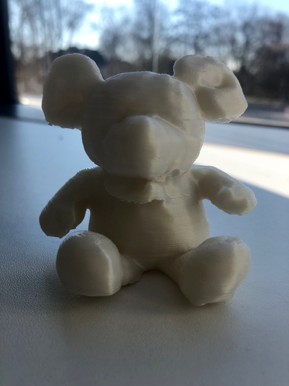
Beside that I think that the print looks amazing and exactly like my stuffed animal!
Download Files
STL-Files
Cube inside CubeRolling ball Toy
Multiple Cubes
3D Scan stuffed animal